
Paper:
Exploiting Mitigation Capabilities of a Variable-Stiffness Joint to Allow Agile Contact with Surfaces
Helio Nonose, Yuki Fukada, and Yasumichi Aiyama

University of Tsukuba
1-1-1 Tennodai, Tsukuba, Ibaraki 305-8573, Japan

The motion patterns typically exhibited by a robot manipulator during a pick-and-place task differ from those by a human. Humans often perform that movement in a manner that resembles a collision while still placing the object safely. This research proposes implementing a fast but rough contact motion by utilizing a series elastic actuator (SEA) on the robot’s joints to introduce compliance. Exploiting the impact mitigation of the SEA allows for high contact velocities while keeping safe values of contact force. The proposed method refrains from controlling the link’s actual position and utilizes contact with the environment to actively attenuate oscillations. The contact forces are limited and attenuated by designing the target position of the motor, joint stiffness, and velocity of the link. Simulation and preliminary results verify the capability of the SEA in mitigating impacts and limiting contact forces. In addition, the influence of each variable over the contact force and settling time is analyzed. Improvements over previous work on a variable-stiffness SEA mechanism based on compressed air are implemented. The proposed method is evaluated through simulation and experiments with a one-link arm. Results demonstrated the feasibility of the method, however, parameter settings need to be investigated.
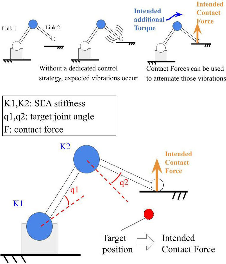
Concept of the proposed method for contact motion
1. Introduction
Pick-and-place tasks are among the most common operations in industrial manufacturing. The approximation velocity is too low to avoid damage due to the impact during contact with the environment.
Contact with the environment techniques is a well-studied topic 1. Although force control is an option, force sensors are sensitive to high impacts. Software-related approaches are limited by the response times of the system components 2,3. Machine learning techniques incur high training costs for training 4,5. Human-like motion research also exists, but most studies have evaluated the path and conclusion of the motion rather than the impact on the environment 6,7,8.
In mechanical approaches, variable-impedance actuators and their variants 9 are often used as collision mitigation techniques.
Among the different types of technologies, this study focuses on series elastic actuators (SEA). Because of its characteristics, only the effective mass (from the SEA joint to the end effector) influences the impact force. Prior studies 10,11 have indicated that safety and productivity can be balanced effectively using a variable-stiffness SEA. These characteristics fulfill the requirements of our proposed method, which is presented in detail in Section 3.
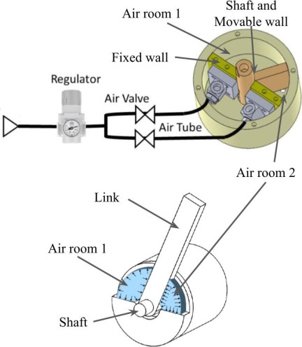
Fig. 1. Antagonist SEA joint mechanism proposed by Aiyama et al. 12.
1.1. Variable-Stiffness Mechanism with Compressed Air
Aiyama et al. proposed a joint mechanism that utilizes compressed air instead of mechanical springs. In this approach, air regulators and valves are positioned outside the joint to keep it light and compact 12 as shown in Fig. 1. The realizable stiffness with this mechanism was \(28.5\times 10^{-3}\) Nm/° at 0.30 MPa. From a practical application perspective, this stiffness would be insufficient to support a robot’s weight and would be subject to high oscillations due to its own motion’s acceleration.
1.2. Research Proposal
As stated earlier, pick-and-place tasks are usually implemented by a robot manipulator using slow placement motion to avoid unwanted contact forces. In contrast, a human operator behaves normally, as shown in Fig. 2.
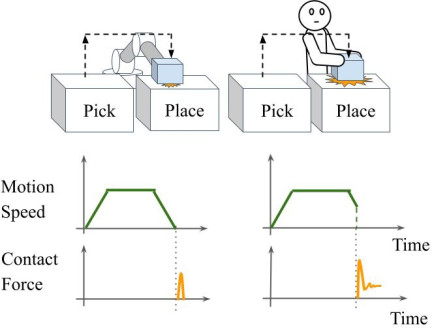
Fig. 2. Comparison between robot’s implementation of pick-and-place task with that of a human.
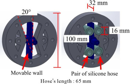
Fig. 3. New design for the SEA.
Considering the joint’s ability to mitigate some of the impacts, we propose mimicking human motion during a place task. This concept exploits the mitigation characteristics to allow contact with a surface with relatively high velocities. Even when speed is not a concern, this concept provides a larger safety margin for positioning by allowing safe contact with the environment.
In this study, we aimed to improve Aiyama et al.’s mechanism and utilize it to mitigate forces when in contact with an environmental surface. The following sections describe the design improvements, prototype construction, proposed contact method simulation, and experiments.
2. Mechanism Improvements
The new design shown in Fig. 3 introduces small silicone hoses as compressed air compartments instead of air rooms. Each hose has a sealed end and a supply entrance for compressed air. In addition, the number of internal chambers is doubled to produce higher restitution forces in the antagonist spring configuration. The inner chamber now has an angle of 20°. This new angle allows for higher torques with smaller compressions compared to the previous design while maintaining a reasonable angle of displacement.
The actuation motor rotates the body of the SEA, and its motion is transmitted through an air spring to the movable wall. The movable wall is connected to a shaft that transmits the torque to the output link.
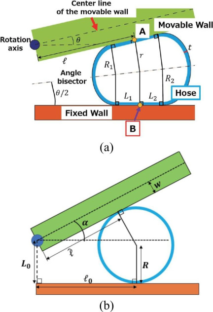
Fig. 4. Geometric model of the cross-section of the hose (a) when the hose is being compressed and (b) when uncompressed.
2.1. Modeling
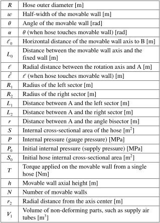
Following the steps of a previous study 12, the restoring force appears owing to a change in the volume of the air inside the silicone hose. In addition, the resultant force is proportional to the new pressure and contact surface of the hose and movable wall. A geometric analysis was used to model these parameters. Fig. 4(a) shows the cross-section of the silicone hose while being compressed by the movable wall, and Fig. 4(b) shows the cross-section of the hose when uncompressed. Point A refers to the point where the movable wall touches the hose when it is uncompressed. Point B is at the center of the contact area and refers to the point where the fixed wall touches the hose when it is uncompressed. Table 1 lists these variables.
Table 1. Parameters of the model.
First, \(r\) and \(\ell\) are obtained through Eqs. \(\eqref{eq:1}\) and \(\eqref{eq:2}\):
\(R_1\) and \(R_2\) can now be computed from Eqs. \(\eqref{eq:3}\) and \(\eqref{eq:4}\):
It is important to note that this model does not include the resistance to deformation of the hose or the material properties of the material (silicone). Thus, the perimeter of the cross-section of the hose length is considered constant. By considering the distance between points A and B, Eqs. \(\eqref{eq:5}\) and \(\eqref{eq:6}\) can be obtained:
With these equations, it is possible to obtain the area of the cross-section of the hose using Eq. \(\eqref{eq:7}\):
The difference in pressure on each side of the movable wall is calculated using Boyle’s law 12. However, it is important to notice that the equilibrium is calculated at an angle \(\theta\) of 20° for this specific mechanism.
The torque \(T\) produced by a single hose can be calculated using Eqs. \(\eqref{eq:9}\) and \(\eqref{eq:10}\).
Finally, considering the influence of both sides acting on the movable wall, we obtain the torque transmitted to the output link using Eq. \(\eqref{eq:11}\). \(T_1\) represents the torque calculated using Eq. \(\eqref{eq:10}\) for the side of the compressed hose, while \(T_2\) represents the torque from the uncompressed hose.
2.2. Joint’s Stiffness Verification Experiment
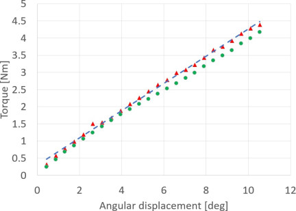
Fig. 5. Experimental curve (red), theoretical curve (green), and the linearized line (blue dashed) of the estimated stiffness at 0.10 MPa considering the total air volume in the supply lines.
As mentioned in Section 2.1, the model does not include the influence of the hose and its material. Thus, the torque values obtained from the theoretical model are related to the volume changes. Measurements without compressed air in the mechanism were taken to take into account the properties of the hose. Fig. 5 shows the curve obtained when the initial pressure on the mechanism was 0.1 MPa.
The theoretical and experimental values were slightly different because of unexpected internal movements of the hose, offsets in the angle measurements, and unwanted play between the internal parts of the mechanism. Nonetheless, the behaviors were somewhat similar, as shown in Fig. 5. The values listed in Table 2 were obtained using a linear approximation of the curves.
Table 2. Relationship between air pressure and observed joint stiffness.
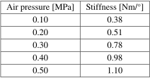
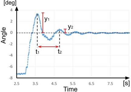
Fig. 6. One of the graphs used to calculate the damping coefficients.
The new design withstood pressures of 0.50 MPa and realized a stiffness of around 1.10 Nm/°. For a direct comparison with the old design, it was possible to increase the realized stiffness by approximately 27 times, at 0.30 MPa.
2.3. Joint’s Damping Coefficient
During the experiments, the mechanism exhibited signs of high-damping behavior. Therefore, we proceeded to identify the corresponding coefficients.
As mentioned in 13, the damping coefficient can be extracted from the experimental values using the graph shown in Fig. 6 and Eq. \(\eqref{eq:12}\).
To obtain the graphs required for estimation, the link was manually displaced to a predetermined angle and released. The angular position of the link was recorded during this process. A weight of 1 kg was added to increase the moment of inertia of the link, as shown in Fig. 7, thus making it easier to observe the oscillations. The experiment was conducted three times at a pressure of 0.1 MPa and an initial displacement angle of 7.5°. The average was taken to obtain the value 0.303 for \(\zeta\).
For the former mechanism, the damping values were not extracted. This value was used to obtain the results shown in Fig. 18 (in Section 5). However, in Section 4, a smaller damping value was used to clarify the oscillations.
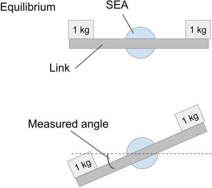
Fig. 7. Experimental setup to estimate the damping coefficient of the mechanism.
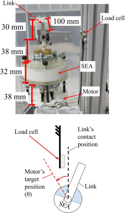
Fig. 8. Setting for the preliminary experiments.
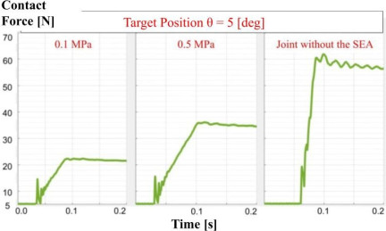
Fig. 9. Comparison of contact forces for different stiffness values.
2.4. Preliminary Experiments of Contact with the Environment
The objective of this preliminary experiment was to verify the behavior of the SEA joint during contact with a surface. The experimental setup is shown in Fig. 8. An aluminum frame with a length of 100 mm (20 mm \(\times\) 20 mm) was used as the link for the setup. At the extreme end of the link, a small part was used to allow contact with the load cell (A&D LCCA21-N200) without touching the environment (e.g., bolts). The link was attached to a connector fabricated using a 3D printer (Formlabs Resin Rigid 10k). This connector also imprinted the shaft and movable wall of the SEA. Long bolts were used to attach the SEA to a plate connected to a motor (Dynamixel PM42-010-S260-R). This configuration was necessary to allow space for the air tubes and the parts used to seal the hoses. The hose had an external diameter of 16 mm and a thickness of 3.25 mm, and it was positioned at a distance of 24.65 mm from the center of the rotation axis. The entire structure weighed 0.892 kg.
Different stiffness values and target position settings were evaluated. Considering the velocity at the tip of the link, the contact velocity was 0.125 m/s. For comparison, the link was fixed to the joint body to represent the case in which the compliance feature was not present.
As shown in Fig. 9, without the SEA, the contact force increases faster and stabilizes at higher values. Theoretically, this increase should be almost instant. The initial peak and slope indicated some flexibility in the system. This can be explained by the fixation of the link to the body of the joint, which allowed some clearance between the connecting parts.
With the SEA, contact force stabilizes at the expected value corresponding to the joint’s stiffness and target position.
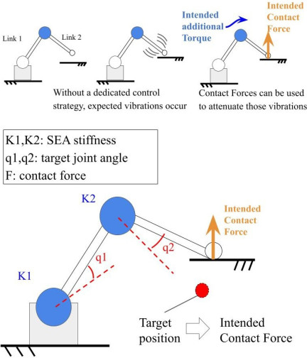
Fig. 10. Concept of the proposed method for contact motion.
3. Proposed Method for Fast Contact Motion
Taking inspiration from human motion, this method exploits the mitigation characteristics of an SEA joint to allow contact with a surface with relatively high velocity. Using this approach, we can contain vibrations due to the elastic characteristics of the SEA by simply pressing the link against the environment. We hypothesized that this could be safely achieved by optimizing the key parameters. Fig. 10 illustrates the proposed concept.
The target joint motor position is set beyond the contact point. Without slowing down, the link hits the surface, and the oscillations caused by bouncing back are attenuated by the ongoing rotation of the motor. When the target motor position is achieved, the expected compliant angular displacement in the SEA is also achieved. This allows the prediction of the contact force against the environment. However, the intended contact force does not include frictional forces.
Modeling contact with the environment is challenging because of multiple variables and the difficulty in estimating losses due to sound and heat. We used MATLAB because of its simplicity in generating contact interaction forces.
Various velocities, target positions, and stiffness values were tested in a preliminary experiment using the prototype. The stiffness of the SEA and resulting torque matched the theoretical values, indicating that this mechanism can be used in the proposed method.
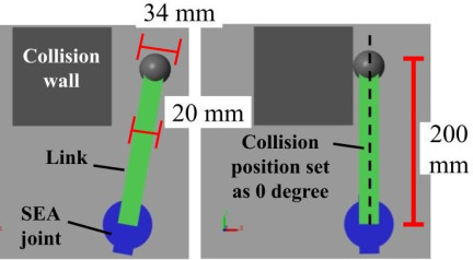
Fig. 11. Simulation setup.
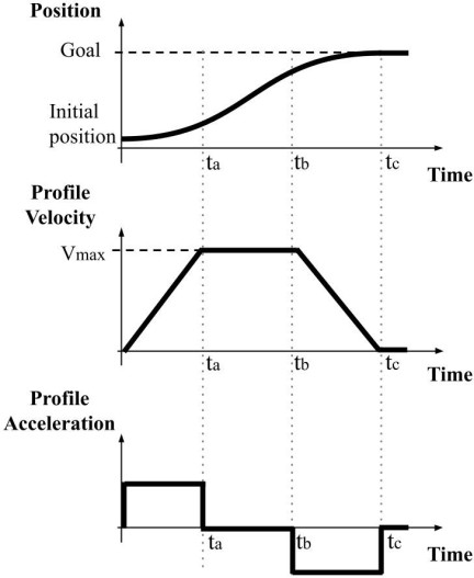
Fig. 12. Control law “velocity profile” implemented in Dynamixel motors. Source: Dynamixel official website.
4. Simulations
Simulations were conducted using MATLAB/Simulink Multibody to observe the effects of different parameters on the contact force and settling time. The setup is shown in Fig. 11. One link (green) 200 mm in length was connected to an SEA joint (blue). The SEA joint was connected to a controlled motor. This setup is different from that presented in Section 2.4. The difference is attributable to a change in the design of the prototype. Although the dimensions and total moments of inertia are different, the properties and behavior of the system should remain the same.
In the simulations, a damping coefficient of 0.004 Nm/(°/s) was used to observe the bounce more clearly. We changed one variable while the others were fixed in a range close to the values expected to be used during the experiments.
4.1. Control Law
The control-law velocity profile shown in Fig. 12 was selected because of the ease of velocity analysis at the moment of contact and ease of implementation with the motor being used.
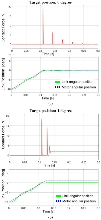
Fig. 13. Comparison when the target position of the motor is set to (a) 0° and (b) 1°. The blue dashed line represents the target position of the motor and the green line represents the link’s actual position.
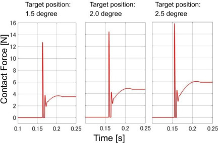
Fig. 14. Comparison of different target positions.
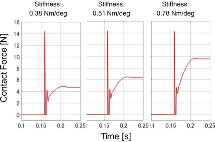
Fig. 15. Comparison of different stiffness values.
4.2. Influence of the Target Motor Position
In the following sections, we illustrate an example case to make it easier to visualize variations. Fig. 13(a) shows the case in which the target position was set to be right over the surface. Values for velocity 0.50 m/s, joint stiffness 0.38 Nm/°, and joint damping coefficient 0.004 Nm/(°/s) were fixed. The link started at a rest angle of 10° from the surface. Some initial oscillations were observed owing to the acceleration imposed by the motor. The motor stopped at 0°; however, the link continued its motion and bounced back until it came to a halt. Fig. 13(b) illustrates the case where the target position was 1°.
Figure 14 shows the behavior of the contact forces at different target positions. Values for velocity 0.50 m/s, joint stiffness 0.38 Nm/°, and joint damping coefficient 0.004 Nm/(°/s) were fixed.
As expected, bouncing was forcibly attenuated as the target position increased. After the oscillations ceased, a straight crescent curve was observed that reflected the compliant displacement of the joint and velocity of the motion. After the target position of the motor was reached, the contact force stabilized at the theoretical value dictated by the joint stiffness and compliant displacement.
4.3. Influence of the Joint Stiffness
Values for velocity 0.50 m/s, target position 2.0°, and joint damping coefficient 0.004 Nm/(°/s) were fixed, and the results for different joint stiffnesses are shown in Fig. 15. The settling times were approximately the same (0.016 s). However, as expected, the final contact force increased. Considering the range studied, it is possible to argue that the joint stiffness should be designed more carefully than the target position to maintain the contact forces under the desired limit.
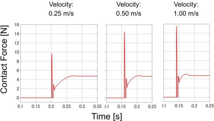
Fig. 16. Comparison of different velocities.
4.4. Influence of the Contact Velocity
The speed limit for the collaborative robots was set to 0.25 m/s 14. Although industrial robots can achieve higher velocities using proper safety safeguards, this study investigated cases similar to collaborative robots.
Higher velocities exhibited high peaks at the first contact, as shown in Fig. 16. However, this parameter’s range showed almost negligible influence over the link’s settling time, all close to 0.05 s. Therefore, the velocity can only be considered when designing the first contact force peak.
4.5. Simulation Results
While the contact without an SEA joint produced a very sharp increase in the contact force, the results with the SEA joint showed a smoother slope. This time interval can be exploited by control techniques that are typically not considered sufficiently fast to respond to the fast characteristics of the contact force.
The effect of each parameter was determined by examining the results. However, the optimum choice of parameters to obtain a smaller contact force and shorter settling time is yet to be determined.
5. Experiments
To verify the simulation results and the proposed method, the prototype shown in Fig. 17 was built. The chosen configuration differed from that used in the previous tests. The new configuration aimed to allow better structural stability and further expansion of multiple links in the future. The motor was changed (Dynamixel XH540-V270-R) to provide a slightly higher power. These changes did not interfere with the research, as the purpose of the previous tests and simulations was only to verify the SEA’s response to collisions. The new configuration weighed 1.12 kg, and its moment of inertia was approximated as a simple link in the simulation environment to obtain the results shown in Fig. 18.
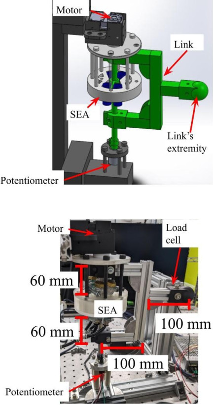
Fig. 17. One-link arm experimental device.
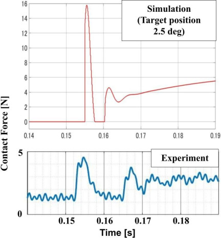
Fig. 18. Comparison between the expected result (from simulation) and the experiment results.
5.1. Conditions and Settings
The parameters chosen for the investigation were a velocity 0.50 m/s, stiffness 0.38 Nm/°, and target position 2.5°. These settings were aimed at observing the behavior of fast contact with low stiffness and a deep target position in the experiment.
5.2. Experimental Results
Figure 18 shows the results obtained from the simulations and the actual data collected from the experiment. Noteworthily, the sensor had an initial bias of 1.5 N that could not be calibrated.
Although the behavior of the curves was similar, the contact force in the experiment was almost one-third of the expected value. The contact force after the transient period was approximately 1.5 N, which corresponded to a compliant displacement of 0.67°, which was not the desired value of 2.5°. A plausible reason for this is the connection stiffness between the link and other unaccounted for damping characteristics. The velocity at which the contact is made may not be set, which can explain the low values of the contact force.
6. Conclusion
The present study improved the design of the proposed compressed-air SEA. The new design still allows the positioning of the instrumentation outside the joint, enabling a compact configuration. However, the supply connection increased the size of the joint in the longitudinal direction. It is also important to note that the proposed contact method is independent of the developed variable-stiffness SEA. If there is no intention to change the stiffness, a standard SEA can be used.
The model and observed data showed similar behaviors. However, this study is limited in that it was not extensive because the limits of the mechanism were not verified. We did not conduct experiments by changing other parameters such as joint stiffness. However, we believe that behavior similar to that shown in Fig. 14 can be obtained.
The proposed method showed the expected impact mitigation properties, and large oscillations were attenuated by actively pressing the link against the environment. This allowed us to demonstrate the possibility of not actively controlling the actual position of the link. However, this study did not consider different moments of inertia, which can have a significant impact.
New developments require further investigation using an arm with more degrees of freedom. Finally, verification is necessary in a complete pick-and-place scenario with stiffness changes to consider unexpected contacts with humans and expected contacts with surfaces.
- [1] M. Suomalainen, Y. Karayiannidis, and V. Kyrki, “A survey of robot manipulation in contact,” Robotics and Autonomous Systems, Vol.156, Article No.104224, 2022. https://doi.org/10.1016/j.robot.2022.104224
- [2] D. Tommasino, G. Cipriani, A. Doria, and G. Rosati, “Effect of end-effector compliance on collisions in robotic teleoperation,” Applied Sciences, Vol.10, Article No.9077, 2020. https://doi.org/10.3390/app10249077
- [3] B. Ugurlu, P. Forni, C. Doppmann, E. Sariyildiz, and J. Morimoto, “Stable control of force, position, and stiffness for robot joints powered via pneumatic muscles,” IEEE Trans. on Industrial Informatics, Vol.15, No.12, pp. 6270-6279, 2019. https://doi.org/10.1109/TII.2019.2916228
- [4] C. C. Beltran-Hernandez, D. Petit, I. G. Ramirez-Alpizar, and K. Harada, “Variable compliance control for robotic peg-in-hole assembly: A deep-reinforcement-learning approach,” Appl. Sci., Vol.10, Article No.6923, 2020. https://doi.org/10.3390/app10196923
- [5] M. Nishiura, A. Hatano, K. Nishii, and Y. Okumatsu, “Development of low-inertia backdrivable arm focusing on learning-based control,” 2022 IEEE/RSJ Int. Conf. on Intelligent Robots and Systems (IROS), pp. 9642-9649, 2022. https://doi.org/10.1109/IROS47612.2022.9981337
- [6] G. Gulletta, W. Erlhagen, and E. Bicho, “Human-like arm motion generation: A review,” Robotics, Vol.9, No.4, Article No.102, 2020. https://doi.org/10.3390/robotics9040102
- [7] E. Costa, E. Silva, M. F. Costa, J. P. Araújo, D. Machado, L. Louro, W. Erlhagen, and E. Bicho, “Towards human-like bimanual movements in anthropomorphic robots: A nonlinear optimization approach,” Applied Mathematics and Information Sciences, Vol.9, pp. 619-629, 2015.
- [8] F. Zacharias, C. Schlette, F. Schmidt, C. Borst, J. Rossmann, and G. Hirzinger, “Making planned paths look more human-like in humanoid robot manipulation planning,” Proc. IEEE Int. Conf. on Robotics and Automation, pp. 1192-1198, 2011. https://doi.org/10.1109/ICRA.2011.5979553
- [9] B. Vanderborght, A. Albu-Schäeffer, A. Bicchi, E. Burdet, D. G. Caldwell, R. Carloni, M. Catalano, O. Eiberger, W. Friedl, G. Ganesh, M. Garabini, M. Grebenstein, G. Grioli, S. Haddadin, H. Höppner, A. Jafari, M. Laffranchi, D. Lefeber, F. Petit, and S. Wolf, “Variable impedance actuators: A review,” Robotics and Autonomous Systems, Vol.61, pp. 1601-1614, 2013. https://doi.org/10.1016/j.robot.2013.06.009
- [10] A. Bicchi and G. Tonietti, “Fast and “soft-arm” tactics [robot arm design],” IEEE Robot. Autom. Mag., Vol.11, No.2, pp. 22-33, 2004. https://doi.org/10.1109/MRA.2004.1310939
- [11] S. Song, X. Zeng, Y. She, J. Wang, and H.-J. Su, “Modeling and control of inherently safe robots with variable stiffness links,” Robotics and Autonomous Systems, Vol.120, Article No.103247, 2019. https://doi.org/10.1016/j.robot.2019.07.017
- [12] Y. Aiyama, K. Tadokoro, and Y. Fujimori, “Variable stiffness mechanism with compressed air for robot SEA joint device,” 49th Int. Symp. on Robotics, 2017.
- [13] A. B. Alhassan , X. Zhang, H. Shen, H. Xu, K. Hamza, and G. Masengo, “Precise motion control of a power line inspection robot using hybrid time delay and state feedback control,” Frontiers in Robotics and AI, Vol.9, Article No.746991, 2022. https://doi.org/10.3389/frobt.2022.746991
- [14] International Organization for Standardization, “Robots and robotic devices – Collaborative robots,” 2016.
This article is published under a Creative Commons Attribution-NoDerivatives 4.0 Internationa License.