
Paper:
Wearable Assistive Robot for Torso Support: Managing Contact Force Distribution with Wearers
Shinichi Masaoka
 , Yuki Funabora†
, and Shinji Doki
, Yuki Funabora†
, and Shinji Doki
Department of Information and Communication Engineering, Nagoya University
Furo-cho, Chikusa-ku, Nagoya, Aichi 464-8603, Japan
†Corresponding author

Wearable assistive robots have been studied widely to reduce the physical burden of tasks such as lifting and caregiving. Most existing systems, however, control only the joint torque. Even though wearable robots transmit actuator forces through direct contact with the body, these systems do not focus on managing the contact force generated at the human–robot interface. Our previous study developed wearable assistive robots capable of measuring and controlling the contact-force distribution. We verified the feasibility of evaluating safety and control performance using a single-joint arm-mounted robot and a multi-joint whole-body robot. However, the influence of force distribution on assist performance was not been sufficiently examined for multi-joint robots under assist conditions. The current study aimed to experimentally verify the effectiveness of using contact-force distribution information in a torso-mounted multi-joint robot (through experiments involving seven participants). The results showed that whereas the actual motor torque tracked the commanded torque under conventional torque-based control, the contact-force distribution experienced by the wearer varied across participants. This finding indicates that for wearable robots with complex joint structures, assessments of wearing states and assist effectiveness require an evaluation of the contact-force distribution in addition to the torque.
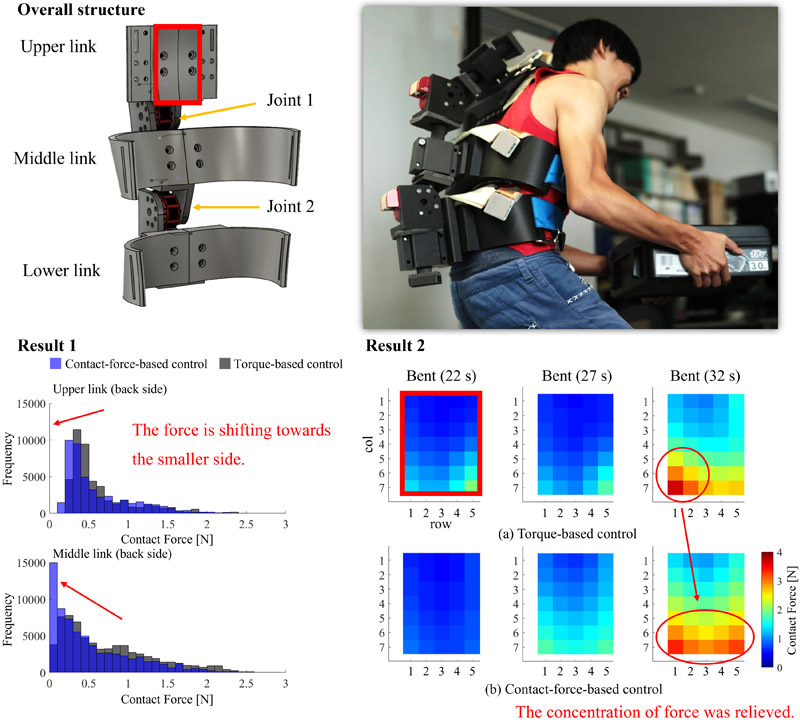
Overall structure and results
1. Introduction
Personnel estimates (for 2025) indicate a shortfall of 377,000 with an expected demand of 2,530,000 and supply of 2,151,000 caregivers (according to the Ministry of Health, Labour and Welfare 1). Retaining caregivers is a critical challenge for long-term care facilities, as many caregivers leave the workforce owing to the significant physical burden associated with the daily tasks. A survey reported that caregivers frequently experience strain across the torso, including the lumbar region, back, and neck 2.
In this context, wearable robots have been studied and developed to provide physical assistance during lifting, which is one of the most demanding tasks in caregiving 3,4,5,6,7,8,9,10,11,12. The HAL waist-type robot by CYBERDYNE 3 supports lifting by detecting electromyographic (EMG) signals that indicate the intended motion of the wearer, whereas the Muscle Suit developed by Innophys 4 uses artificial pneumatic muscles to generate high assistive forces. These devices typically support the wearer torso by actuating the waist joint using motors or artificial muscles, while assuming that the torso from the waist upward can be approximated as a single rigid link. Existing strategies focus primarily on the waist-joint motion support and generally do not consider the motion or structural characteristics of the entire torso.
Replicating the structure of the human torso (which has 33 vertebrae 13) with a wearable robot is difficult, requiring designers to use simplified mechanical models. The discrepancy between the actual motion of the wearer and that of the robot can lead to misalignment, inefficient transmission of the assistive force, and unintended localized pressures acting on the wearer. Therefore, direct measurement and control of the forces applied at the robot–body interface are essential for achieving safe and effective support of the entire torso.
To estimate the force applied to the wearer, the joint torque in existing wearable robots is often determined by either using torque sensors at the robot joints or considering the robot–wearer model 3,4,5,6,7,8,9,10,11. This approach is acceptable when robot joints (such as those in arm or leg exoskeletons) closely correspond to human anatomical joints. However, as torso-mounted robots approximate a complex multi-joint structure, the joint torque does not necessarily correspond to the actual forces experienced by the wearer. As a result, misalignment, localized pressure, and other unsafe conditions cannot be evaluated using the joint torque alone.
To address this issue, we previously proposed wearable robots equipped with surface pressure-distribution sensors for directly measuring the contact forces generated between the robot and human body 14,15,16,17. While pressure distribution has been occasionally used to analyze human body movement 18, its integration into the control of wearable assistive robots is novel. Simulation studies have suggested that measuring and controlling the contact-force distribution could help reduce the localized pressure which cannot be detected through the determination of only the joint torque 14. Experiments using a single-joint arm-mounted robot 15 demonstrated the feasibility of safety evaluation based on contact force, although the control authority was limited by the single joint. Furthermore, experiments with a multi-joint, whole body-mounted robot demonstrated effective tracking control and gravity compensation using contact force-based control 17. However, the force-distribution characteristics during assistive operation in multi-joint torso robots have not yet been thoroughly verified.
The contributions of this study are as follows. First, we qualitatively confirmed that contact force-based control reduces the contact force and alleviates the distribution bias observed under torque-based control during tracking tasks. Second, experiments using torque-based assist control revealed that, although the motor torque accurately follows the command value, the actual force distribution applied to the wearer varies across participants. This indicates that, for wearable robots with complex joint structures, the evaluation of wearing conditions and assistive performance requires an assessment of the contact-force distribution rather than torque information alone. Similar to previous findings on arm-mounted robots, the results suggest that wear characteristics may be inferred from the force-distribution data.
2. Problem Statement
This study aimed to improve the safety of wearable robots and effectively transmit actuator-assisted forces by directly measuring and controlling the contact force acting between the robot and the wearer. As discussed in Section 1, conventional torque-based control does not directly measure the force acting between the wearer and the robot. Wearable assist robots transmit the assist forces through direct contact between the robot and wearer; therefore, accurate measurement of the force acting on the wearer is important for safety. When conventional torque sensors are used, the force acting between the robot and the wearer is estimated from the torque using a geometric model. Experimental implementations of contact force-based control have been attempted in single-joint robots using arms. However, verification that considers attachment misalignment has been insufficient because single-joint robots (such as arms) are inherently less prone to such misalignments 15.
If there is a misalignment between the robot and wearer, and the joint positions are misaligned, model errors occur, making the accurate estimation of the force impossible. The design and development of a robot that mimics human joints are impractical when targeting areas with many joints (such as the torso). Therefore, the design should assume a misalignment between robot and wearer movements for safety considerations. Even if the torque accurately follows the command value at the actuator level, the torque exerted by the actuator may not necessarily match the assist torque applied to the wearer when there is a misalignment. In this situation, even if the actuator exerts the same torque on different wearers, the applied contact force may not be the same depending on the wearer fit and physique. A robot that does not exert the same contact force in response to the given torque command lacks reproducibility of the final output relative to the command value. Even when there is an assist effect, it is difficult to say that it is safely controlled. However, as there is no precedent for incorporating the contact-force distribution into control, no prior studies have clarified this.
To enhance the safety of wearers with varying physiques and to exert an efficient assist force with a reproducible force distribution, we believe that directly measuring and controlling the contact force, is more effective than the conventional method of estimating the contact force using a different sensor. In this study, we built a robot that targets the torso and clarified two aspects. First, we clarified whether contact force-based control, which controls the distribution under tracking conditions, could follow the wearer in the contact-force distribution without bias, relative to conventional torque-based control.
Furthermore, while comparing the performance of both methods under assisted conditions is highly significant, there is still room for improvement in contact force-based control, particularly regarding the determination of appropriate command distributions. Therefore, as a preliminary verification, we conducted experiments using torque-based control with multiple participants under assisted conditions to clarify whether there were differences in the measured contact-force distribution when employing the same torque command value. If different contact-force distributions were observed even with the same torque command value, this would support the hypothesis that in robots with complex structures (such as the torso), simply controlling the torque might not provide sufficient reproducibility of the contact force owing to mounting misalignment or differences in the wearer physique, thus failing to ensure adequate safety.
In these experiments, considering the premise that torque-based controls might contain previously undisclosed risks, safety had to be considered carefully. Therefore, in the second experiment using torque-based control under the assisted condition, setting the actuator output to the lowest possible value (within the range in which the wearer could perceive the assisted force) was deemed desirable, and the contact force-distribution sensor could measure the assisted force from the actuator. Based on these conditions, the actuators were selected to provide the necessary force, heuristically determined by preliminary experiments.
3. Robot Used for Experiments
The wearable robot used in this study was based on our previously proposed torso-assist system, which approximates the human torso using three rigid links 16. Fig. 1 shows the overall computer-aided design model of the robot and its appearance when worn. The robot is designed such that each link conforms to the surface of the wearer torso, thereby improving the fit and enabling more stable contact during motion.
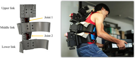
Fig. 1. Overall structure of the wearable torso-mounted assistive robot. Left: Computer-aided design rendering of the three-link configuration. Right: Robot worn by a participant.
3.1. Mechanical Structure
The robot comprises three rigid links, labelled Upper, Middle, and Lower (from top to bottom) connected in series. Each link was fabricated using a three-dimensional printer (Markforged Mark Two) and a carbon–nylon composite material to achieve high rigidity and lightweight construction (Onyx a). The links were 10-mm thick to ensure rigidity. The link geometry was shaped to match the curvature of the wearer torso, ensuring stable attachment during bending or extension.
The links are connected by two actuated joints that allow angular motion corresponding to trunk flexion and extension. The robot was secured to the wearer using Velcro straps around the abdomen to ensure that each link maintained a close contact with the torso. The total mass of the robot is 5 kg, suitable for experiments (with no excessive load on the wearer).
3.2. Actuation
Two HEBI X8-16 smart actuators b were used for the robot joints. Each actuator integrates a direct-current motor, a gearbox, a high-resolution encoder, and a torque sensor. The actuator specifications are listed in Table 1.
Table 1. Specifications of the HEBI X8-16 SmartActuator used in each joint.
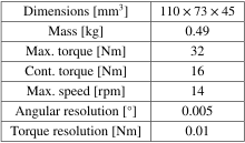
The maximum and continuous torque outputs are 32 Nm and 16 Nm, respectively, sufficient to support the lifting tasks tested in this study. Torque measurements from the actuators were used in the torque-based control experiments, as described in the experiment sections.
3.3. Force Distribution Sensing
To measure the contact-force distribution between the robot and wearer, SR SoftVision [19, c] surface pressure sensors were installed on both the dorsal and ventral sides of the Upper and Middle links. Each sensor provided a spatial resolution of 20 mm and supported a measurement range of up to 200 mmHg. The specifications of SR SoftVision are listed in Table 2, and the sensor arrangement and number of sensor cells are shown in Fig. 2. Because these sensors capture the distributed pressure rather than a single scalar force value, they enable a detailed assessment of how the forces are transmitted across a wide contact area.
Table 2. Specifications of the SR SoftVision surface pressure-distribution sensor.
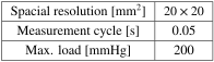
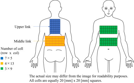
Fig. 2. Arrangement of SR SoftVision surface pressure sensors installed on the dorsal and ventral sides of the Upper and Middle links. The number of sensor cells per region is also indicated (col: column). The image is not to scale (for visual clarity).
A 10-mm urethane-cushioning layer is inserted between the rigid-link surface and the sensor. This padding accommodates individual variations in the torso shape and reduces the discomfort caused by minor misalignments, while still allowing the sensors to detect changes in the contact-force distribution. By combining the conformal link geometry with distributed pressure sensing, the system can capture subtle changes in wearer–robot interactions that are not observable through joint-torque sensing alone. Further details are available in a previous paper 16.
4. Tracking Experiment
The tracking experiment evaluated the ability of the robot to follow the trunk motion of the wearer under torque-based and contact force-based control strategies. The experiment aimed at examining the effect of each of the control methods on the contact force applied to the wearer—when the robot performed pure tracking behavior, without providing active assistance.
4.1. Experimental Setup
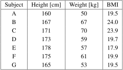
Seven healthy men in their twenties participated in this experiment. The physical characteristics of the participants are listed in Table 3.
Table 3. Physical characteristics of the seven men who participated in the tracking experiment.
All experiments were approved by the Ethics Committee and Engineering Faculty at Nagoya University (Approval No.19-16).
The participants were instructed to sit on a chair and perform a cyclic trunk motion consisting of the following four phases:
-
1)
maintaining an upright posture (reference posture) for 5 s,
-
2)
bending forward to the maximum comfortable angle over 5 s,
-
3)
holding the bent posture for 5 s, and
-
4)
returning to an upright posture over 5 s.
This sequence was repeated three times for each control strategy (a total of 60 s).
To ensure that the measured forces reflected only wearer–robot interaction and not the gravitational effects of the device, the robot was suspended from an overhead support (a suspension mechanism installed in the experimental environment) that compensated for its weight. Thus, the robot exerted no external load on the wearer, other than that generated through physical contact.
4.2. Control Methods
Two different control strategies were implemented and tested in this experiment: torque-based 20 and contact force-based 14. Fig. 3 shows the block diagrams of (a) torque-based and (b) contact force-based control strategies.
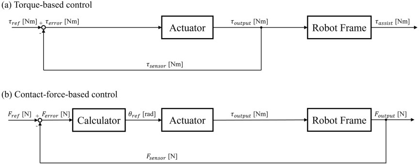
Fig. 3. (a) Torque-based control and (b) contact force-based control.
- (a) Torque-based control:
-
The torque-based control method reduces the deviation (\(\tau_\mathit{error}\)) between the value of the actual torque output (\(\tau_\mathit{sensor}\)) measured by the actuator and the torque command value (\(\tau_\mathit{ref}\)) set by the torque control. The actuator was equipped with proportional-integral control. In tracking control, the command value (\(\tau_\mathit{ref}\)) had to be set to zero. The parameters for torque-based control are shown in Table 4. This approach is representative of conventional wearable robot control systems that rely primarily on torque sensing. The actuator sensor cannot directly measure disturbances in the robot frame (e.g., gravity) and the interaction between the robot and the wearer (e.g., misalignment), so the \(\tau_{output}\) and the net assist torque (\(\tau_\mathit{assist}\)) may not necessarily match.
- (b) Contact force-based control:
-
The contact force-based control method reduces the deviation (\(F_\mathit{error}\)) between the measured value of the actual contact force output matrix by the robot frame (\(F_\mathit{sensor}\)) and the force distribution command matrix (\(F_\mathit{ref}\)) by the position control. The actuator was equipped with proportional control. In the tracking control, \(F_\mathit{ref}\) had to be set to \(O\). The calculator calculates and searches the angle at which the force measured by all sensor cells becomes the command matrix. The control algorithm is used for the model predictive control. For details on the control method, please refer to our previous research 21. The parameters for contact force-based control are shown in Table 5. The force distribution sensor can directly measure the interaction between the wearer and the robot frame as the distribution information (\(F_\mathit{sensor}\)), so the \(F_{output}\) and the net assist force distribution \(F_\mathit{assist}\) are the same value.
The dorsal/ventral elasticity coefficients in the contact force-based control were determined by referring to the literature article 22, and each gain was determined heuristically.
Each parameter was heuristically determined via preliminary experiments conducted by the experimenters. Parameter values are determined so that the wearer found to provide the best tracking performance. During the experiment, the command value (command distribution) is set to zero for both control methods because the robot moves in accordance with the subject’s motion. In other words, the robot is controlled to release the force applied to the subject.
4.3. Experimental Results
Across all seven subjects, both control methods generated contact forces well below the reported pain tolerance limit (dorsal: 294 N, ventral: 125 N) 22, confirming that the robot’s interaction remained safe throughout the experiment. Nonetheless, the two control strategies produced qualitatively different force characteristics, particularly in terms of distribution and temporal variation.
Table 4. Control parameter settings for torque-based control during the tracking experiment.
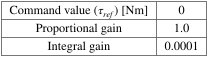
Table 5. Control parameter settings for contact force-based control during the tracking experiment.
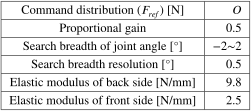
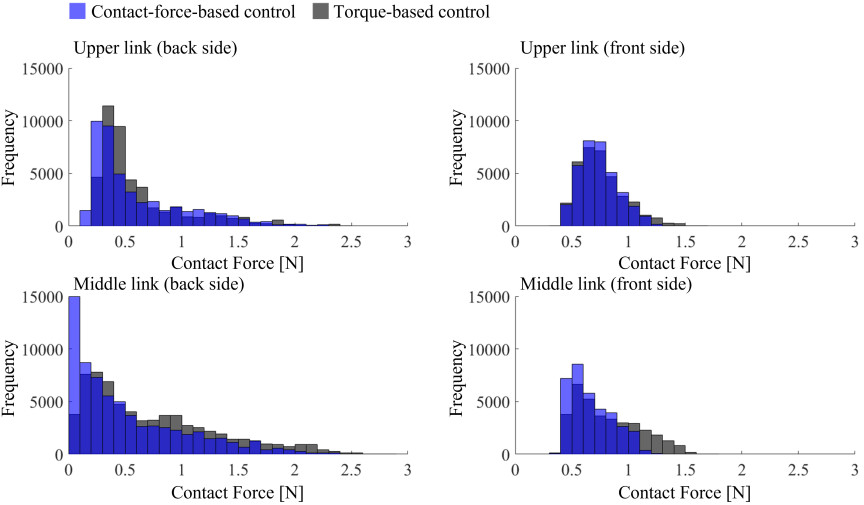
Fig. 4. Contact force frequency (occurrences) for Subject B (the worst case), showing both dorsal and ventral sides under torque-based and contact force-based control.
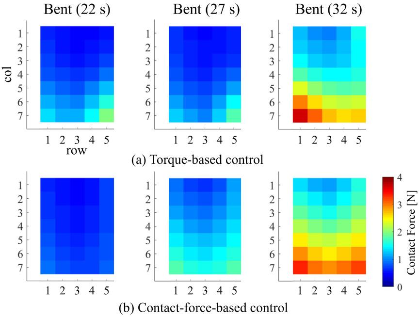
Fig. 5. Comparison of dorsal-side contact-force distributions under torque-based control (a) and contact force-based control (b) in representative postures (col: column).
Figure 4 shows the result of the frequency of contact force in the subject who exhibited the largest overall contact forces (Subject B). Histograms are useful for comparing the trend of the contact forces measured experimentally because they facilitate the observation (at a glance) of all the contact force information of each cell—even though the information in the time direction is reduced. The maximum dorsal-side force recorded under torque-based control was 3.8 N, whereas the ventral-side maximum was 1.8 N. Under contact force-based control, these maxima decreased to 3.5 N and 1.3 N, respectively.
Although the absolute reductions were modest, similar tendencies were observed across multiple participants, indicating consistent suppression of the peak forces. In addition to the maximum contact force, the overall frequency also reveals that contact force-based control causes the robot to operate with smaller contact forces than torque control, because a shift in frequency to the left is observed as an overall trend.
Analysis of the force distribution maps revealed clear differences in spatial patterns. The contact-force distribution of Subject B in typical postures during the exercise (bent, extend, and extended) is shown in Fig. 5. Fig. 5 compares the transition of the force distribution on the dorsal side of the upper link, characteristic of both the control methods. Under torque-based control, high-pressure regions often formed near the edges of the link. Conversely, contact force-based control produced broader distributions, with forces spread across the central regions of the dorsal link. This indicates that the robot and human body were in contact over a larger area, improving conformity to the wearer back and reducing the risk of local pressure buildup.
Comparison across participants revealed the following three recurring patterns:
-
localized dorsal concentration (common under torque control),
-
broad dorsal contact with low ventral load (more common under contact force-based control), and
-
shift of high-pressure regions during movement transitions.
4.4. Discussions
As detailed in Section 4.3, the overall frequency (Fig. 4) reveals that the contact force-based control strategy causes the robot to operate with smaller contact forces than torque control. This trend was not observed for the single-joint arm robot 15; the high degree of control freedom of the multi-joint robot targeted in this study may have contributed to these results. From the results, the measurement of the contact force (contact state) confirmed that the robot could operate without applying any dangerous force to the wearer under follow-up conditions, even for a torso robot with a high degree-of-control freedom. In addition, the proposed method could operate the robot with a smaller contact force under the tracking condition, although the difference was small owing to the smaller output and load.
Figure 5 shows that, even if the magnitude of the contact force measured as a whole in contact force-based control and torque-based control differs only slightly (0.3 N) in comparison to each maximum contact force, the local force was detected as a distribution. It is suggested that the difference in force distribution between the two controls contributes to wearing comfort and assisting force transmission performance.
In summary, contact force (contact state) measurements confirmed that the robot could be operated without exerting a dangerous force on the participant for both control methods—in the tracking control of the torso bending and extending motions. However, when comparing the maximum contact force and frequency, it was found that the contact force-based control method could operate with a slightly smaller contact force. In addition, when comparing the distributions, the contact force-based control was qualitatively confirmed to eliminate the distribution bias observed in the torque-based control. This result is expected to be more pronounced under assistive conditions, when the actuator exerts a greater force.
5. Assist Experiment
The second experiment evaluated the effectiveness of the robot in reducing trunk extensor-muscle activity during a lifting-like motion. In contrast to the tracking experiment, the robot actively applied an assistive torque to the wearer. The purpose of this experiment was to examine whether the assistive torque commanded at the robot joints was properly transmitted to the wearer and to assess the relationship between assist effectiveness and contact-force distribution.
5.1. Experimental Setup
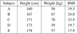
Five of the participants performed a trunk-extension task while holding a 5-kg load. Each participant began from a forward-bent posture and extended the trunk to an upright posture while maintaining the load in front of the body. The physical characteristics of the participants are listed in Table 6.
Table 6. Physical characteristics of the five participants who participated in the assist experiment.
As in the tracking experiment, the target motion in this experiment, too, was bending and extending while being seated on a chair. This target motion is a whole-body coordination task in which the torso, legs, and other body parts work in tandem. To support the actual task, a separate mechanism (leg-mounted robot) was considered necessary—to support the legs by releasing the weight of the robot toward the ground. This experiment was positioned as a basic evaluation of a torso-mounted robot; it targeted the bending and extending motion while the participant wearing the robot was seated on a chair—to verify the support effect by focusing only on the torso movement while the chair did not support the weight of the robot.
The exercises were performed in the following order:
-
1)
maintaining the maximum forward-bending posture,
-
2)
holding the load of 5 kg with a 90° angle between the arm and the body,
-
3)
extending the trunk, over 3 s, to the reference posture while maintaining the angle at 90°,
-
4)
maintaining reference posture while maintaining the angle for 5 s, and
-
5)
releasing the load.
This sequence was repeated three times under two conditions: No-robot condition (No-Exo)—in which the participant performed the task without wearing the robot—and Assistance condition (Exo)—in which the subject wore the robot—which generated assistive torque based on a feedforward model (a total of 8 s for three times). The details of the model are presented in Section 5.2. The order of the conditions was randomized to reduce fatigue-related bias.
Surface EMG was performed on the longissimus muscle to quantify the level of muscle effort during trunk extension. The longest muscle is located in the center of the erector spinae muscle group and is essential for maintaining posture (Fig. 6). The sensor used for the measurement was an ATR-Promotions TSND121/TS-EMG01, a small wireless multifunctional sensor, with a myoelectric amplifier set. The sensor was attached as shown in Fig. 6, and the measurements were performed with a measurement cycle of 1 ms. The EMG waveforms were rectified by applying root mean square (RMS) processing to the measured EMG waveforms over a time span of 100 ms. Considering the differences in muscle mass among participants, RMS data were normalized based on the maximum EMG of the patient for 5 s.
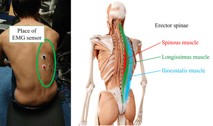
Fig. 6. Placement of the EMG sensor on the longissimus muscle for evaluating muscle activity during the assist experiment.
The average values (\(\overline{\mathrm{RMS}[A_\mathit{Exo}]_n}\), \(\overline{\mathrm{RMS}[A_\mathit{NoExo}]_n}\)) of the RMS-processed normalized EMG over all trials and intervals and the muscle activity reduction rate (\(R_{\mathit{MAR}}\)) owing to robot attachment were calculated for each participant according to Eq. \(\eqref{eq:E1}\).
5.2. Implementation of Assist Control
Torque-based control 20 was used as the robot control method and a simplified kinematic model (Fig. 7) was used to compute the required torque. The output torques of Joints 1 and 2 are represented by \(\tau_1\) and \(\tau_2\), respectively, and they can be obtained using Eq. \(\eqref{eq:E2}\).
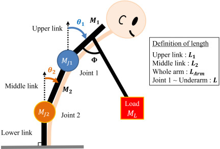
Fig. 7. Model of the multi-joint torso-mounted robot used for determining assistive torque commands.
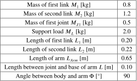
The command torque was determined to assist 2 kg, corresponding to 40\(\%\) of the 5 kg load. To ensure the utmost safety of the participants, based on the preliminary experiments conducted by the experimenter, the value was determined to produce the smallest output while still showing a discernible difference in the results of the experiments. To ensure the smooth application of the assistive force, the commanded torque was gradually ramped up at the onset of extension and similarly ramped down before the end of the motion. This method ensured that any sudden changes in torque would not cause an abrupt force transmission to the wearer. The parameters in Eq. \(\eqref{eq:E2}\) are listed in Table 7.
Table 7. Parameters used for computing commanded joint torques in the assist experiment.
5.3. Experimental Results
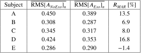
Table 8 summarizes the muscle activity reduction rates of the individual participants. Of the five participants, four exhibited reduced muscle activity under the Exo condition, whereas one exhibited slightly increased activity. Subject D, whose \(R_{\mathit{MAR}}\) was the best, showed a 16.8\(\%\) reduction in muscle activity, whereas Subject E showed no effect of wearing the robot on muscle activity reduction. \(R_{\mathit{MAR}}\) ranged from \(-\)1.4% to 16.8%, with an average reduction of 8.8\(\%\). This confirms that, overall, the robot contributed to reducing muscular effort; however, the degree of assistance differed substantially among the participants.
Table 8. Muscle activity reduction rate for all participants in the assist experiment.
Analysis of the contact force distribution during the task provided further insights into the variability in assist effectiveness. Fig. 8 shows the contact-force distribution on the dorsal side of the second link, indicating its characteristics. The rows represent participants with the most pronounced characteristics, while the columns indicate typical postures (at 0 s: bent; from 1.5 s: extend; at 5 s: extended).
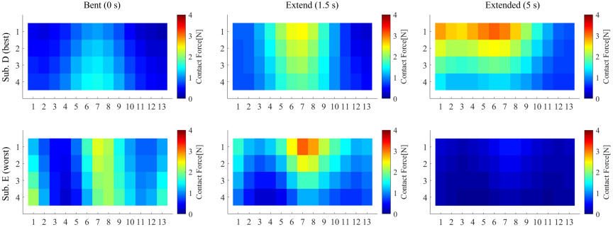
Fig. 8. Representative examples of dorsal-side contact force distribution for Subject (Sub.) E, showing variations across bent, extend, and extended postures.
Subject D (with the highest \(R_{\mathit{MAR}}\), 16.8\(\%\)) tended to maintain wide and stable contact between the robot and torso throughout the extension phase. Here, the dorsal forces were distributed over a broad area and remained nonzero, even in the fully extended posture. This indicated that the robot remained mechanically coupled to the wearer, allowing the commanded torque to be effectively transmitted.
In contrast, around the upper dorsal region, Subject E, (with the lowest \(R_{\mathit{MAR}}\), \(-\)1.4\(\%\)), showed a localized force concentration during trunk extension and near-zero force in the fully extended posture, indicating partial detachment of the robot from the torso. This detachment impaired the transmission of assistive torque, explaining the lack of reduction in muscle activity despite identical control parameters.
Interestingly, despite the differences in assist effectiveness, the recorded actuator torque consistently tracked the commanded torque for all participants. Fig. 9 shows the time series of the output torque during assistance for Subject E. The torque itself tracks the command value well, even though the assist effect is not apparent. This highlights an important limitation of the torque-based evaluation: accurate torque tracking does not guarantee that the wearer receives the intended assistance.
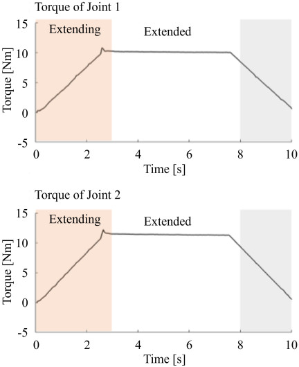
Fig. 9. Time series of measured joint torque for Subject E, demonstrating accurate torque tracking despite reduced assist effectiveness.
5.4. Discussion
The results clearly demonstrate that the mechanical interaction between the robot and wearer, particularly the contact-force distribution, plays a central role in determining the assist effectiveness. Even when using the same assistive torque profile and torque control parameters, the amount of assistance transmitted to the wearer differed considerably among participants owing to variations in the wearer–robot alignment and contact stability.
The negative \(R_{\mathit{MAR}}\) case is particularly illustrative. The force distribution data revealed that the robot–body interface experienced intermittent detachment during the motion. Because the assistive torque is transmitted through physical contact, any floating or slipping between the robot links and the torso disrupts force transmission. Joint torque measurements alone cannot capture this phenomenon because they indicate only whether the actuators are generating the desired torque and not whether that torque is actually delivered to the wearer.
These findings reinforce the limitations of torque-only evaluations for wearable assistive robots, particularly when the robot joint structure approximates a complex human anatomy (such as the torso). They also demonstrate that contact-force distribution serves as a more reliable indicator of assist transmission, providing direct information regarding robot–wearer interaction during dynamic tasks.
Overall, the results imply that effective assist control requires not only accurate torque regulation but also the maintenance of a stable and well-distributed contact state. Therefore, future assistive control strategies may benefit from incorporating force distribution feedback to ensure that the desired torque is effectively transmitted to the body, especially for multi-joint wearable robots with large contact surfaces.
6. Conclusion
This study examined the significance of contact-force distribution in the evaluation and control of a torso-mounted, multi-joint wearable assistive robot. Through tracking and assist experiments involving multiple participants, we demonstrated that measurements of the contact-force distribution provide essential information for understanding and improving human–robot interactions, particularly in systems that interface over broad anatomical regions (such as the torso).
The tracking experiment showed that contact force-based control achieved more uniform and stable force distributions compared with conventional torque-based control, reducing localized pressure peaks and mitigating the effects of structural mismatch between the rigid-link robot and the flexible human torso. These findings indicate that direct force-distribution sensing allows the robot to conform more effectively to individual wearer characteristics and maintain safe and comfortable interactions during dynamic trunk motions.
In the assist experiment, substantial inter-participant variability was observed in the degree of muscle activity reduction, despite consistent torque tracking performance across all participants. The analysis revealed that this variability was strongly influenced by differences in the contact-force distribution; participants with stable, wide-area contact experienced effective assistance, whereas those with partial detachment or concentrated loading received limited benefits. This demonstrates that joint torque alone is insufficient for evaluating assist performance; torque tracking confirms actuator behavior, but not whether the commanded torque is mechanically transmitted to the wearer.
Collectively, the results of both experiments highlight contact-force distribution as a comprehensive indicator of interaction quality, safety, and effectiveness in wearable robots. For torso-mounted systems with complex multi-joint architectures, the force distribution provides critical information that cannot be inferred from joint torque measurements. These insights emphasize the necessity of incorporating contact-force distribution into control strategies, safety evaluations, and individualized fitting procedures.
In future, we plan to focus on developing assistive control algorithms that explicitly regulate or optimize force distribution to ensure safe and effective torque transmission. Establishing desired contact force profiles and adaptive fitting mechanisms will further enhance the usability and performance of wearable assistive robots, contributing to more personalized and reliable support for diverse users.
- [1] Ministry of Health, Labour and Welfare, “Estimates of supply and demand for long-term care personnel towards 2025 (finalized figures),” 2015 (in Japanese).
- [2] Ministry of Health, Labour and Welfare, “The 145th Subcommittee on Interim Long-Term Care Benefits of the Council on Social Security,” 2017 (in Japanese).
- [3] A. Uehara, H. Kawamoto, and Y. Sankai, “Proposal of period modulation control of wearable cyborg HAL trunk-unit for parkinson’s disease/parkinsonism utilizing motor intention and dynamics,” 2023 IEEE/SICE Int. Symposium on System Integration (SII), 2023. https://doi.org/10.1109/SII55687.2023.10039434
- [4] R. Sato, T. Hashimoto, K. Matsumoto, and H. Kobayashi, “Improvement of lower back support exoskeleton: Muscle suit “every”,” 2023 IEEE Int. Conf. on Robotics and Biomimetics (ROBIO), 2023. https://doi.org/10.1109/ROBIO58561.2023.10354763
- [5] S. Toxiri, A. S. Koopman, M. Lazzaroni, J. Ortiz, V. Power, M. P. De Looze, L. O’Sullivan, and D. G. Caldwell, “Rationale, implementation and evaluation of assistive strategies for an active back-support exoskeleton,” Frontiers in Robotics and AI, Vol.5, Article No.53, 2018. https://doi.org/10.3389/frobt.2018.00053
- [6] D. J. Hyun, H. Lim, S. Park, and S. Nam, “Singular wire-driven series elastic actuation with force control for a waist assistive exoskeleton, H-WEXv2,” IEEE/ASME Trans. on Mechatronics, Vol.25, No.2, pp. 1026-1035, 2020. https://doi.org/10.1109/TMECH.2020.2970448
- [7] T. Luger, M. Bär, R. Seibt, P. Rimmele, M. A. Rieger, and B. Steinhilber, “A passive back exoskeleton supporting symmetric and asymmetric lifting in stoop and squat posture reduces trunk and hip extensor muscle activity and adjusts body posture – A laboratory study,” Applied Ergonomics, Vol.97, Article No.103530, 2021. https://doi.org/10.1016/j.apergo.2021.103530
- [8] S. E. Chang, T. Pesek, T. R. Pote, J. Hull, J. Geissinger, A. A. Simon, M. M. Alemi, and A. T. Asbeck, “Design and preliminary evaluation of a flexible exoskeleton to assist with lifting,” Wearable Technologies, Vol.1, Article No.e10, 2020. https://doi.org/10.1017/wtc.2020.10
- [9] O. A. Chittar and S. B. Barve, “Waist-supportive exoskeleton: Systems and materials,” Materials Today: Proc., Vol.57, Part 2, pp. 840-845, 2022. https://doi.org/10.1016/j.matpr.2022.02.455
- [10] T. Luger, M. Bär, R. Seibt, M. A. Rieger, and B. Steinhilber, “Using a back exoskeleton during industrial and functional tasks—Effects on muscle activity, posture, performance, usability, and wearer discomfort in a laboratory trial,” Human Factors, Vol.65, No.1, pp. 5-21, 2023. https://doi.org/10.1177/00187208211007267
- [11] S. Bhardwaj, A. B. Shinde, R. Singh, and V. Vashista, “Manipulating device-to-body forces in passive exosuit: An experimental investigation on the effect of moment arm orientation using passive back-assist exosuit emulator,” Wearable Technologies, Vol.4, Article No.e17, 2023. https://doi.org/10.1017/wtc.2023.12
- [12] S. Nakamae, T. Tanaka, A. Murai, and T. Kusaka, “Torsion as a mechanism for enhancing torso mobility by increasing instantaneous torque transfer ratio,” J. Robot. Mechatron., Vol.37, No.1, pp. 222-230, 2025. https://doi.org/10.20965/jrm.2025.p0222
- [13] P. J. Bazira, “Clinically applied anatomy of the vertebral column,” Surgery (Oxford), Vol.39, No.6, pp. 315-323, 2021. https://doi.org/10.1016/j.mpsur.2021.04.004
- [14] N. Uchiyama, Y. Funabora, S. Doki, and K. Doki, “Control system based on pressure distribution for wearable assist robot on multi-joint body part,” 2016 14th Int. Conf. on Control, Automation, Robotics and Vision (ICARCV), 2016. https://doi.org/10.1109/ICARCV.2016.7838706
- [15] S. Masaoka, Y. Funabora, and S. Doki, “Arm-mounted assistive robot for measuring contact force and evaluating wearer safety,” IEEE Access, Vol.11, pp. 114855-114863, 2023. https://doi.org/10.1109/ACCESS.2023.3324417
- [16] S. Honda, Y. Funabora, S. Doki, and K. Doki, “Markerless measurement system of body surface deformation for structure determination of wearable robot,” 2019 IEEE/SICE Int. Symposium on System Integration (SII), pp. 135-140, 2019. https://doi.org/10.1109/SII.2019.8700351
- [17] S. Masaoka, Y. Funabora, and S. Doki, “Gravity compensation method for whole body-mounted robot with contact force distribution sensor,” IEEE Robotics and Automation Letters, Vol.9, No.9, pp. 7843-7850, 2024. https://doi.org/10.1109/LRA.2024.3433308
- [18] I. Hosoi, T. Matsumoto, S. H. Chang, Q. An, I. Sakuma, and E. Kobayashi, “Development of intraoperative plantar pressure measurement system considering weight bearing axis and center of pressure,” J. Robot. Mechatron., Vol.34, No.6, pp. 1318-1328, 2022. https://doi.org/10.20965/jrm.2022.p1318
- [19] J. Gwak, M. Shino, and A. Hirao, “Early detection of driver drowsiness utilizing machine learning based on physiological signals, behavioral measures, and driving performance,” 2018 21st Int. Conf. on Intelligent Transportation Systems (ITSC), pp. 1794-1800, 2018. https://doi.org/10.1109/ITSC.2018.8569493
- [20] K. Kong, J. Bae, and M. Tomizuka, “Control of rotary series elastic actuator for ideal force-mode actuation in human–robot interaction applications,” IEEE/ASME Trans. on Mechatronics, Vol.14, No.1, pp. 105-118, 2009. https://doi.org/10.1109/TMECH.2008.2004561
- [21] Y. Funabora, S. Doki, and K. Doki, “Contact force distribution predictive control system in wearable robot with tactile sensor,” Trans. of the Society of Instrument and Control Engineers, Vol.58, No.4, pp. 221-228, 2022 (in Japanese). https://doi.org/10.9746/sicetr.58.221
- [22] T. Saito and H. Ikeda, “Measurement of human pain tolerance to mechanical stimulus of human-collaborative robots,” Specific Research Reports of the National Institute of Industrial Safety, Vol.33, pp. 15-23, 2005 (in Japanese).
- [a] Markforged, Inc., “Composites Material Datasheet,” 2023. https://static.markforged.com/downloads/composites-data-sheet.pdf [Accessed May 30, 2026]
- [b] HEBI Robotics, “X-Series Actuator,” 2021. https://docs.hebi.us/resources/datasheets/X-SeriesDatasheet.pdf [Accessed May 30, 2026]
- [c] Tokai Rubber Industries, Ltd., “TRI releases wireless version of ‘SR Soft Vision,’” 2014. https://www.sumitomoriko.co.jp/pressrelease/2013/n51910098.pdf [Accessed May 30, 2026]
This article is published under a Creative Commons Attribution-NoDerivatives 4.0 Internationa License.