
Paper:
Funabot-Grab: Tactile Internet Device Capable of Transmitting Human-to-Human Contact Locations
Shinichi Masaoka
 , Yuki Funabora†
, and Shinji Doki
, Yuki Funabora†
, and Shinji Doki
Department of Information and Communication Engineering, Nagoya University
Furo-cho, Chikusa-ku, Nagoya, Aichi 464-8603, Japan
†Corresponding author

With the development of the internet and the availability of sufficient bandwidth, the performance of haptic devices is considered important because device specifications directly determine the comfort of wearing and the tactile sensations that can be transmitted. The Funabot-Grab is a haptic device that evokes a grabbed tactile sensation. Funabot-Grab can exert a tightening force by controlling the air pressure applied to the artificial muscles. There are seven artificial muscles on the fabric, and the tightening force of each artificial muscle is controlled independently. In a previous study, we used a model arm to incorporate Funabot-Grab into a tactile transmission system with the aim of using it as a tactile internet device. We conducted a preliminary experiment with three subjects as a precursor to the full-scale experiment. It was found that it is possible to transmit the static contact force and its position, even to the subjects. However, it became clear that further improvements to the device are needed for it to be worn optimally on every human body, considering the large degree of individual variation, and to evoke a smoother, continuous tactile sensation.
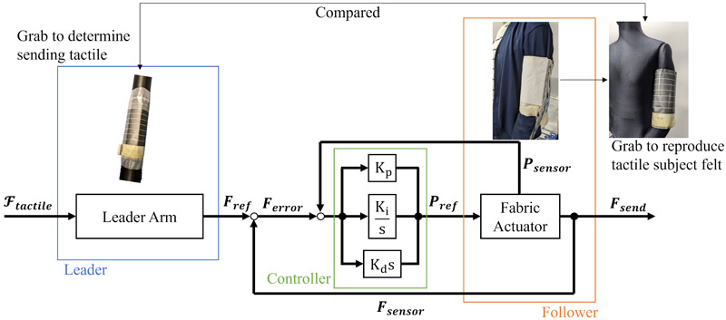
System architecture for tactile internet
1. Introduction
Tactile Internet uses haptic devices to transmit tactile sensations 1,2. With the development of the internet and the availability of sufficient bandwidth, the performance of haptic devices is considered important because device specifications directly determine the comfort of wearing and the tactile sensations that can be transmitted. Various haptic devices using pressure 3,4,5,6,7, vibration 8,9,10, etc. have been investigated and developed. However, conventional rigid exoskeletons are heavy and uncomfortable. Therefore, research on haptic devices that use soft robots is being actively conducted 11,12,13,14,15,16,17,18,19,20.
Funabot is a soft actuator device 21,22,23. The Funabot consists of a base fabric and McKibben-type pneumatic artificial muscles (EM20, s-muscle Co., Ltd., Japan) fixed to the base fabric. It is flexible and freely deformable and can be used as a haptic device. By specializing in Funabot for Grabbed tactile, we developed Funabot-Grab 24, which can control the distribution with force distribution sensors. The Funabot-Grab can independently control the tightening force around the arm in the longitudinal direction, with seven channels. The width of each channel is 2.2 cm. Previous studies have shown that it is possible to achieve a tightening force of 7.9 N for each channel by using a model arm and that the error from the command value is kept to within 0.21 N. On the other hand, there was room for improvement in the response performance, and no experiments were conducted with subjects wearing the device.
This study investigates the feasibility of a tactile internet system through experiments involving human subjects. As a preliminary step toward a full-scale experiment with human subjects, we conducted a tactile internet experiment with three subjects involved in the research.
As a result of the experiment, the subjects were able to reproduce the peaks at the locations where they were grabbed within an error of one channel (2.2 cm). In addition, all the subjects were able to perceive the movement of the locations where they were grabbed.
However, several issues remain to be resolved. Unlike the models used in a previous study 24, the actual arm is difficult to wear the device ideally because the shape of a subjects’ arm varies from person to person, with differences in hardness and length.
In the future, we will consider a mechanism that allows all the subjects to wear the device under the same conditions, and we will increase the channel density to smoothen out continuous locational changes.
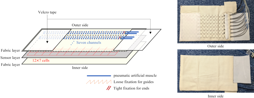
Fig. 1. Design overview and appearance of actual device.
2. Problem Statement
Of the two remaining issues from the previous study 24, namely, room for improvement in response performance and experiments conducted with subjects wearing the device, this study aims to investigate the feasibility of tactile internet via experiments with human subjects. The feasibility of tactile internet with this device was verified by transmitting the grabbed tactile to multiple subjects who had no prior experience wearing the device and by assessing how accurately the subjects perceived the location and size of the transmitted tactile sensation. We also verified whether the force-tracking performance achieved in a previous study 24 when the device was attached to a mannequin could be similarly reproduced when the device was attached to a human. The verification methods and their validity are discussed in Section 4.
The following will not be considered in the experiments, based on the position taken in this study. First, the following experiments were conducted as a preliminary verification before employing the device in a specific application; therefore, transmission delays were not considered. Second, mechanical improvements were made to facilitate the attachment and detachment of the device for multiple subjects; however, no changes were made to the control performance compared to the previous version 24. The details of the device configuration are described in the next section.
3. Device
The operating principle and control method are the same as those in previous versions 24, but the design has been changed to make it easier to attach and detach for use in experiments with human subjects. Fig. 1 shows the design overview and appearance of the actual device. The \(12 \times 7\) cell force distribution sensor was covered with cloth, and artificial muscles were sewn onto the inner (the face that comes into contact with the sensor) of the outer side cloth. There are seven channels of artificial muscles every 2.2 cm, and the tightening force around the arm can be controlled independently in the direction of the upper arm lengthwise. The outer Velcro tape made it easy to wrap around the arm and attach to it. A numerical version of the SR sensor (Sumitomo Riko Company Limited a) was used as the force distribution sensor. The specifications of the sensors are listed in Table 1. For further details, please refer to the previous paper 24.
Figure 2 shows the appearance of wearing. The artificial muscles are sewn on the inside; therefore, the participants could not see them moving during the experiment.
Table 1. Force distribution sensor specifications.
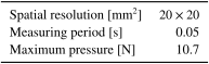
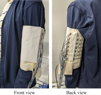
Fig. 2. Appearance of wearing Funabot-Grab.
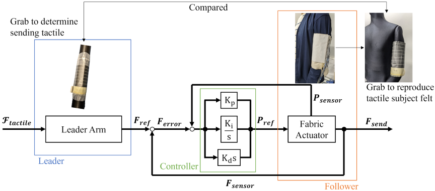
Fig. 3. System architecture used in experiment.
4. Experiment
The experiment was conducted to confirm whether Funabot-Grab could transmit the grabbed tactile between the experimenter and the subject, and whether the subject could perceive it.
The experiment involved the transmission of both static and dynamic tactile sensations. Using the two-point discrimination capacity as a criterion, the experiment examined whether the difference in the peak force applied by the subject to the mannequin sensor compared with the force read by the reader was small or significantly larger than the two-point discrimination capability of the upper arm (20 mm 25). The spatial control resolution of the device used in the experiments was based on the measurement resolution of the sensor. Because the sensor resolution is 2.2 cm wide per channel, if the peak error is within one channel, it means that the tactile position can be recognized within the range of two-point discrimination ability in humans, relative to the control resolution of the device. For dynamic tactile transmission, a questionnaire was administered to determine whether the subject felt the sensation continuously. The tracking performance of the tactile sensation of the device provided to the subject in relation to the tactile input from the reader was evaluated based on whether the output of the device tracked the input to the reader within a tracking error of 0.21 N, achieved in a previous study.
The Ethics Committee of the Graduate School of Engineering, Nagoya University, approved the experiments (Approval No.22-31).
4.1. System Architecture
Figure 3 shows an overview of the system used in the experiment. The reader-follower system enables the transmission of tactile sensations. On the leader side, the sensor is wrapped around the arm model to generate a command distribution. On the follower side, the subject wore the Funabot-Grab, which consisted of an actuator and force distribution sensor. On the follower side, there was a mannequin with a force distribution sensor wrapped around the arm. By using the mannequin as the subject, the location and strength of the sensation felt by the subject can be reproduced on the mannequin’s sensors, allowing for quantitative evaluation of the tactile transmission performance. \({\symbfcal{F}}_{\textbf{\textit{tactile}}}\) represents the tactile sensation that the experimenter intends to transmit, and \({\symbfcal{F}}_{\textbf{\textit{tactile}}}\) is measured as \({\boldsymbol{F}}_{\textbf{\textit{ref}}}\). \({\boldsymbol{F}}_{\textbf{\textit{send}}}\) and \({\boldsymbol{F}}_{\textbf{\textit{sensor}}}\) are the force transmitted by the Funabot-Grab and the measured value of \({\boldsymbol{F}}_{\textbf{\textit{send}}}\), respectively. \({\boldsymbol{F}}_{\textbf{\textit{error}}}\) is the deviation between \({\boldsymbol{F}}_{\textbf{\textit{ref}}}\) and \({\boldsymbol{F}}_{\textbf{\textit{sensor}}}\). Applied air pressure to the artificial muscles was controlled using a PID controller. \(K_p\), \(K_i\), and \(K_d\) are the gain parameters. \({\boldsymbol{P}}_{\textbf{\textit{ref}}}\) is the air pressure command sent to the electro-pneumatic regulator. The regulator can measure and feedback the air pressure as \({\boldsymbol{P}}_{\textbf{\textit{sensor}}}\) is applied to each artificial muscle.
\(\symbfcal{F}\) is a two-dimensional vector and \(\boldsymbol{F}\) is a one-dimensional vector. According to the design of the artificial muscle orientation of the Funabot-Grab, the degree of control freedom is limited by the tightening force in the circumferential direction of the arm. Therefore, \(\symbfcal{F}\) degenerates in the longitudinal direction of the arm, and the tightening forces in each position (channel of the artificial muscle) are controlled independently. Each element of \({\boldsymbol{F}}_{\textbf{\textit{ref}}}\), the vector, is calculated by summing the contact forces of the corresponding channels in \(\symbfcal{F}\) (Fig. 4).
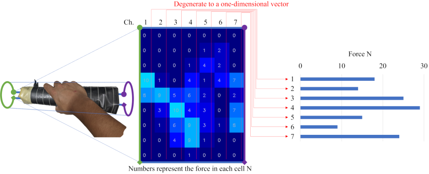
Fig. 4. Tactile force measurement as 2-D \(\symbfcal{F}\) by a sensor and how to degenerate to 1-D \(\boldsymbol{F}\). Each element of \({\boldsymbol{F}}_{\textbf{\textit{ref}}}\) vector is calculated by summing the contact forces of corresponding channel in \(\symbfcal{F}\).
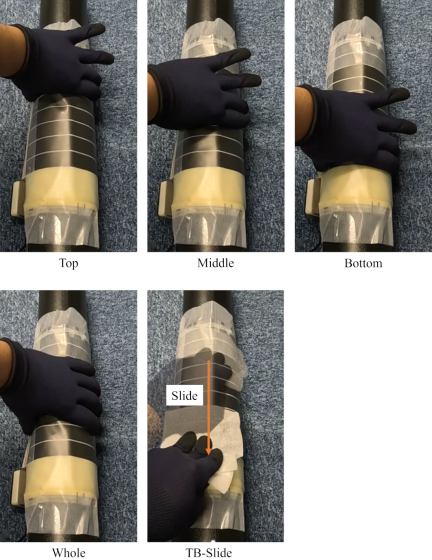
Fig. 5. Five command patterns: Top (shoulder side), Middle, Bottom (elbow side), Whole, and Slide from Top to Bottom (TB-Slide).
4.2. Experimental Condition
Three individuals participated in the study. The participants faced the mannequin while wearing the device. The device and leader sides were positioned so that they could not be seen by the subjects. First, air pressure was applied once to the artificial shoulder-side and elbow-side muscles to obtain an understanding of the positions of the two ends of the device. The experimenter touched the sensor used to generate the command distribution using five different patterns. The subjects were instructed to imagine that the mannequin was themselves and to reproduce the tactile sensation in the same place with the same strength when the test subjects felt a tactile sensation from the device. The five command patterns (Fig. 5) are Top (shoulder side), Middle, Bottom (elbow side), Whole, and Slide from Top to Bottom (TB-Slide). Each subject was given a label once in random order. The feedback gain is heuristically determined. The control and measurement cycles were of 50 ms duration.
As human body shapes vary, it is difficult to define the same attachment position for each subject. In this experiment, the device was attached to the subjects such that the sensor position of the mannequin and the mounting position of the subject were approximately the same. To mitigate minor discrepancies, the relative deviations were reduced by first having the subjects recognize the top and bottom edges of their own device and then instructing them to apply force such that the device and sensor positions were aligned when reproducing the force they felt on the mannequin. Furthermore, because the contact force is managed based on the difference from the initial mounting state, we believe that the influence of initial mounting conditions was minimal.
4.3. Results and Discussion
Throughout the experiment, all the patterns were tried at once in random order but are presented separately in the results and discussion as the static patterns (Top, Middle, Bottom, and Whole) and TB-Slide.
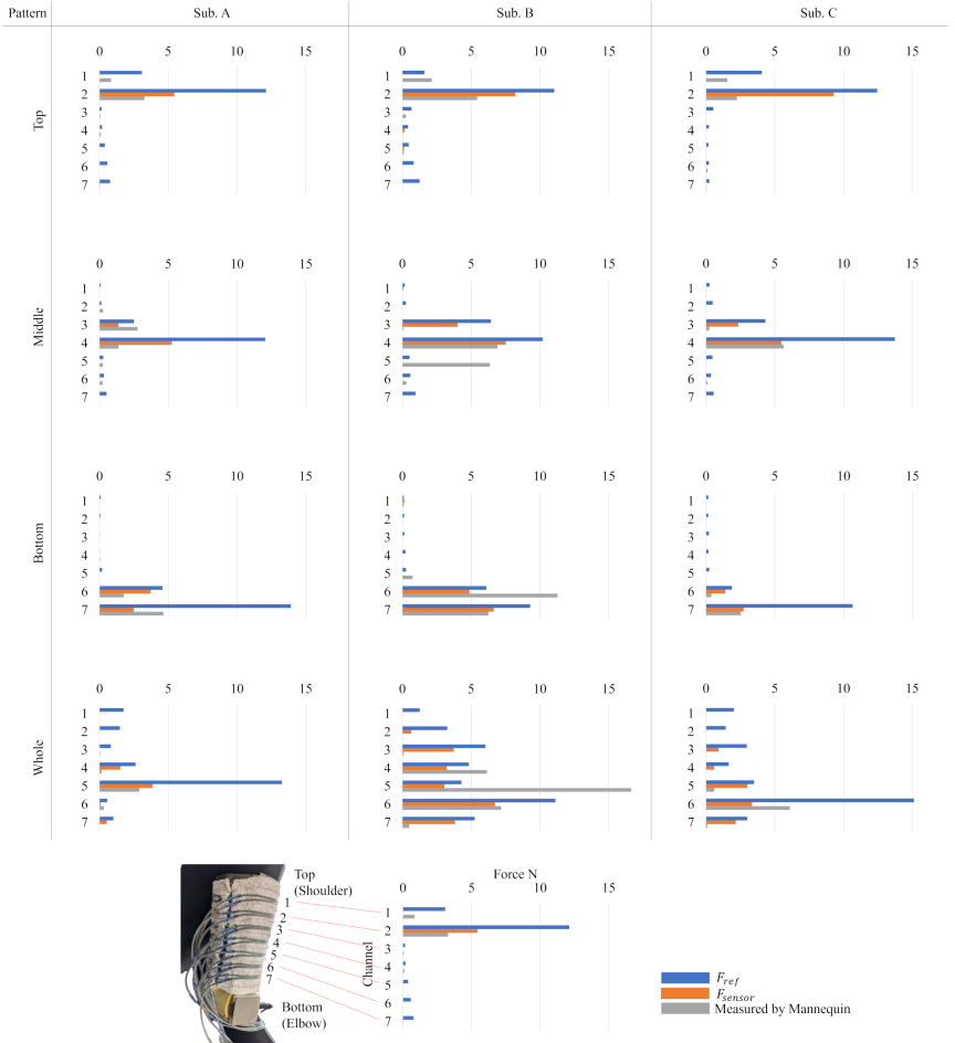
Fig. 6. Experimental results of static pattern.
4.3.1. Static Pattern
Figure 6 shows the results of the Top, Middle, Bottom, and Whole static patterns. The \(x\)-axis represents the tightening force, and the \(y\)-axis represents the channel (1: Top, 7: Bottom) of each graph. The top, middle, and bottom rows show the results for Subject A, Subject B, and Subject C, respectively. Each column shows the results for the Top, Middle, Bottom, and Whole patterns from left to right. The labels in the three colors indicate the power of the sender \({\boldsymbol{F}}_{\textbf{\textit{ref}}}\) (blue), the power exerted by the Funabot-Grab \({\boldsymbol{F}}_{\textbf{\textit{sensor}}}\) (orange), and the subject’s impression as measured by the mannequin (gray).
In explaining the experimental conditions, it was stated that the contact force was managed by the difference from the initial mounting state; however, a negative value meant that the sensors floated to the initial condition. Because floating is irrelevant to the verification of tactile transmission, it was rounded to 0 in the results and discussion.
First, focusing on blue and orange, it is clear that in many cases, the force applied by the device on the follower side cannot track the command value.
The mean absolute error (standard deviation) of orange relative to blue for each channel was 1.8 N (3.0 N) for Subject A, 1.2 N (1.1 N) for Subject B, and 1.8 N (2.8 N) for Subject C, all of which were larger errors than 0.21 N observed in a previous study.
On the other hand, the mean absolute error (standard deviation) of gray relative to orange for each subject was 0.59 N (0.93 N) for Subject A, 1.7 N (3.0 N) for Subject B, and 0.75 N (1.5 N) for Subject C. Gray, representing the subjects’ perceptions, reproduced the actual force applied to the subjects (orange) with an average error of less than 1 N, except for Subject B.
For position, the orange and gray peaks were consistent for the Top, Middle, Bottom, and Whole, except for Subject B’s Middle and Whole, but the error was only one channel (2.2 cm) off.
Excluding Middle and Whole, for which the peak force has shifted error, the mean absolute error (standard deviation) of orange relative to blue for each channel in the Subject B was 0.89 N (0.89 N), and the mean absolute error (standard deviation) of gray relative to orange was 0.93 N (1.7 N). Therefore, the tracking performance of the device still had an error greater than 0.21 N, but without considering the position error, the force reproduction relative to the force actually applied to Subject B was comparable to that of other subjects.
On the other hand, focusing on the Whole, the distribution of gray tended to be narrower than that of orange. In other words, the subjects perceived a tactile sensation over a wider area than when the force was applied.
These results led to the following hypotheses. First, regarding the transmission of position, the perception of the force position remained within the initial target peak error of 2 cm, indicating that the device performed as expected within its capabilities. For example, although Subject B accurately perceived the position at the Top and Bottom, the subject misperceived the position or perceived a narrower range in the Middle and Whole. This suggests that the fabric on the device surface or the subject’s clothing may have acted as a filter, thus reducing the stimulus range.
Regarding force transmission, the force-tracking performance was inferior to those reported in previous studies. Furthermore, in many cases, the blue-orange error was larger than the orange-gray error, indicating that the device’s control performance was inferior to the human perceptual resolution. While it is not essential to consider the magnitude of the orange-gray error in the three subjects in this study because it is related to individual perceptual ability and fine motor skills, the fact that the blue-orange error was greater than the orange-gray error is sufficient to clearly support the conclusion that the force-tracking performance of the device is insufficient.
The failure of the force exerted by the device to track the commanded value may be due to the instability of the attachment of the device to the arm. Unlike the plastic arm model used in a previous study 24, the surface shape of the human body is complex and soft. If there is looseness in the initial attachment, a tightening force cannot be fully exerted. Therefore, it was assumed that the command value was excessively large and could not be tracked. The fact that orange is smaller than blue in Fig. 6 supports this hypothesis.
If the aforementioned challenges can be overcome and the device can fundamentally exert greater force, it is expected that subjects will be able to perceive the tactile sensations more clearly and that the positional transmission performance will improve, at least for relatively large forces.
The next challenge is to consider how to design a mounting mechanism that ensures stable attachment without degrading the force-tracking performance, even when worn by a human, and then proceed with considerations regarding control, such as gain design.
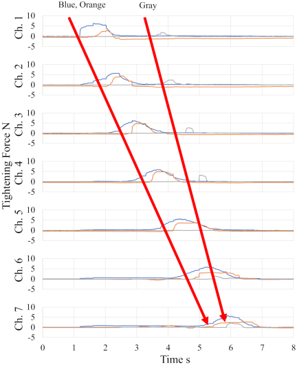
Fig. 7. Experimental results of TB-Slide pattern of Subject A.
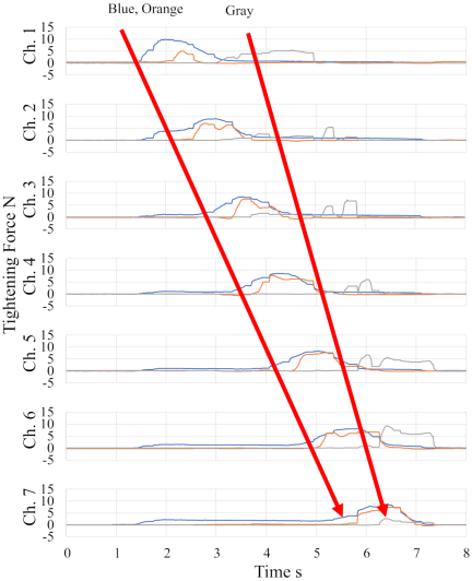
Fig. 8. Experimental results of TB-Slide pattern of Subject B.
4.3.2. TB-Slide Pattern
The results for Subjects A and B are discussed in this paper because Subject C did not show any appreciable force on the sensor, although a tactile sensation was felt. Figs. 7 and 8 show the results of the TB-Slide patterns of Subjects A and B, respectively. The \(x\)-axis represents time [s], and the \(y\)-axis represents tightening force [N]. Each row shows the results for each channel (Ch. 1: top, Ch. 7: bottom). The color legend is the same as in Fig. 6.
For both subjects, the latency for orange was within approximately 1 s of that for blue, indicating that the tactile sensation was transmitted with the same level of latency as that in a previous study 24. This delay in response can be attributed to the physical characteristics of the pneumatic artificial muscles.
In the TB-Slide pattern, the force moves from the shoulder to the elbow over approximately 4 s (blue and orange). On the other hand, the subject’s perceptions (gray) had a delay of approximately 2 s at Channel 1, the starting point of the movement, while at Channel 7, the end point of the movement, the timing was consistent with that of the orange, without delay. The delay at the starting point is the time taken to perceive the tactile sensation and reproduce the force felt on the mannequin. The fact that the timing is in sync at the endpoint of the movement is the result of the subject perceiving the continuous movement of the location where the force is being applied and its speed, and trying to catch up. This shows that it is possible to translate the force movement using this device. However, according to the impressions of the subjects, all three answered that they were able to recognize that the location where the force was being applied was moving but that it was discontinuous. This is most likely due to the channel width of 2.2 cm, which is close to the 2 cm two-point discrimination ability of the upper arm.
From the above, it was suggested that it is possible to present continuous force movement using this device; however, it was also clarified that the channel density of the artificial muscle needs to be increased to make the transmission feel smooth.
5. Conclusion
The tactile internet is a trend in the haptic field. Previous research has shown that the Funabot-Grab can transmit grabbed tactile signals. We conducted a preliminary experiment with the subjects involved prior to the full-scale experiment.
As a result of the experiment, the subjects were able to reproduce the peaks at the locations where they were grabbed within an error of one channel (2.2 cm). In addition, all the subjects were able to perceive the movement of the locations where they were grabbed.
However, owing to the instability of the device attachment to the arm, it was not possible to achieve the tactile reproduction performance shown in a previous study. However, it was suggested that coarse channel spacing relative to the arm’s two-point discrimination threshold likely caused the discontinuous sensation.
In the future, we will consider a mechanism that allows all the subjects to wear the device under the same conditions, and we will increase the channel density to smooth continuous positional changes.
Furthermore, while various studies are being conducted on pressure distribution sensors 26,27, the availability of sensors with higher spatial resolution at lower prices will certainly open new avenues for consideration.
If these challenges are overcome and the control performance of the device improves, further considerations can be made regarding their applications. For example, it can be used to transmit stimuli for remote rehabilitation, where real-time performance is not a priority. However, for purposes where real-time performance is important, such as motion instruction, further consideration of the response performance, which was excluded from the current challenges considered, will be necessary.
Acknowledgments
This work was supported by the JST Japan Primary Research Support Program (JPMJFR216T) and by the Young Scientists Initiative Research Unit Frontier of Nagoya University.
- [1] N. Promwongsa et al., “A comprehensive survey of the tactile internet: State-of-the-art and research directions,” IEEE Communications Surveys & Tutorials, Vol.23, No.1, pp. 472-523, 2021. https://doi.org/10.1109/COMST.2020.3025995
- [2] S. K. Sharma, I. Woungang, A. Anpalagan, and S. Chatzinotas, “Toward tactile internet in beyond 5G era: Recent advances, current issues, and future directions,” IEEE Access, Vol.8, pp. 56948-56991, 2020. https://doi.org/10.1109/ACCESS.2020.2980369
- [3] C. Pacchierotti et al., “Wearable haptic systems for the fingertip and the hand: Taxonomy, review, and perspectives,” IEEE Trans. on Haptics, Vol.10, No.4, pp. 580-600, 2017. https://doi.org/10.1109/TOH.2017.2689006
- [4] D.-Y. Huang et al., “RetroShape: Leveraging rear-surface shape displays for 2.5D interaction on smartwatches,” Proc. of the 30th Annual ACM Symp. on User Interface Software and Technology, pp. 539-551, 2017. https://doi.org/10.1145/3126594.3126610
- [5] D. Prattichizzo, F. Chinello, C. Pacchierotti, and M. Malvezzi, “Towards wearability in fingertip haptics: A 3-DoF wearable device for cutaneous force feedback,” IEEE Trans. on Haptics, Vol.6, No.4, pp. 506-516, 2013. https://doi.org/10.1109/TOH.2013.53
- [6] M. Sarac et al., “Perceived intensities of normal and shear skin stimuli using a wearable haptic bracelet,” IEEE Robotics and Automation Letters, Vol.7, No.3, pp. 6099-6106, 2022. https://doi.org/10.1109/LRA.2021.3140132
- [7] L. Kuang et al., “A wearable haptic device for the hand with interchangeable end-effectors,” IEEE Trans. on Haptics, Vol.17, No.2, pp. 129-139, 2024. https://doi.org/10.1109/TOH.2023.3284980
- [8] D. A. Torres, B. Lemaire-Semail, C. Giraud-Audine, F. Giraud, and M. Amberg, “Design and control of an ultrasonic surface haptic device for longitudinal and transverse mode comparison,” Sensors and Actuators A: Physical, Vol.331, Article No.113019, 2021. https://doi.org/10.1016/j.sna.2021.113019
- [9] E. Pezent et al., “Tasbi: Multisensory squeeze and vibrotactile wrist haptics for augmented and virtual reality,” 2019 IEEE World Haptics Conf., 2019. https://doi.org/10.1109/WHC.2019.8816098
- [10] S. Cai et al., “ViboPneumo: A vibratory-pneumatic finger-worn haptic device for altering perceived texture roughness in mixed reality,” IEEE Trans. on Visualization and Computer Graphics, Vol.31, No.7, pp. 3957-3972, 2025. https://doi.org/10.1109/TVCG.2024.3391877
- [11] T. Han, F. Anderson, P. Irani, and T. Grossman, “HydroRing: Supporting mixed reality haptics using liquid flow,” Proc. of the 31st Annual ACM Symp. on User Interface Software and Technology, pp. 913-925, 2018. https://doi.org/10.1145/3242587.3242667
- [12] J.-B. Chossat, D. K. Y. Chen, Y.-L. Park, and P. B. Shull, “Soft wearable skin-stretch device for haptic feedback using twisted and coiled polymer actuators,” IEEE Trans. on Haptics, Vol.12, No.4, pp. 521-532, 2019. https://doi.org/10.1109/TOH.2019.2943154
- [13] C. M. Nunez et al., “A large-area wearable soft haptic device using stacked pneumatic pouch actuation,” 2022 IEEE/RSJ Int. Conf. on Intelligent Robots and Systems, pp. 591-598, 2022. https://doi.org/10.1109/IROS47612.2022.9981919
- [14] P. Polygerinos, Z. Wang, K. C. Galloway, R. J. Wood, and C. J. Walsh, “Soft robotic glove for combined assistance and at-home rehabilitation,” Robotics and Autonomous Systems, Vol.73, pp. 135-143, 2015. https://doi.org/10.1016/j.robot.2014.08.014
- [15] A. Gupta, A. A. R. Irudayaraj, and R. Balakrishnan, “HapticClench: Investigating squeeze sensations using memory alloys,” Proc. of the 30th Annual ACM Symp. on User Interface Software and Technology, pp. 109-117, 2017. https://doi.org/10.1145/3126594.3126598
- [16] N. Takahashi, H. Takahashi, and H. Koike, “Soft exoskeleton glove enabling force feedback for human-like finger posture control with 20 degrees of freedom,” 2019 IEEE World Haptics Conf., pp. 217-222, 2019. https://doi.org/10.1109/WHC.2019.8816142
- [17] A. Delazio et al., “Force jacket: Pneumatically-actuated jacket for embodied haptic experiences,” Proc. of the 2018 CHI Conf. on Human Factors in Computing Systems, Article No.320, 2018. https://doi.org/10.1145/3173574.3173894
- [18] M. Zhu et al., ‘PneuSleeve: In-fabric multimodal actuation and sensing in a soft, compact, and expressive haptic sleeve,’’ Proc. of the 2020 CHI Conf. on Human Factors in Computing Systems, 2020. https://doi.org/10.1145/3313831.3376333
- [19] Y. Yamazaki, H. Mitake, and S. Hasegawa, “Implementation of tension-based compact necklace-type haptic device achieving widespread transmission of low-frequency vibrations,” IEEE Trans. on Haptics, Vol.15, No.3, pp. 535-546, 2022. https://doi.org/10.1109/TOH.2022.3176673
- [20] A. Gerald et al., “A soft robotic haptic feedback glove for colonoscopy procedures,” 2022 IEEE/RSJ Int. Conf. on Intelligent Robots and Systems, pp. 583-590, 2022. https://doi.org/10.1109/IROS47612.2022.9981652
- [21] Y. Funabora, “Flexible fabric actuator realizing 3D movements like human body surface for wearable devices,” 2018 IEEE/RSJ Int. Conf. on Intelligent Robots and Systems, pp. 6992-6997, 2018. https://doi.org/10.1109/IROS.2018.8594359
- [22] Y. Funabora, “Prototype of a fabric actuator with multiple thin artificial muscles for wearable assistive devices,” 2017 IEEE/SICE Int. Symp. on System Integration, pp. 356-361, 2017. https://doi.org/10.1109/SII.2017.8279238
- [23] Y. Peng et al., “Funabot-Suit: A bio-inspired and McKibben muscle-actuated suit for natural kinesthetic perception,” Biomimetic Intelligence and Robotics, Vol.3, No.4, Article No.100127, 2023. https://doi.org/10.1016/j.birob.2023.100127
- [24] S. Masaoka, Y. Funabora, and S. Doki, “Funabot-Grab: Tactile internet for grabbed tactile with fabric actuator and force distribution sensor,” 50th Annual Conf. of the IEEE Industrial Electronics Society, 2024. https://doi.org/10.1109/IECON55916.2024.10905993
- [25] J.-P. Koo et al., “Two-point discrimination of the upper extremities of healthy Koreans in their 20’s,” J. of Physical Therapy Science, Vol.28, No.3, pp. 870-874, 2016. https://doi.org/10.1589/jpts.28.870
- [26] J. Sone, Y. Matsumoto, Y. Yasuda, S. Hasegawa, and K. Yamada, “Development of MEMS tactile sensation device for haptic robot,” J. Robot. Mechatron., Vol.32, No.2, pp. 315-322, 2020. https://doi.org/10.20965/jrm.2020.p0315
- [a] K. Watatani, K. Terao, F. Shimokawa, and H. Takao, “A MEMS tactile sensor with fingerprint-like array of contactors for high resolution visualization of surface distribution of tactile information,” J. Robot. Mechatron., Vol.32, No.2, pp. 305-314, 2020. https://doi.org/10.20965/jrm.2020.p0305
- [b] “TRI releases wireless version of ‘SR Soft Vision,’” Tokai Rubber Industries, Ltd., 2014. https://www.sumitomoriko.co.jp/pressrelease/2013/n51910098.pdf [Accessed May 30, 2026]
This article is published under a Creative Commons Attribution-NoDerivatives 4.0 Internationa License.