
Paper:
Virtual-Dynamics-Based Motion Planning for Industrial Manipulators via Integrating Information from Multiple High-Speed Sensors
Misato Koreki, Usukhbayar Chuluunbat, Hikaru Arita
 , Kazuto Nakashima
, and Kenji Tahara
, Kazuto Nakashima
, and Kenji Tahara
Kyushu University
744 Motooka, Nishi-ku, Fukuoka, Fukuoka 819-0395, Japan

High-speed sensors, such as high-speed cameras and optical proximity sensors, enable the detailed temporal measurements of physical phenomena that exceed the dynamic capabilities of conventional industrial robots. However, effectively leveraging this sensor information for robot motion planning remains challenging because of the temporal-scale gap between sensors and robots. This paper proposes a motion planning method that extracts the task-relevant meta-information of target phenomena from high-speed sensor data and generates feasible trajectories by considering robot constraints. The information extraction process identifies task-relevant characteristics from high-speed sensor data. To integrate heterogeneous sensor information and enable trajectory adaptation, we employed multiple virtual-dynamics-based control (MVDC), which can asynchronously integrate heterogeneous sensors with different measurement principles. To validate the proposed method, we conducted a case study in which a conventional industrial manipulator grasped a pendulum at its equilibrium point, the most challenging position. The system integrated global measurements from a 1 kHz high-speed camera with local measurements from proximity sensors using MVDC to predict the pendulum period and optimal grasping timing. Experimental results demonstrated that the proposed method enables successful grasping by bridging the temporal-scale gap between high-speed sensors and conventional robots through information integration.
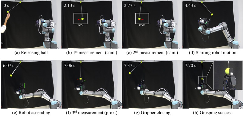
Grasping pendulum at equilibrium point
1. Introduction
Sensor measurements are performed via discrete sampling at specific time points, making it inherently difficult to obtain complete time-series information for phenomena in which the physical quantities continuously change. Therefore, when the sensor sampling frequency is insufficient relative to the rate of change of the target phenomenon, aliasing can occur and the measurement data may misrepresent the actual phenomenon. Therefore, the higher the temporal resolution of the sensor, the more accurate and detailed is the phenomenon that can be captured.
For example, optical proximity sensors provide short-range spatial information and enable compact, high-speed measurements. Hasegawa et al. 1 developed a net-structure proximity sensor (NSPS) that enables high-speed (1 kHz) and free-form measurements by incorporating an analog computing circuit. Such proximity sensors have also been used to enable immediate responses to dynamic environments in robotics. For instance, Arita 2 developed a collision-avoidance system using proximity sensors. Similarly, high-speed cameras provide detailed time-series visual information, and are used for monitoring, analysis, and anomaly detection. Applications include tracking swimming cells (1 kHz) 3, object tracking in dynamic environments (0.5 kHz) 4, the observation of cutting chip formation (5 kHz) 5, and the visualization of plasma spraying phenomena (0.3 MHz) 6, where the tracking of target movements and the elucidation of the mechanisms of complex processes have been realized. Thus, sensors with high temporal resolution can capture steep and instantaneous changes without omission, potentially leading to an understanding of the essential properties of phenomena, such as structural characteristics and causal relationships, rather than mere superficial features.
By leveraging the characteristics of high-speed sensors, improvements in the safety, efficiency, and autonomy of robotic operations can be expected. A representative robotics application is feedback control, which enables immediate responses in dynamic environments. These include reactions to dynamic objects in systems that combine high-speed cameras with high-speed robots 7,8, and gesture recognition 9. However, conventional direct-feedback control requires high-speed robots to respond to high-speed phenomena through tracking, contact, or grasping 10. The range of target dynamics that a robot can handle is fundamentally limited by its motion capabilities, making interactions difficult when there is a large temporal-scale gap between the moving objects and the robot.
Additionally, a single sensor alone may be insufficient for the accurate measurement and prediction of phenomena. For example, some approaches employ a single camera to acquire global and local measurements by changing the observation poses 11. However, high-speed cameras are generally used with a fixed focal length, making flexible measurements difficult. Therefore, sensors suited to different measurement modes (e.g., distance and range) need to be used. For instance, cameras can acquire wide-range information and excel at discovering phenomena and global understanding but are vulnerable to occlusion and lighting conditions. Optical proximity sensors are compact, can be mounted on robot surfaces, and enable the high-speed measurement of nearby areas but have more limited measurement ranges. Integrating multiple sensors with different spatiotemporal characteristics and using them complementarily may lead to more robust and accurate environmental recognition. A generic framework for uniformly handling and integrating heterogeneous sensor information, independent of sensor type and number, is desirable.
The present study addresses these challenges. We proposed a method 12 that extracts task-relevant meta-information about target phenomena from detailed time-series data using high-speed sensors and generates and executes motion plans considering robot temporal constraints. The concept of introducing an information extraction process between sensor measurement and motion planning demonstrates the feasibility of enabling conventional industrial robots to handle high-speed phenomena. However, prior studies lacked a systematic framework for multisensor information integration, requiring task-specific ad hoc implementation.
This study integrated the feature values obtained from each sensor within a single integrated framework independent of the sensor and robot characteristics. Specifically, we introduced the multiple virtual-dynamics-based control (MVDC) proposed by Arita et al. 13 into the information extraction process. MVDC enables the asynchronous integration of information from heterogeneous sensors with different spatial scales and measurement principles by uniformly treating the output of each sensor as a virtual force. The novelty of this study lies in the proposal and demonstration of a unified and generic information extraction framework through the introduction of the MVDC. A simpler alternative, such as explicit switching between sensors based on a predefined transition criterion, would require a manually designed switching logic that is inherently task specific and cannot be generalized. By contrast, MVDC series-connected virtual dynamics allow contributions from heterogeneous sensors to be blended continuously and asynchronously, eliminating the need for explicitly defined switching rules.
To validate the effectiveness of the proposed method, a case study was conducted in which a conventional industrial robot grasped a pendulum. Specifically, sensor information with different characteristics, global measurements using a high-speed camera and local measurements using proximity sensors, was integrated using MVDC to predict the motion period of the target object. Through experiments, we clarified how the sensor information was integrated and reflected in robot motion planning, demonstrating the effectiveness of the proposed method. The main contributions of this study are as follows.
-
This paper proposes a concept that bridges sensor measurement and robot motion planning by introducing an information extraction process.
-
This study developed an information extraction method through the asynchronous integration of heterogeneous sensors using MVDC.
-
The proposed method was practically verified via pendulum-grasping experiments using a conventional industrial robot.
2. Method
2.1. Concept
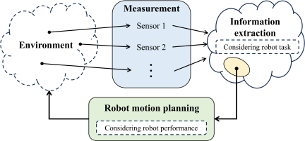
Fig. 1. Conceptual diagram of the proposed method.
The proposed method bridges the temporal-scale gap between high-speed sensors and conventional robots through three separate processes: sensor measurement, information extraction, and motion planning (Fig. 1). Each high-speed sensor independently measures the target phenomena. The information extraction process utilizes high-speed measurement data to extract task-relevant meta-information. The motion planning process generates feasible robot trajectories based on the extracted information and robot constraints.
Our prior study 12 demonstrated this concept but lacked a systematic framework for multi-sensor information integration. This study employed MVDC as an integrated framework.
2.2. Multisensor Information Integration Framework Based on MVDC
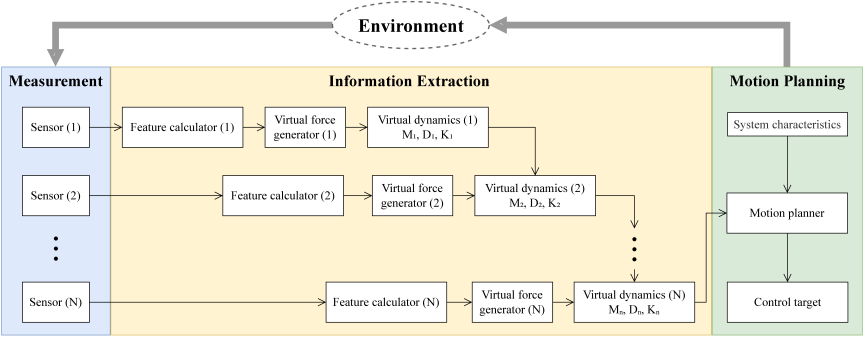
Fig. 2. Multisensor information integration framework based on MVDC. The framework consists of three processes: the measurement process captures sensor data; the information extraction process extracts task-relevant information and integrates them through MVDC; and the motion planning process generates feasible robot trajectories considering system characteristics.
The MVDC proposed by Arita et al. 13 generalizes series admittance-impedance control 14 by introducing the concept of virtual force. The framework treats various sensor outputs uniformly as virtual forces that drive series-connected virtual dynamics (mass–damper–spring models). Each layer responds to virtual forces while treating the previous layer’s output as its equilibrium state, thereby enabling the dynamic integration of information from multiple sensors. The framework offers three key advantages: 1) no switching of control laws, 2) an independent parameter design for each layer, and 3) high modularity for sensor addition. The parameters for each layer can be designed independently, allowing the separate parameterization of the influence of each sensor based on its characteristics. Through a series connection, the influences from all layers accumulate, and the final output reflects their integrated effect. In this study, we extended the applicability of MVDC from motion control to sensor information integration, where the state variables represent task-relevant meta-information rather than physical quantities.
Figure 2 shows the proposed multisensor information integration framework. Multiple sensors measure the target phenomena independently and asynchronously transmit the outputs to the information extraction process. Each sensor output is extracted into task-relevant feature values and then into virtual forces using virtual force generators. These virtual forces drive the respective virtual dynamics (mass–damper–spring models with parameters \(M_i\), \(D_i\), and \(K_i\)). The virtual dynamics are connected in series, where the output of the \(n\)-th layer becomes the integrated value, which is then utilized in the motion planning process to generate robot trajectories. The gains of the virtual force generators and the parameters of the virtual dynamics are designed by considering the measurement characteristics of each sensor (sampling rate and noise level), required response speed, and convergence stability.
The key advantage of this framework is that, by using the concept of virtual force, any sensor output can be handled uniformly, enabling system expansion by simply adding new sensors without modifying the existing virtual dynamics, thus achieving high modularity. Furthermore, as each virtual dynamic can be designed independently, information extraction can be tailored to the sensor characteristics and task requirements by individually adjusting the parameters of each layer. When multiple feature values are necessary for a task, this can be addressed by treating the feature values and virtual forces as vectors or matrices and designing virtual dynamics as multidimensional systems. Regarding the design of MVDC virtual dynamics parameters (mass, damper coefficient, and spring constant), adjustment methods for mass–damper–spring systems in control engineering have been studied for several years, and the existing knowledge can be utilized. By applying established methods, such as parameter design based on critical damping conditions and time constants, adjustment according to sensor characteristics and task requirements can be performed relatively easily, which is an important advantage that enhances the practicality of the proposed method. In our previous approach 12, sensor integration required manually designed switching logic with predetermined priorities. The MVDC framework eliminates this limitation by automatically integrating sensor information through virtual dynamics.
3. System Implementation
3.1. System Configuration
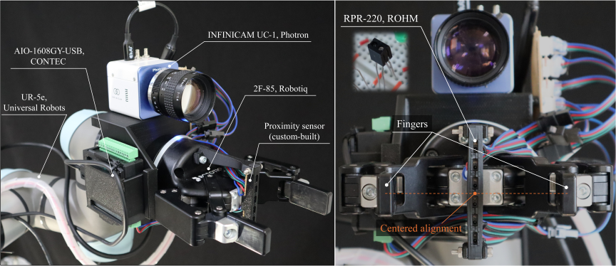
Fig. 3. End-effector configuration with a gripper and proximity sensor module. The sensor element unit consisting of six RPR-220 photoreflectors is mounted on the gripper palm, whereas the analog computing circuit unit is attached to the robot wrist.
The system was constructed by attaching a gripper (2F-85, Robotiq), a high-speed streaming camera (INFINICAM UC-1, Photron), a proximity sensor module, and an analog input USB I/O unit (AIO-1608GY-USB, CONTEC) to an industrial robotic arm (UR5e, Universal Robots).
First, a high-speed camera was used to discover the target phenomena and enable the robot to approach them. However, high-speed cameras inherently involve a tradeoff between resolution and processing time. Maintaining a high resolution during high-speed measurements restricts the field of view. To address this issue, we adopted a hand–eye system to secure a flexible measurement area. As the focal length of the high-speed camera is fixed, the measurement becomes difficult when the robot begins to approach the phenomenon.
Proximity sensors were introduced to perform secondary measurements after the robot approached the target. To accurately measure objects passing through the gripper, we adopted infrared reflective photoreflectors (RPR-220, ROHM), which are compact, have a high temporal resolution, and are suitable for distributed placement on the gripper surface. The design of the proximity sensor module is based on the NSPS proposed by Hasegawa et al. 1, which achieves a high-speed response and measures object center position by connecting multiple sensor elements through a resistor network. The proximity sensor module consists of two parts: a sensor element unit (six RPR-220 units arranged at intervals of 10 mm) and an analog computing circuit unit, which are mounted on the gripper palm and robot wrist, respectively. The computing circuit adds and distributes the currents from each phototransistor and calculates the voltage difference at both ends \(V_1 - V_2\) as the first moment of the photocurrent distribution, thereby measuring the centroid of the object relative to the sensor center. Therefore, an I/O unit was used to sample \(V_1\) and \(V_2\). Fig. 3 shows the end-effector configuration.
3.2. Case Study: Grasping a Pendulum Object
To validate the effectiveness of the proposed method, a case study was conducted in which a conventional industrial robot (UR5e) grasped a pendulum. This task was designed to exemplify the problem setting introduced in Section 1, which inherently requires high-speed sensors to capture the spatiotemporal characteristics of the phenomenon, and the limited response speed of the robot creates a temporal-scale gap that makes direct feedback control impractical.
Specifically, the accurate prediction of the pendulum motion requires detecting the moment when the object passes through its equilibrium point (lowest point), where the velocity changes the most steeply. Sensors with low temporal resolution cannot capture this instantaneous change. With insufficient sampling rates, the object moves significantly between discrete measurements, causing aliasing where peak detection occurs at positions spatiotemporally different from the true timing, leading to significant prediction errors. In contrast, the high-speed camera (1 kHz) and proximity sensor (1 kHz) used in this study could accurately detect these critical moments.
Notably, the proposed method does not rely on the dynamic pendulum system model. Instead, it operates solely on the assumption that the object motion has a constant period. Therefore, the method remains applicable regardless of variations in physical parameters, such as mass, string length, and initial angle, as these values are not assumed to be prior knowledge but are captured implicitly through continuous high-speed measurements. However, the maximum joint velocity of the robot (90°/s) and gripper closing time (approximately 0.44 s) make it difficult to track pendulum motion through direct feedback. Therefore, accurate prediction requires extracting temporal meta-information (periods) from high-speed sensor data and predicting an object’s future arrival time based on this information. Generating motion plans that consider both the predicted future state and robot constraints enables a slow robot to handle fast phenomena, which is the aim of the proposed method.
To maximize the challenge and demonstrate the capability of the method, we intentionally set the grasping point to the equilibrium position where the object velocity is the highest and the tolerance for prediction errors is minimal. The pendulum system provides a structurally simple, yet sufficiently dynamic target for method validation. Despite its simplicity, the task encompassed the core elements of the proposed method: meta-information extraction through high-speed sensing, the integration of heterogeneous sensor information via MVDC, and the generation of feasible trajectories under robot dynamic constraints.
We designed the following three processes to apply the proposed framework to pendulum grasping.
- Measurement Process
-
A high-speed camera and proximity sensor independently measured the pendulum position and passage timing at 1 kHz.
- Information Extraction Process
-
Each sensor independently extracted the period information (\(T_{\mathrm{period}}^{\mathrm{cam}}\), \(T_{\mathrm{period}}^{\mathrm{prox}}\)) from its measurements. The extracted period predictions were integrated using MVDC to obtain the final predicted period.
- Motion Planning Process
-
The feasible grasping time and the trajectory of the motion planning process were determined considering the predicted period and robot constraints (maximum velocity 90°/s, maximum acceleration 90°/s\(^2\), and gripper closing time 0.44 s).
The following sections describe the implementation of these processes.
4. Grasping Motion Planning Based on Multisensor Information Integration
The system consists of four independent threads: camera, proximity sensor, MVDC, and robot control. Each thread operates asynchronously while achieving time synchronization through a unified time management system.
4.1. Period Information Acquisition by Sensors
The high-speed camera performs binary processing and contour detection on the acquired images to track the center of the pendulum. To simplify the motion analysis, the pendulum motion was assumed to be two-dimensional, and the depth distance was estimated using the ball radius and calibration based on the known ball diameter. By dynamically optimizing the region of interest based on the predicted velocity of the object, the computational load can be reduced while achieving high-speed processing. From the time-series data of the \(y\)-coordinates of the detected object, the local maxima (lowest points) were detected to identify when the pendulum passed through the equilibrium point, and the half-period of the pendulum \(T_{\mathrm{period}}^{\mathrm{cam}}\) was calculated from the time difference between the consecutive maxima.
The proximity sensor module sampled the value \(V_1 - V_2\) representing the object centroid relative to the sensor center, at 1 kHz. When the object passes through the gripper, \(V_1 - V_2\) changes its sign from positive to negative (or from negative to positive). By detecting this moment of sign change (i.e., the zero-crossing point), the time at which the object passes through the sensor center is accurately identified. The half-period of the pendulum \(T_{\mathrm{period}}^{\mathrm{prox}}\) was calculated from the time interval between consecutive zero crossings.
The two sensors operate at different spatial scales because of the hand-eye camera configuration. A high-speed camera was mounted on the end effector of the robot with its focal length fixed for distant observation, enabling the discovery of wide-range phenomena and initial period estimation while the robot was at its resting position. However, as described above, once the robot begins approaching the grasping point, the reduced distance to the object causes it to fall outside the depth-of-focus of the camera, rendering camera measurement impossible during the approach and grasping phases. Consequently, because of the limited speed of the robot, camera-based period estimation must be completed well before the grasping execution, as the robot requires time to approach the grasping point. Over this interval, prediction errors accumulate through multiple pendulum cycles, thereby contributing to grasping failure. The proximity sensor directly addressed this fundamental limitation. It was mounted on the gripper itself and measured the passage timing of the object at the grasping point as the pendulum swung through the gripper. This provided a final period of re-estimation immediately before the grasping execution at the precise moment and location where the camera was unable to operate, thereby mitigating the cumulative prediction errors of the long-term camera estimate.
4.2. Period Information Integration Using MVDC
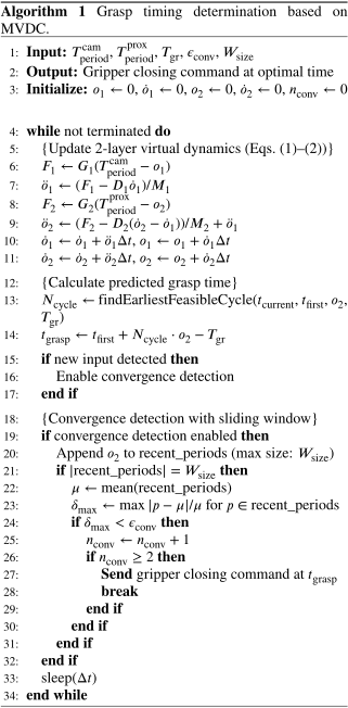
A two-layer virtual dynamics model was constructed to predict the pendulum motion period. The purpose of these virtual dynamics is to integrate period information from multiple sensors and output a predicted period \(\omicron_2\), which is used to determine the grasp timing.
Each layer is represented by a mass–damper–spring model, where \(\omicron_i\) represents the predicted period of the \(i\)-th layer. The virtual dynamics operate as follows. When a sensor input (measured period) differs from the current predicted value \(\omicron_i\), this difference acts as a virtual force that drives the predicted value toward the sensor input. Through this mechanism, the predicted period was continuously updated and converged to a stable value as the virtual dynamics evolved over time.
The virtual dynamics described below do not represent a physical model of the pendulum system. Instead, they serve as a mathematical framework for integrating sensor information. The state variables \(\omicron_i\) represent temporal meta-information, specifically the estimated period for determining the grasping timing. This conceptually differs from physical quantities, such as position or force, as addressed in conventional MVDC research. Virtual dynamics do not generate new meta-information; instead, they integrate already extracted meta-information from multiple sensors and converge it into a single predicted value. This extension expands the applicability of MVDC from motion control to sensor information integration.
The first layer uses the pendulum period \(T_{\mathrm{period}}^{\mathrm{cam}}\) obtained from the high-speed camera as the input, whereas the second layer uses the pendulum period \(T_{\mathrm{period}}^{\mathrm{prox}}\) obtained from the proximity sensor as the input. The virtual dynamics of each layer are described by the following differential equations.
The series-connected structures expressed in Eqs. \(\eqref{eq:eq1}\) and \(\eqref{eq:eq2}\) enable flexible sensor integration independent of the measurement order and timing. The coupling term \(\ddot{\omicron}_1\) in Eq. \(\eqref{eq:eq2}\) allows the first-layer estimate to influence the second-layer estimate. When the camera information arrives first, \(\omicron_1\) converges to \(T_{\mathrm{period}}^{\mathrm{cam}}\) and propagates to \(\omicron_2\) through this coupling. When the proximity sensor information arrives, \(\omicron_2\) updates toward \(T_{\mathrm{period}}^{\mathrm{prox}}\) while incorporating the camera information. In general, whenever a new measurement arrives from either sensor, the estimate is updated automatically at that moment, regardless of the order in which the sensors provide the information. This design eliminates the need for manual switching logic, which depends on which sensor first provides the data.
At equilibrium (when \(\ddot{\omicron}_1 = \dot{\omicron}_1 = 0\) and \(\ddot{\omicron}_2 = \dot{\omicron}_2 = 0\)), Eq. \(\eqref{eq:eq1}\) yields \(\omicron_1 = T_{\mathrm{period}}^{\mathrm{cam}}\) and Eq. \(\eqref{eq:eq2}\) yields \(\omicron_2 = T_{\mathrm{period}}^{\mathrm{prox}}\), indicating that the second-layer output converges to the proximity sensor measurement. The virtual dynamics parameters of each layer were set as \(M_1=M_2=0.1\), \(D_1=D_2=2.8\), \(G_1=G_2=40.0\), with a numerical integration step size of \(\Delta t= 0.01\) s, which corresponds to the lower limit achievable on standard Windows OS. In practice, the actual update interval is approximately 15–16 ms (62–65 Hz) owing to the OS thread-scheduling overhead. Despite this lower MVDC update rate, the high-speed information required by the proposed method was fully utilized. The system comprised four independent operating parallel threads: a camera thread (1 kHz), proximity sensor thread (1 kHz), MVDC thread (100 Hz), and robot control thread. Period extraction was performed entirely within the dedicated sensor threads at 1 kHz, and the resulting period estimates were passed to the MVDC thread for each detection event. Therefore, the integration step size \(\Delta t= 0.01\) s for MVDC is independent of the sensor sampling rate. The mass–damper–spring parameters \(M_i\), \(D_i\), \(G_i\) were designed based on a well-established damping ratio \(\zeta = 1/\sqrt{2}\) (approximately 0.707), which is known to achieve the fastest convergence while allowing a moderate overshoot. As the predicted period \(\omicron_2\) determines the grasp timing rather than the robot tracking trajectories, transient overshoots are acceptable, making this damping ratio suitable for period prediction.
4.3. Determination of Gripper Grasp Timing
Algorithm 1 shows the pseudocode for determining the grasping timing based on MVDC. The MVDC thread continuously updates the predicted period \(\omicron_2\) and determines the earliest feasible grasping cycle \(N\) after the current time based on the first valid input time \(t_{\mathrm{first}}\). The start time of the grasping action is calculated as \(t_{\mathrm{grasp}} = t_{\mathrm{first}} + N \cdot \omicron_2 - T_{\mathrm{gr}}\), which is the predicted \(N\)-th equilibrium passage time minus the gripper response time \(T_{\mathrm{gr}}\).
When new sensor measurements become available (i.e., when \(T_{\mathrm{period}}^{\mathrm{cam}}\) or \(T_{\mathrm{period}}^{\mathrm{prox}}\) is updated), the virtual dynamics respond and the predicted period \(\omicron_2\) changes dynamically, necessitating convergence detection. In this method, the most recent \(W_{\mathrm{size}}\) predicted periods were monitored, and convergence was determined when the maximum relative deviation from the mean value fell below a threshold \(\epsilon_{\mathrm{conv}}\). In these experiments, \(W_{\mathrm{size}}=10\) and \(\epsilon_{\mathrm{conv}}=1\%\) were used. Convergence detection was enabled when a new measurement was obtained; after the first convergence following the camera measurement and the second convergence following the proximity sensor measurement, the integration of information from both sensors was confirmed.
4.4. Robot Trajectory Generation and Grasp Execution
In trajectory planning, smooth trajectories are generated using fifth-order polynomials in joint space. The trajectory was designed to satisfy the kinematic constraints of the robot, including the joint position range, maximum velocity, and maximum acceleration. The trajectory was divided into two stages: approach and grasping. In the approach stage, to avoid collision between the robot and pendulum trajectories, an intermediate position with a height offset added to the target position of the grasping stage was used. This intermediate position allowed the gripper to enter from below the pendulum trajectory, thereby enabling the object to pass safely between the gripper fingers. In the grasping stage, the robot moved from an intermediate position to the grasping position. When the start time of the grasping action \(t_{\mathrm{grasp}}\) determined by the MVDC (Section 4.3) was sent to the gripper, it waited until the specified time and then executed the grasping action.
5. Experiments
5.1. Experimental Setting
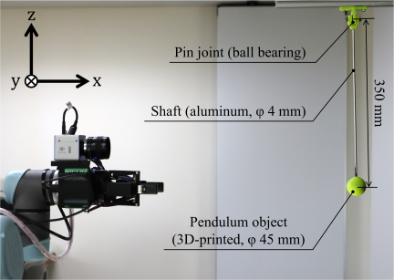
Fig. 4. Experimental setup with a UR5e robot manipulator and pendulum object. The pendulum system consists of a pin joint, an aluminum shaft, and a 3D-printed PLA ball (diameter: 45 mm, mass: 39 g) with a pendulum length of 350 mm from the pin joint center to the ball center. The robot base coordinate system is illustrated with labeled axes: the \(X\)-axis points horizontally toward the pendulum system, the \(Z\)-axis points vertically upward, and the \(Y\)-axis follows the right-hand rule. The origin is at the center of the robot base mounting surface on the first joint axis.
Figure 4 shows the configuration of the experimental system. To physically realize the two-dimensional planar pendulum motion assumed in the task setting, a pendulum system was constructed using a pin joint with ball bearings as the rotation center and a rigid aluminum shaft connecting the joint to the pendulum object. This mechanical design constrained the pendulum motion to a single vertical plane. The high-speed camera was set to a frame rate of 1000 fps, a shutter speed of 1/2000 s, and a resolution of 1246\(\times\)1008. The proximity sensor module was sampled at 1 kHz. The gripper was operated at a fingertip velocity of 100 mm/s and a grasping force of 200 N. The kinematic constraints of the robot included a maximum joint range of motion of 180°, a maximum joint velocity of 90°/s, and a maximum joint acceleration of 90°/s\(^2\).
5.2. Results
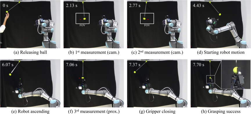
Fig. 5. Experimental sequence of pendulum grasping. (a) Releasing the pendulum ball to initiate periodic motion. (b) First measurement by the high-speed camera (1000 fps) detecting the pendulum passing through the equilibrium point and acquiring the initial time information. (c) Second measurement by the camera calculating the half-period \(T_{\mathrm{period}}^{\mathrm{cam}}\) from consecutive peak detections, which is input to MVDC layer 1 for period prediction. (d) Robot motion initiation after the period information is obtained from the camera, moving toward the grasp position following a quintic polynomial trajectory. (e) Robot ascending via the intermediate position with height offset to avoid collision with the pendulum trajectory, maintaining an open gripper for safe passage. (f) Third measurement by the proximity sensor module detecting the zero-crossing of \(V_1 - V_2\) as the object passes through the gripper, calculating \(T_{\mathrm{period}}^{\mathrm{prox}}\), which is input to MVDC layer 2 for the prediction of final integrated period prediction. (g) Gripper closing execution based on the predicted timing after MVDC convergence, closing at 100 mm/s to catch the pendulum at the next equilibrium passage. (h) Successful grasping of the pendulum object at the equilibrium point, demonstrating the feasibility of high-speed object manipulation by the conventional industrial robot through sensor information integration and precise motion planning.
Figure 5 shows the snapshots of the pendulum-grasping experiment. After releasing the pendulum object (Fig. 5(a)), the high-speed camera detected the first (Fig. 5(b)) and second equilibrium passages (Fig. 5(c)), from which the half-period \(T_{\mathrm{period}}^{\mathrm{cam}}\) was calculated and input to the first layer of the MVDC. Once the period information from the camera was obtained, the robot began moving toward the grasping position (Fig. 5(d)) and ascended via an intermediate position (Fig. 5(e)). When the robot approached the grasping position, the proximity sensor module detected the equilibrium passage (Fig. 5(f)), and the half-period \(T_{\mathrm{period}}^{\mathrm{prox}}\) was calculated and input to the second layer of the MVDC. After the convergence of the integrated period prediction from both sensors, the gripper closing action was executed at the predicted grasping timing (Fig. 5(g)), and grasping at the equilibrium point (lowest point) was successful (Fig. 5(h)).
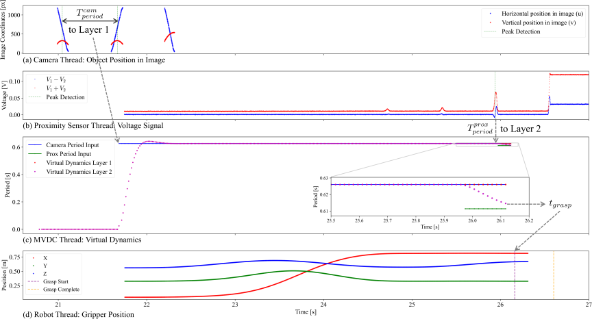
Fig. 6. Unified timeline of multithread data integration. (a) Camera thread: horizontal (\(u\)) and vertical (\(v\)) positions of the object in the image coordinates sampled at 1000 fps, with the green dashed lines indicating peak detection when the pendulum passes through the equilibrium point, from which the half-period \(T_{\mathrm{period}}^{\mathrm{cam}}\) is calculated. (b) Proximity sensor thread: voltage signals representing the object centroid position (\(V_1 - V_2\), blue) and detection intensity (\(V_1 + V_2\), red) sampled at 1 kHz, with the green dashed lines showing zero-crossing detection when the object passes through the sensor center (gripper center), from which \(T_{\mathrm{period}}^{\mathrm{prox}}\) is calculated. (c) MVDC thread: virtual dynamic responses showing period inputs from the camera (blue) and the proximity sensor (green), with outputs from layer 1 (red) and layer 2 (purple) demonstrating the integration of heterogeneous sensor information through the two-layer mass–damper–spring model and convergence to the final period prediction. (d) Robot thread: gripper position trajectory in the robot base coordinates showing \(X\) (red), \(Y\) (green), and \(Z\) (blue) positions, with the purple dashed line indicating the gripper closing start time and the orange dashed line indicating the completion time, demonstrating object capture at the optimal timing predicted by MVDC at approximately 26 s.
Figure 6 shows the timeline of each thread referenced to the start time of the program. The four independent threads (camera, proximity sensor, MVDC, and robot control) operated asynchronously and were time-synchronized through unified time management. After the start of the program, system initialization and robot initial posture setting were performed, and approximately 20 s later, the pendulum object was manually released to begin the experiment. The operation of each thread is explained below, along with a quantitative analysis of the experimental data in chronological order.
In Fig. 6(a), the object position in the image coordinates was sampled at 1000 fps, and the half-period \(T_{\mathrm{period}}^{\mathrm{cam}}\) was calculated by peak detection. In the experiment, the first peak detection after the pendulum release was performed at 21.051 s, capturing the moment when the pendulum passed through the lowest point (equilibrium point). The second peak was detected at 21.677 s (0.626 s after the first), and the camera-based half-period \(T_{\mathrm{period}}^{\mathrm{cam}} = 0.626\) s was calculated from this time difference. After estimating the period from these two peaks, the robot began moving toward the grasping position, and the subsequent peaks (third and later) were not used for the period calculation. As the high-speed camera was mounted on the end effector of the robot, it moved simultaneously with the robot during the approach phase, causing the relative position between the camera and the object to change. Consequently, the image coordinates of the subsequent peaks were recorded at different heights, not because the trajectory of the object changed, but because the camera itself was moving. This is an unavoidable phenomenon in hand-eye systems and does not affect the period estimation accuracy because the period has already been calculated from the first two peaks acquired while the robot is stationary.
In Fig. 6(c), information from different sensors was integrated through two-layer virtual dynamics. When the period information obtained from the camera was input to the first layer of the MVDC (red line), period prediction began through virtual dynamics. At this point, the predicted grasping time was calculated to be 26.059 s (8th cycle).
In Fig. 6(b), the voltage signals \(V_1 - V_2\) (blue line) and \(V_1 + V_2\) (red line) were measured at 1 kHz, and the half-period \(T_{\mathrm{period}}^{\mathrm{prox}}\) was calculated using zero-crossing detection. In this experiment, the initial peak detection was performed at 25.941 s. This time was 0.118 s earlier than the predicted passage time of 26.059 s based on the camera-only prediction, indicating that the camera-alone period prediction could not accurately capture the actual pendulum motion. The time difference from the first camera peak was 4.891 s, and from this time difference and the camera period of 0.626 s, the pendulum was predicted to have completed approximately 7.813 oscillations (\(4.891/0.626=7.813\) s). Using the nearest integer number of oscillations (8), the proximity-sensor-based period was calculated as \(T_{\mathrm{period}}^{\mathrm{prox}} = 4.891/8 = 0.611\) s.
When this period information was input to the second layer of the MVDC (purple line), the camera and proximity sensor information was integrated and converged at 26.120 s. At this point, the predicted period was 0.615 s with a variation rate of 0.893%, satisfying the convergence criterion (below 1%). Upon detecting the second convergence, the MVDC thread sent a command for a grasping time of 26.163 s to the gripper control thread.
In Fig. 6(d), the gripper position trajectories (\(X\): red, \(Y\): green, \(Z\): blue) are shown, along with the grasping start and completion times. After waiting 0.043 s until the specified time, the gripper closing action began at 26.163 s (purple dashed line) and grasping was completed at 26.603 s, approximately 0.44 s later (orange dashed line).
Thus, the proposed method realized pendulum grasping through the following processes: (1) initial period prediction from global measurement by the camera (0.626 s), (2) accurate period prediction integrating local measurement by the proximity sensor (0.611 s \(\to\) 0.615 s), (3) convergence determination and optimal grasping timing determination by the MVDC (26.163 s), (4) successful grasping through accurate timing control. Compared with the camera-only prediction (0.626 s), integrating the proximity sensor improved the period prediction accuracy (0.615 s), enabling a more accurate prediction of grasping timing.
Comparative experiments were conducted over multiple trials to evaluate the robustness and effectiveness of the proposed method under varying initial conditions. We performed 20 trials for both the visual-only approach (camera-based period estimation) and proposed method (MVDC-based sensor integration). The pendulum was manually released from different initial angles during each trial to ensure diverse initial conditions.
The experimental results were as follows: the visual-only approach achieved 8 successes out of 20 trials (40% success rate), whereas the proposed method achieved 12 successes out of 20 trials (60% success rate). The proposed method demonstrated a 50% improvement in the success rate compared with the visual-only approaches. This improvement validates the effectiveness of integrating heterogeneous sensor information using an MVDC framework.
6. Discussion
The essence of this study is not the grasping of pendulum objects themselves, but rather the proposal of a general framework that bridges the temporal-scale gap between high-speed sensors and robots through an information extraction process. To validate the effectiveness of the proposed concept (Fig. 1), we conducted a case study involving pendulum grasping. In this section, we discuss the effectiveness, applicability, and challenges of the proposed framework based on experimental results.
6.1. Effectiveness of Proposed Framework
First, we discuss the effectiveness of the information extraction process using the MVDC. As shown in Fig. 6(c), the period information from the sensors with different characteristics (high-speed camera and proximity sensor) was integrated through two-layer virtual dynamics and converged to the final period prediction. This result demonstrates that the MVDC can asynchronously integrate heterogeneous sensor information with different spatial scales and measurement principles. In particular, combining global measurement by a camera and local measurement by a proximity sensor has the potential to achieve a more robust period prediction than using a single sensor. The virtual dynamic architecture of MVDC achieves this continuous integration without explicit switching logic, rather than manually specifying when to transition from camera-based to proximity-sensor-based information; the series-connected virtual dynamics naturally blend the two contributions as sensor inputs arrive asynchronously.
Subsequently, we compared the proposed method with the conventional approaches. In conventional high-speed robot systems 10, the direct feedback control of dynamic objects is possible owing to the high-speed responsiveness of the robot. However, in this study, we used a conventional industrial robot (a maximum joint velocity of 90°/s), which made it difficult to respond to dynamic phenomena using direct feedback control. The proposed method overcomes this temporal-scale gap by extracting period information from detailed time-series data using high-speed sensors and predicting the optimal grasping timing based on this information. As shown in Fig. 5(h), the successful grasping at the equilibrium point, which is the most difficult position, is an important achievement that demonstrates the effectiveness of the proposed method. Note that the focus of conventional high-speed sensor studies is different from that in this study. Conventional approaches focus on realizing high-speed robot motions that can directly exploit fast sensors, whereas this study focused on methods that effectively utilize high-speed sensor information for robots with limited motion speeds. Given these fundamentally different objectives and problem settings, a direct performance comparison of the two approaches is difficult.
6.2. Applicability and Generalizability
The proposed framework is not limited to the specific task of pendulum grasping and can be applied to a wider range of high-speed tasks. It is important to extract meta-information about target phenomena from detailed time-series data using high-speed sensors and generate motion plans for conventional industrial robots based on that information. For example, this framework may be applicable to various tasks in which there is a temporal-scale gap between the sensors and robots, such as assembly work on vibrating objects or collaborative work with high-speed moving objects.
Importantly, the meta-information extracted by the proposed method is not necessarily used only for the future prediction of the target phenomena. It is also applicable for adaptively determining the state and actions of a robot based on phenomena observed in time-series information. For example, in coating work, by measuring liquid droplet bounce behavior with a high-speed sensor and predicting the thickness distribution of the liquid film from the time-series information, adaptive action planning according to the work state becomes possible, such as coating thinner areas more thickly. Thus, the proposed framework is flexible and applicable not only to future-prediction-type tasks but also to tasks requiring state prediction and adaptive control based on phenomenon observation.
From a practical perspective, the high-speed camera and proximity sensor used in this study have undergone miniaturization and cost reduction owing to recent technological advances, and the barriers to their introduction into industrial robot systems are decreasing. By applying the proposed method to existing industrial robots, the ability to respond to high-speed phenomena can be improved without accelerating the robot body itself, which is important from the perspective of the effective utilization of existing equipment.
6.3. Limitations and Future Challenges
In this case study, we selected the period characteristic based on the prior knowledge of the nature of the phenomenon, assuming that pendulum motion is a periodic phenomenon. For more complex aperiodic or unknown phenomena, it is difficult to identify which meta-information is necessary for task execution, and the selection of meta-information itself requires task-specific expertise. Developing methods for discovering and selecting the required meta-information is an important future challenge. However, once the appropriate meta-information is identified, the information processing design for extracting it (feature calculation and MVDC parameter adjustment) can be performed relatively systematically.
In addition, both sensors were operated at a sampling rate of 1 kHz. As the MVDC is designed to accept sensor inputs asynchronously through virtual dynamics, the framework is theoretically applicable to sensors with different sampling rates. The experimental validation of this multirate sensor integration capability is a future challenge.
7. Conclusion
This study developed a motion planning method for conventional industrial robots that bridges the temporal-scale gap between high-speed sensors and robots. The core concept is to introduce an information extraction process between sensor measurement and motion planning, which extracts task-relevant meta-information from high-speed sensor data to enable feasible motion planning within robot constraints.
We introduce MVDC as a unified framework for the information extraction process, enabling the asynchronous integration of heterogeneous sensor information with different spatial scales and measurement principles. Through a pendulum-grasping experiment, we demonstrated that the proposed method successfully enabled a conventional industrial robot (UR5e) to grasp an object at its equilibrium point by integrating high-speed camera (1000 fps) and proximity sensor (1 kHz) measurements using MVDC.
Acknowledgments
This study was partially supported by JSPS KAKENHI (Grant Number: JP24H00726).
- [1] H. Hasegawa, Y. Suzuki, A. Ming, K. Koyama, M. Ishikawa, and M. Shimojo, “Net-Structure Proximity Sensor: High-speed and free-form sensor with analog computing circuit,” IEEE/ASME Trans. Mechatron., Vol.20, No.6, pp. 3232-3241, 2015. https://doi.org/10.1109/TMECH.2015.2417555
- [2] H. Arita, “A fast optical proximity sensor skin that contains an analog computing circuit and can cover an entire link,” Adv. Robot., Vol.37, No.17, pp. 1083-1099, 2023. https://doi.org/10.1080/01691864.2023.2239320
- [3] K. Yamato, H. Chiba, and H. Oku, “High speed three dimensional tracking of swimming cell by synchronous modulation between TeCE camera and tag lens,” IEEE Robot. Autom. Lett., Vol.5, No.2, pp. 1907-1914, 2020. https://doi.org/10.1109/LRA.2020.2969911
- [4] M. Jiang, K. Shimasaki, S. Hu, T. Senoo, and I. Ishii, “A 500-fps pan-tilt tracking system with deep-learning-based object detection,” IEEE Robot. Autom. Lett., Vol.6, No.2, pp. 691-698, 2021. https://doi.org/10.1109/LRA.2020.3048653
- [5] Y. Guo, W. D. Compton, and S. Chandrasekar, “In situ analysis of flow dynamics and deformation fields in cutting and sliding of metals,” Proc. Roy. Soc. A, Vol.471, No.2178, Article No.20150194, 2015. https://doi.org/10.1098/rspa.2015.0194
- [6] K. Bobzin, M. Öte, M. A. Knoch, I. Alkhasli, and H. Heinemann, “High-speed video analysis of the process stability in plasma spraying,” J. Therm. Spray Technol., Vol.30, pp. 987-1000, 2021. https://doi.org/10.1007/s11666-021-01159-1
- [7] T. Senoo, A. Namiki, and M. Ishikawa, “High-speed batting using a multi-jointed manipulator,” Proc. IEEE Int. Conf. Robot. Autom. (ICRA), pp. 1191-1196, 2004. https://doi.org/10.1109/ROBOT.2004.1307986
- [8] S. Morikawa, T. Senoo, A. Namiki, and M. Ishikawa, “Realtime collision avoidance using a robot manipulator with light-weight small high-speed vision systems,” Proc. IEEE Int. Conf. Robot. Autom. (ICRA), pp. 794-799, 2007. https://doi.org/10.1109/ROBOT.2007.363083
- [9] K. Ito, T. Sueishi, Y. Yamakawa, and M. Ishikawa, “Tracking and recognition of a human hand in dynamic motion for janken (rock-paper-scissors) robot,” Proc. IEEE Int. Conf. Autom. Sci. Eng. (CASE), pp. 891-896, 2016. https://doi.org/10.1109/COASE.2016.7743496
- [10] M. Ishikawa, “High-Speed Vision and its Applications Toward High-Speed Intelligent Systems,” J. Robot. Mechatron., Vol.34, No.5, pp. 912-935, 2022. https://doi.org/10.20965/jrm.2022.p0912
- [11] H. Chen, T. Kiyokawa, W. Wan, and K. Harada, “Adaptive Grasping of Moving Objects in Dense Clutter via Global-to-Local Detection and Static-to-Dynamic Planning,” Proc. IEEE Int. Conf. Robot. Autom. (ICRA), pp. 14059-14065, 2025. https://doi.org/10.1109/ICRA55743.2025.11127936
- [12] M. Koreki, U. Chuluunbat, H. Arita, K. Nakashima, and K. Tahara, “Motion Planning Leveraging High-Speed Sensors for Conventional Industrial Manipulator,” Proc. IEEE/SICE Int. Symp. Syst. Integr. (SII), pp. 1483-1489, 2026. https://doi.org/10.1109/SII64115.2026.11404605
- [13] H. Arita, H. Nakamura, T. Fujiki, and K. Tahara, “Smoothly Connected Preemptive Impact Reduction and Contact Impedance Control,” IEEE Trans. Robot., Vol.39, No.5, pp. 3536-3548, 2023. https://doi.org/10.1109/TRO.2023.3286045
- [14] T. Fujiki and K. Tahara, “Series admittance–impedance controller for more robust and stable extension of force control,” Robomech J., Vol.9, Article No.23, 2022. https://doi.org/10.1186/s40648-022-00237-5
This article is published under a Creative Commons Attribution-NoDerivatives 4.0 Internationa License.