
Paper:
Double-Roller Tactile Image Sensor for Simultaneous Double-Sided Inspection
Tomomi Murata and Kazuhiro Shimonomura
Department of Robotics, Ritsumeikan University
1-1-1 Nojihigashi, Kusatsu, Shiga 525-8577, Japan

This paper proposes a surface inspection method using a double-roller tactile image sensor. The roller-type tactile image sensor provides high spatial resolution by employing a camera and enables continuous contact with the object surface via the rollers. However, a single sensor can acquire a contact image from only one side of the object. To address this limitation, we developed a double-roller tactile image sensor capable of capturing contact images from both sides by sandwiching the object between two rollers. The relationship between applied force and image response was investigated through sensitivity experiments using a force gauge and nylon thread. Experiments using models simulating food and foreign objects revealed that a sufficiently large response was obtained with a pressing force of 0.1 N even for small objects with a diameter of 0.25 mm, while differences in material hardness and foreign object size resulted in differences in the contact image. Furthermore, we performed an experiment using shrimp as an example of food inspection and confirmed that the proposed sensor can successfully capture images of shell fragments remaining on the shrimp.
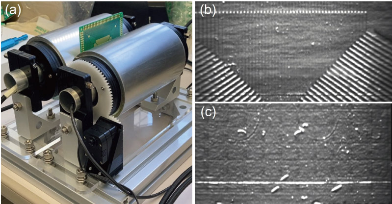
Double roller tactile image sensor (a) and output images (b, c)
1. Introduction
Surface inspection plays a crucial role in quality control within manufacturing processes, as it aims to detect defects present on product surfaces. In automated surface inspection, non-contact optical methods—such as camera-based sensing—are generally preferred to ensure that the inspection process itself does not affect product quality 1. However, when the defects to be detected cannot be distinguished from normal regions using non-contact methods, alternative inspection techniques become necessary. For example, in the food manufacturing industry, determining whether all shells have been removed from raw shrimp is difficult with camera-based inspection, so human inspectors typically rely on visual observation and tactile feedback to identify remaining shells. In particular, when the goal is to detect hard foreign objects mixed within soft food products, tactile, contact-based inspection is often highly effective.
Tactile sensing in humans is distributed in an array-like manner to capture the position and shape of contact areas. A tactile sensor with performance comparable to that of a human fingertip should provide a spatial resolution of approximately 1 to 2 mm and incorporate 50 to 100 sensing points 2. Furthermore, human tactile perception can detect height variations on the submillimeter scale. Depending on the type of product, certain inspection tasks rely on the extremely high tactile sensitivity of the human hand. To automate such inspection tasks, a tactile sensor with both high spatial resolution and high sensitivity is essential 3, and the development of various tactile sensors and their applications have been studied 4,5,6.
Tactile sensors capable of obtaining high spatial resolution and rich information using a camera have been proposed. These sensors are commonly referred to as tactile image sensors or vision-based tactile sensors 7,8,9. A variety of tactile image sensors have been developed to date, and new designs continue to be proposed. Our research group has developed several tactile image sensors, which we have primarily employed for robotic hand grasping control and manipulation tasks 10,11. Tactile image sensors generally consist of a camera and a tactile skin that converts physical contact into an optical signal detectable by the camera. Depending on how contact is converted into optical information, these sensors can be classified into several types 12. For example, the marker displacement method is one of the most widely used approaches, in which a camera measures the displacement of visual markers embedded in a soft material 13,14,15. This method is particularly suitable for detecting the magnitude and direction of applied forces. In the reflective membrane method, a camera captures small deformations on the surface of a flexible sheet covered with a reflective membrane 16,17. Because minute irregularities on the sensor surface are emphasized by illumination applied from the side, even very small surface features, such as human fingerprints, can be visualized. Reflective membrane-type tactile image sensors thus have the potential to detect extremely small defects and are particularly suitable for contact-based surface inspection.
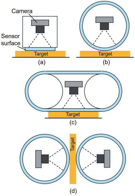
Fig. 1. Sensor shape and configuration of tactile image sensors for inspection. (a) Flat, the most common shape, (b) roller 18,19, (c) belt 20, and (d) double-roller in this work. Only the proposed method is capable of simultaneously acquiring tactile images of both the front and back surfaces of the object.
In order to efficiently perform contact inspection of the object to be inspected, it is necessary to consider the shape and configuration of the sensor. Fig. 1 shows typical sensor shape and configuration. Most tactile image sensors proposed to date have been designed primarily for robotic manipulation and are therefore intended to be mounted on the fingertips of robot hands 21. Consequently, they are typically compact and feature relatively flat contact surfaces. In recent years, sensors with curved geometries that more closely resemble the human fingertip have also been developed 22,23,24. For inspection-oriented applications, however, the use of such fingertip-type sensors requires the sensor to be moved up and down repeatedly to sequentially touch multiple inspection points one by one. As a result, when inspecting a large surface area or a large number of objects, this approach becomes time-consuming, and these sensor shapes are not necessarily efficient. To address this issue, a roller-type tactile image sensor was proposed, in which a camera is placed inside a cylindrical sensing surface 18,19. This sensor geometry is well suited for surface inspection, as it enables rapid, continuous inspection by rolling the sensor surface across large inspection areas or over surfaces where many objects are arranged. Furthermore, a belt-type tactile image sensor was proposed, in which a looped belt-shaped sensing surface is rotated by two wheels 20. In the roller-type sensor, the contact area at any given moment is relatively small; therefore, when the defect pattern on an object’s surface needs to be captured, it is necessary to roll the sensor to scan the surface while generating a composite image. Because the belt-type sensor provides a larger contact area, it enables efficient use of the camera’s field of view and allows direct visualization of surface height or defect patterns without requiring image compositing.
All of the tactile image sensors described above can inspect only one side of an object—the side that comes into contact with the sensing surface. For plate-like objects such as printed circuit boards or fiber sheets, or for granular food items such as shrimp or shellfish, defects located on the backside cannot be detected unless the object is flipped over by some means. This requirement introduces an additional and cumbersome step in automated inspection processes.
In this study, we developed a double-roller tactile image sensor in which two roller-type sensors are arranged facing each other to enable simultaneous inspection of both the front and back surfaces of a target object (Fig. 2). This configuration allows simultaneous detection of defects on both sides of plate-like objects such as printed circuit boards, as well as the simultaneous inspection of foreign materials on both sides of food items such as shrimp.
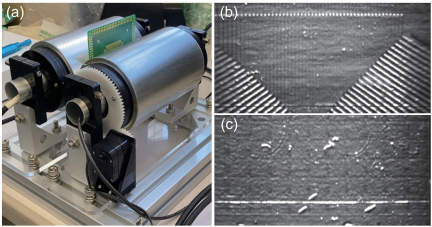
Fig. 2. Double roller tactile image sensor developed in this study. An object (printed circuit board in this figure) is sandwiched between two rollers (a), and the surface microstructures of both the front and back surfaces are simultaneously acquired (b, c).
2. Double Roller Tactile Image Sensor
2.1. Tactile Sensing Principle
A tactile image sensor consists of a sensing surface that comes into contact with the target object, a camera that captures the sensing surface from behind, and a computer that analyzes the camera images to extract tactile information. The sensing surface includes a mechanism that converts the physical contact of an object into optical information so that the contact-induced changes can be observed in the camera images. The spatial and temporal resolution of the tactile sensor is essentially determined by the specifications of the camera and the performance of the image-processing algorithms.
Various methods have been proposed for converting physical contact on the sensing surface into optical information 7. In this study, we adopt the reflective-membrane method, which is particularly well suited for inspection applications 16,17. The structure of a tactile imaging sensor based on this reflective-membrane method is shown in Fig. 3. The sensing surface that contacts the object is made of a transparent, soft elastic sheet. A thin reflective membrane is formed on the outer surface of this sheet. The reflective membrane serves to reflect light from a light source and generate shading that corresponds to the surface’s minute height variations. Ideally, the membrane should be uniform in color and as thin as possible; for example, it can be created by coating the surface with a thin layer of silver paint.
When an object contacts the surface of the elastic sheet coated with a reflective membrane, the soft material deforms according to the surface geometry of the object. The transparent elastic sheet is bonded to a light-guiding plate (e.g., a transparent acrylic plate) that incorporates illumination sources along its edges, forming an edge-lit light-guiding illumination system. Light emitted from the sources propagates through the light-guiding plate and the transparent elastic layer, illuminating the reflective membrane from behind. The camera captures the resulting deformation pattern of the reflective membrane, which is emphasized by variations in surface height and therefore becomes clearly visible in the images. This configuration enables the capture of fine surface features; for example, the system can visualize the ridges and valleys of a human fingerprints.
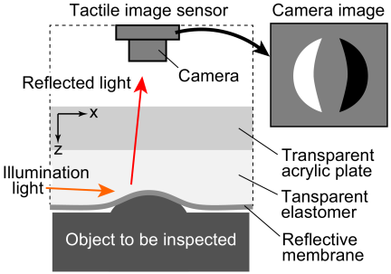
Fig. 3. Principle of tactile sensing in the tactile image sensor with reflective-membrane method. Small bumps on the object’s surface cause deformations in the soft sensor surface, which are visualized as patterns of shadows in the camera image.
2.2. Structure of the Sensor
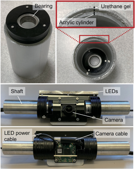
Fig. 4. Structure of the roller-type tactile image sensor. The cylindrical roller is covered with a layer of flexible, transparent urethane gel coated with a reflective film on the surface of a transparent acrylic tube. A camera and LED illumination are mounted on a shaft inside the roller.
Figure 4 shows the structure of the two roller-type sensors that constitute the double-roller tactile image sensor. The roller-shaped sensing surface is constructed by attaching a urethane-gel sheet (Asker C23, thickness 5 mm) onto an acrylic cylinder (length 150 mm, thickness 3 mm), and then coating the outer surface with silver paint to form a reflective membrane. In addition, a transparent film dressing (Tegaderm, 3M) is applied to protect the reflective membrane. The outer diameter of the roller is 80 mm. An aluminum hollow shaft (outer diameter 24.96 mm) is mounted along the rotational axis of the roller, and both a white LED and a camera are installed on this shaft. The camera used is a CMOS model, IDS UI-3481LE-M-GL (\(2560 \times 1920\) pixels, monochrome). The camera cable and LED power cable pass through the inside of the hollow shaft and can be routed to the outside of the roller. The black resin components that fix the camera to the side cover and shaft are fabricated by laser-cutting acrylic plates and assembling them through stacking and bonding. The black side cover contains an O-ring, which is held in place by the friction generated between the O-ring and the roller. Bearings are also implemented as axle supports to reduce friction between the cover and the shaft.
Figure 5 illustrates the overall structure of the double-roller sensor. Two rollers with the same construction described above are fixed onto an aluminum frame. One of the rollers is mounted at the end of the aluminum frame, while the position of the other roller can be adjusted manually to change the spacing between the two rollers. The fixed roller serves as the driving roller and is rotated by a servo motor. The driving roller and the servo motor are equipped with spur gears, which transmit the rotation of the servo motor to the roller. The spur gear on the roller side is made of polyacetal resin and has 68 teeth. The servo motor side consists of the servo motor, a planetary gear set, and a spur gear. The servo motor used is KRS-3301 ICS (Kondo Kagaku Co., Ltd., maximum torque 4.9 kg\(\cdot\)cm, maximum speed 62.5 rpm). Two planetary gear units with a \(4:1\) gear ratio are stacked to achieve an overall \(16:1\) reduction. The spur gear on the servo motor side is also made of polyacetal resin and has 34 teeth.
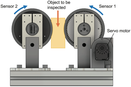
Fig. 5. Structure of the double-roller tactile image sensor. Two roller-type sensors are fixed facing each other. The object under inspection is placed between the two rollers, and as the rollers rotate, tactile images of both the front and back surfaces of the object are acquired simultaneously and continuously.
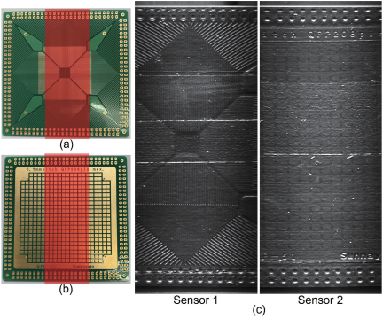
Fig. 6. Output images of the double-roller tactile image sensor. Tactile images of both the front and back surfaces of the IC conversion board were acquired simultaneously. While rotating the rollers, images were continuously captured, and 12 lines of the image were extracted from each frame (the method for determining the width is described in the main text) and concatenated to generate a tactile image of the entire object.
2.3. Output Images
Figure 6 shows the output of the double-roller tactile imaging sensor. Both the front and back surfaces of an IC conversion board were captured simultaneously. The grayscale images obtained by the camera are first corrected for lens distortion through camera calibration. At any given instant, only a limited portion of the object is in contact with the roller-shaped sensing surface. To generate contact images over a larger area, the roller is rotated at a constant speed, and the regions corresponding to contact in each captured image are cropped to a fixed width and then sequentially concatenated.
The relationship between the required cropping width and the roller rotation speed is given by the following equation,
In generating the output image, we assume that there is sufficient friction between the roller and the object to prevent slippage. If slippage does occur, the object will not move even though the roller is rotating, and the output image is expected to be distorted in the vertical (\(y\)) direction. In the output image shown in Fig. 6(c), the object (IC conversion board) has texture at regular intervals, and this texture is also at regular intervals in the vertical direction in the output image (see output image of Sensor 2), indicating that there is no slippage or that the slippage is negligibly small in this case.
3. Evaluation of the Sensitivity
3.1. Experimental Setup
The double-roller tactile image sensor acquires tactile images by grasping an object from both sides with two rollers and applying force. Understanding how the sensor’s response varies depending on the applied force and the properties of the object allows us to determine the applicable range of the sensor. To this end, we investigated the relationship between the thickness of foreign particles, the hardness of the object, and the magnitude of the applied force, simulating a situation in which foreign objects are present on the surface of the target.
Figure 7 shows the experimental setup. In the experiment, one roller-type sensor was used, and objects simulating small foreign particles were pressed against its surface using a force gauge. The test objects were nylon threads with diameters of 0.25 mm and 0.9 mm, each 10 mm in length. The tip of the force gauge was equipped with a urethane gel layer (thickness 5 mm, hardness Asker C23) identical to the roller surface, and a test material (thickness 5 mm) simulating the inspection target was attached on top. Test materials of different hardnesses were used, including Asker C0, Asker C23, and a hard acrylic plate, to compare the sensor’s response across a range of material stiffness.
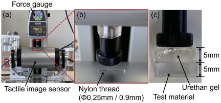
Fig. 7. Experimental setup for sensitivity verification. (a) A small nylon thread was pressed against the surface of the roller-type sensor while measuring the applied force with a force gauge. (b) Two nylon threads with different diameters (0.25 mm and 0.9 mm) were used. (c) A structure mimicking the object material and the surface of the other roller-type sensor was placed between the nylon thread and the force gauge probe. Experiments were conducted using the object materials with three different levels of hardness.
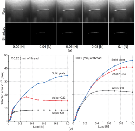
Fig. 8. Results of the sensitivity verification experiments. (a) Output images and their binarized versions for a 0.25-mm nylon thread under low forces (0.02–0.1 N). (b) Relationship between the applied force and the response intensity (number of detected pixels in the binarized image) for nylon threads with diameters of 0.25 mm and 0.9 mm.
3.2. Experimental Results
Figure 8 shows the experimental results. A nylon thread was pressed against the surface of the roller-type tactile sensor via a force gauge, and the load was varied from 0 to 1.0 N while acquiring output images from the tactile image sensor. Background subtraction and binarization were applied to the acquired contact images. The binarization threshold was determined from the valley position between the peaks corresponding to the background and the foreground (i.e., the response associated with the nylon thread) in the image histogram.
The upper part of Fig. 8 shows the output images obtained for loads ranging from 0.02 to 0.10 N in the case of the nylon thread with a diameter of 0.25 mm, which produced the smallest response among the tested threads, on the urethane gel C0 test material. As the load increases, the area of white pixels in the binary images increases. Even for foreign objects resting on an extremely soft material such as urethane gel with Asker C0 hardness, a sufficient response can be obtained by applying a load of 0.08 N or more.
The graph in the lower part of Fig. 8 shows the relationship between the applied load and the number of pixels detected through binarization (indicated in white). For each condition, the same experiment was performed three times, and the average values were used in the graph. Separate graphs are presented for nylon threads with diameters of 0.25 mm and 0.9 mm, which were used as foreign-object models. In each graph, the response increases as the load increases, but in some cases it saturates beyond a certain load. For the graph corresponding to the 0.25 mm nylon thread, when the food-mimicking materials were urethane gel C0 or urethane gel C23, the response saturated at approximately 0.2 N and 0.3 N, respectively, whereas the response continued to increase for the acrylic plate. The cause of this saturation is considered to be that, when the test material is softer than the nylon thread, the thread is pushed into the deformed material as the load increases, reducing the surface irregularities. In contrast, because the acrylic plate is as hard as the nylon thread, it does not deform even under increasing load, allowing the surface irregularities to be maintained, and thus the response continues to increase. In addition, the number of detected pixels is larger in the order of acrylic plate, urethane gel C23, and urethane gel C0. This indicates that the harder the inspected object is, the greater the sensor response becomes. Furthermore, the 0.9 mm nylon thread generates a larger overall response than the 0.25 mm thread, indicating that thicker foreign objects are easier to detect.
4. Inspection of Both Front and Back Surfaces of Food
We investigated the feasibility of applying the developed double-roller tactile image sensor to foreign object detection in actual food products. As the test specimen, we used raw shrimp, as shown in Fig. 9. Two types of shrimp were prepared: one with the shell completely removed and another with a portion of the shell intentionally left on one side, which served as the foreign object to be detected. The shrimp had a maximum thickness of approximately 13 mm, and the remaining shell portion measured approximately 9 mm in thickness. The shrimp were inserted from above into the gap between the two rollers for the experiments. Measurements were conducted for two roller gaps: 8.0 mm and 9.5 mm.
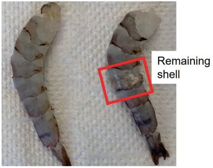
Fig. 9. Raw shrimp used in the experiment. The figure shows a shrimp from which the shell was completely removed (left) and a shrimp with part of the shell remaining on one side (indicated by the red square).
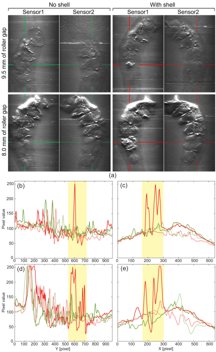
Fig. 10. Experimental results for raw shrimp. (a) Tactile images of both sides obtained from the shrimp without shell and the shrimp with shell. The distance between the two rollers was set to 9.5 mm and 8.0 mm. (b, c) Horizontal (\(X\)) and vertical (\(Y\)) profiles of the tactile images for the 9.5 mm roller spacing. Green indicates the profile obtained from the shrimp without shell, and red indicates the profile obtained from the shrimp with shell. (d, e) Horizontal (\(X\)) and vertical (\(Y\)) profiles of the tactile images for the 8.0 mm roller spacing. Green indicates the profile obtained from the shrimp without shell, and red indicates the profile obtained from the shrimp with shell. In each graph, the solid lines represent the output from Sensor 1, and the dashed lines represent the output from Sensor 2. The yellow areas correspond to the location of the shell.
Figure 10 shows the tactile images simultaneously acquired from the top and bottom sides of the shell-free and shell-attached shrimp using the double-roller tactile imaging sensor. Images obtained with roller gaps of 9.5 mm and 8.0 mm are presented in the upper and lower rows, respectively. The green and red lines in Fig. 10(a) indicate the positions where the pixel value profiles (Figs. 10(b)–(e)) were acquired. Regarding slippage between the roller and the shrimp in this experiment, there was almost no difference in the length of the object on the output image between the four different experiments, which indicates that no significant slippage occurred. For each image, the horizontal (\(X\)) and vertical (\(Y\)) intensity profiles corresponding to the region with the remaining shell are shown in the middle and bottom graphs. In each graph, the profiles for the shell-free and shell-remained shrimp are plotted in green and red, respectively. Figs. 10(b) and (d) are plots of pixel values along the \(Y\) coordinate at a specific \(X\) position indicated in Fig. 10(a), with a 10-pixel moving average in the \(Y\) direction applied to remove high frequency image noise. Similarly, Figs. 10(c) and (e) are plots of pixel values along the \(X\) coordinate at a specific \(Y\) position indicated in Fig. 10(a), with a 10-pixel wide moving average in the \(X\) direction. In Figs. 10(b), (c), and (e), only the red solid line (Sensor 1 for the shrimp with shell) shows a large response at the shell region. This means, for both roller-gap conditions, the images of the shrimp with shell exhibit regions of elevated intensity that do not appear in the shell-free images, indicating the potential for detecting the remaining shell. In particular, when the roller gap is 9.5 mm, the response at the shell region is significantly larger than at any portion of the shell-free shrimp, making it possible to easily detect as a foreign object.
However, when the roller gap is reduced to 8.0 mm, although the shell region still produces a strong response, the thicker portion of the shrimp (upper area of the tactile image) also produces a similarly large response (Fig. 10(d)). This occurs because the greater thickness of the shrimp increases the force with which the roller sensor is pressed against it. Conversely, the tail region (lower area of the tactile image), which is relatively thinner, experiences a weaker pressing force and therefore yields a smaller response. These results indicate that selecting an appropriate roller gap according to the thickness of the object enables reliable detection of foreign objects such as shrimp shells.
In actual image processing for this foreign object inspection, a uniform process is applied to the entire image to detect foreign objects. For example, the raw image obtained from the tactile sensor is binarized based on thresholding, followed by detection of connected components (blobs) and removal of minute regions based on their area, resulting in the detection of the remaining connected components as foreign objects. Introducing detection methods based on deep learning might also be effective. Developing detection algorithms tailored to specific foreign objects will be a challenge for each application.
5. Conclusion and Discussion
In this study, we developed a double-roller tactile image sensor that combines two roller-type sensors to simultaneously inspect both the top and bottom surfaces of an object. The sensor employs a reflective-membrane structure, enabling visualization of fine surface irregularities. The object is placed between the two roller sensors, and tactile images are continuously acquired while the rollers rotate. These images are then stitched together to generate a tactile image of the entire object surface. Sensitivity experiments demonstrated that a thin nylon thread with a diameter of 0.25 mm placed on a soft specimen with Asker C0 hardness could be detected when a pressing force of at least 0.1 N was applied. Furthermore, we evaluated the sensor’s response to remaining shell fragments on raw shrimp. By appropriately setting the gap between the two rollers, the shell fragments could be selectively detected.
On the other hand, in the current design, the positions of the two roller sensors are fixed, so to achieve the appropriate pressing force, the distance between the two rollers must be set appropriately depending on the thickness of the target object. For objects with a constant thickness, such as a printed circuit board, the appropriate roller distance can be selected in advance. However, if the thickness of the object changes, the pressing force applied by the rollers will vary depending on the location, which will affect the response amplitude. In the shrimp-shell detection experiment, not only the shell fragments, which are the intended foreign objects, but also the thicker portions of the shrimp produced similarly large responses. To address this issue, it is desirable to introduce a mechanism that maintains a constant pressing force between the two rollers regardless of object thickness. For example, a slider mechanism combined with a spring that generates a constant load may be used. Also, in the present configuration, only one of the rollers is driven by a motor, while the other roller rotates through frictional contact with the object. Although sufficient friction was available in the experiments conducted here, problems may arise when the object is slippery and the friction force is insufficient. Driving both rollers using gears or similar mechanisms would improve the robustness and versatility of the system. Furthermore, if a mechanism that can actively control the roller spacing is introduced, it may be possible to estimate mechanical properties such as the hardness of an object by continuously changing the roller spacing and analyzing tactile images at different contact forces. As another challenge, expanding the range of objects to be inspected is a practically important issue. While increasing the length of the rollers would be beneficial, it is necessary to consider methods for achieving a uniform contact pressure distribution across the width. It may also be necessary to increase the number of cameras to cover a wider contact area. In a proposed tactile image sensor integrated into a robot link, cameras are mounted at both ends of a cylinder to capture its interior, and this design could serve as a useful reference 25.
In future work, we will evaluate whether the inspection speed and actual detection performance satisfy the practical requirements of real product inspection.
- [1] T. Brosnan and D.-W. Sun, “Improving quality inspection of food products by computer vision–A review,” J. of Food Engineering, Vol.61, No.1, pp. 3-16, 2004. https://doi.org/10.1016/S0260-8774(03)00183-3
- [2] R. S. Dahiya, G. Metta, M. Valle, and G. Sandini, “Tactile sensing-from humans to humanoids,” IEEE Trans. on Robotics, Vol.26, No.1, pp. 1-20, 2010. https://doi.org/10.1109/TRO.2009.2033627
- [3] S. Luo, N. F. Lepora, W. Yuan, K. Althoefer, G. Cheng, and R. Dahiya, “Tactile robotics: An outlook,” IEEE Trans. on Robotics, 2025. https://doi.org/10.1109/TRO.2025.3608686
- [4] K. Sato, L. Canete, and T. Takahashi, “Development of a spray-coated tactile sensor – Prototype and modeling of 2D sensor on cylindrical surface –,” J. Robot. Mechatron., Vol.31, No.6, pp. 882-893, 2019. https://doi.org/10.20965/jrm.2019.p0882
- [5] K. Watatani, K. Terao, F. Shimokawa, and H. Takao, “A MEMS tactile sensor with fingerprint-like array of contactors for high resolution visualization of surface distribution of tactile information,” J. Robot. Mechatron., Vol.32, No.2, pp. 305-314, 2020. https://doi.org/10.20965/jrm.2020.p0305
- [6] Y. Tanaka, S. Shiraki, K. Katayama, K. Minamizawa, and D. Prattichizzo, “Bilaterally shared haptic perception for human-robot collaboration in grasping operation,” J. Robot. Mechatron., Vol.33, No.5, pp. 1104-1116, 2021. https://doi.org/10.20965/jrm.2021.p1104
- [7] H. Li, Y. Lin, C. Lu, M. Yang, E. Psomopoulou, and N. F. Lepora, “Classification of vision-based tactile sensors: A review,” IEEE Sensors J., Vol.25, No.19, pp. 35672-35686, 2025. https://doi.org/10.1109/JSEN.2025.3599236
- [8] S. Zhang et al., “Hardware technology of vision-based tactile sensor: A review,” IEEE Sensors J., Vol.22, No.22, pp. 21410-21427, 2022. https://doi.org/10.1109/JSEN.2022.3210210
- [9] S. Li et al., “When vision meets touch: A contemporary review for visuotactile sensors from the signal processing perspective,” IEEE J. of Selected Topics in Signal Processing, Vol.18, No.3, pp. 267-287, 2024. https://doi.org/10.1109/JSTSP.2024.3416841
- [10] K. Shimonomura and H. Nakashima, “A combined tactile and proximity sensing employing a compound-eye camera,” Proc. of IEEE SENSORS 2013, pp. 1464-1465, 2013. https://doi.org/10.1109/ICSENS.2013.6688497
- [11] K. Nozu and K. Shimonomura, “Robotic bolt insertion and tightening based on in-hand object localization and force sensing,” Proc. of 2018 IEEE/ASME Int. Conf. on Advanced Intelligent Mechatronics (AIM), pp. 310-315, 2018. https://doi.org/10.1109/AIM.2018.8452338
- [12] K. Shimonomura, “TacTile image sensors employing camera: A review,” Sensors, Vol.19, No.18, Article No.3933, 2019. https://doi.org/10.3390/s19183933
- [13] B. Ward-Cherrier, N. Pestell, L. Cramphorn, B. Winstone, M. Elena Giannaccini, J. Rossiter, and N. F. Lepora, “The TacTip family: Soft optical tactile sensors with 3D-printed biomimetic morphologies,” Soft Robotics, Vol.5, No.2, pp. 216-227, 2018. https://doi.org/10.1089/soro.2017.0052
- [14] C. Sferrazza and R. D’Andrea, “Sim-to-real for high-resolution optical tactile sensing: From images to three-dimensional contact force distributions,” Soft Robotics, Vol.9, No.5, pp. 926-937, 2022. https://doi.org/10.1089/soro.2020.0213
- [15] G. Zhang, Y. Du, H. Yu, and M. Y. Wang, “DelTact: A vision-based tactile sensor using a dense color pattern,” IEEE Robotics and Automation Letters, Vol.7, No.4, pp. 10778-10785, 2022. https://doi.org/10.1109/LRA.2022.3196141
- [16] W. Yuan, S. Dong, and E. H. Adelson, “GelSight: High-resolution robot tactile sensors for estimating geometry and force,” Sensors, Vol.17, No.12, Article No.2762, 2017. https://doi.org/10.3390/s17122762
- [17] M. Lambeta et al., “DIGIT: A novel design for a low-cost compact high-resolution tactile sensor with application to in-hand manipulation,” IEEE Robotics and Automation Letters, Vol.5, No.3, pp. 3838-3845, 2020. https://doi.org/10.1109/LRA.2020.2977257
- [18] K. Shimonomura, T. Chang, and T. Murata, “Detection of foreign bodies in soft foods employing tactile image sensor,” Frontiers in Robotics and AI, Vol.8, Article No.774080, 2021. https://doi.org/10.3389/frobt.2021.774080
- [19] G. Cao, J. Jiang, C. Lu, D. F. Gomes, and S. Luo, “Touchroller: A rolling optical tactile sensor for rapid assessment of textures for large surface areas,” Sensors, Vol.23, No.5, Article No.2661, 2023. https://doi.org/10.3390/s23052661
- [20] M. A. Mirzaee, H.-J. Huang, and W. Yuan, “GelBelt: A vision-based tactile sensor for continuous sensing of large surfaces,” IEEE Robotics and Automation Letters, Vol.10, No.2, pp. 2016-2023, 2025. https://doi.org/10.1109/LRA.2025.3527306
- [21] A. Yamaguchi and C. G. Atkeson, “Recent progress in tactile sensing and sensors for robotic manipulation: Can we turn tactile sensing into vision?,” Advanced Robotics, Vol.33, pp. 661-673, 2019. https://doi.org/10.1080/01691864.2019.1632222
- [22] H. Sun, K. J. Kuchenbecker, and G. Martius, “A soft thumb-sized vision-based sensor with accurate all-round force perception,” Nature Machine Intelligence, Vol.4, pp. 135-145, 2022. https://doi.org/10.1038/s42256-021-00439-3
- [23] S. Yuan et al., “Tactile-reactive roller grasper,” IEEE Trans. on Robotics, Vol.41, pp. 1938-1955, 2025. https://doi.org/10.1109/TRO.2025.3543324
- [24] W. K. Do, A. Kundan Dhawan, M. Kitzmann, and M. Kennedy, “DenseTact-Mini: An optical tactile sensor for grasping multi-scale objects from flat surfaces,” 2024 IEEE Int. Conf. on Robotics and Automation (ICRA), pp. 6928-6934, 2024. https://doi.org/10.1109/ICRA57147.2024.10610583
- [25] Q. K. Luu, D. Q. Nguyen, N. H. Nguyen, N. P. Dam, and V. A. Ho, “Vision-based proximity and tactile sensing for robot arms: Design, perception, and control,” IEEE Trans. on Robotics, Vol.41, pp. 5000-5019, 2025. https://doi.org/10.1109/TRO.2025.3593087
This article is published under a Creative Commons Attribution-NoDerivatives 4.0 Internationa License.