
Paper:
Mechanical Ghost Palpation (MGP): Application of Ghost Imaging for Tactile Sensing and Basic Validation
Koichiro Kanaya*1, Shunta Ide*1, Takahiro Asano*2, Kenichi Murakami*3
 , and Yuji Yamakawa*4
*1School of Engineering, The University of Tokyo
4-6-1 Komaba, Meguro-ku, Tokyo 153-8505, Japan
*2Institute of Industrial Science, The University of Tokyo
4-6-1 Komaba, Meguro-ku, Tokyo 153-8505, Japan
*3Research Institute for Science and Technology, Tokyo University of Science
6-3-1 Niijuku, Katsushika-ku, Tokyo 125-8585, Japan
*4Interfaculty Initiative in Information Studies, The University of Tokyo
4-6-1 Komaba, Meguro-ku, Tokyo 153-8505, Japan

To achieve global palpation efficiently and without the use of tactile sensors, this study proposes mechanical ghost palpation (MGP), which applies the concept of ghost imaging (GI) to palpation, and verifies its basic principle. However, unlike general GI, which uses light as a medium, the configuration of the pressing patterns in MGP, which involves mechanical contact, presents system-specific challenges: from the correlation between the pattern structure and pressing depth, to the replacement and mass production of the patterns. To overcome these issues, in this work, we proposed a pattern configuration method that imposes constraints on the number of contact points and the centroid of their positions, and further proposed a technique to virtually increase pattern diversity by using a rotation operation on two square patterns. In the experiment, we estimated the stiffness map of a silicone gel phantom containing an embedded inclusion within a 5×5 grid by performing a total of 8 times pressing operations (using two pressing patterns). The results confirmed that the inclusion’s location was included within the top three highest-stiffness positions in the MGP-estimated stiffness map. This achievement demonstrates the potential of MGP to efficiently perform global palpation independent of tactile sensors.
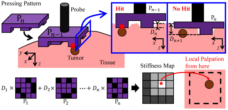
MGP: press patterns to locate tumor
1. Introduction
The tactile sense is an important sensory function to detect irregularities on a target object, especially in cases when visual inspection is difficult. It is effective, for instance, when detecting tumors or lumps beneath the skin, which is generally done by using the palm or multiple fingers to first search over a wide area, and then carrying out a local search using the finger tips 1. The global search conducted in the initial stage is important to improve the detection accuracy and efficiency of the local search. This kind of tactile exploration is used also for palpation prior to laparotomy, and has been established as a technique to detect cancer cells in the vicinity of the prostate or breast 2,3.
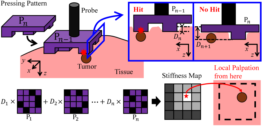
Fig. 1. Concept of MGP. The pressing pattern \(\rm{P}_\mathit{n}\) is pressed against the target object (tissue). The pressing depth \(D_n\) of the pressing pattern varies depending on whether it contacts the tumor. The final output of MGP, the stiffness map, which serves as a clue to the tumor’s location, is obtained by performing a correlation operation between this pattern \(\rm{P}_\mathit{n}\) and the depth \(D_n\). The correspondence with GI is as follows: pressing the pattern corresponds to the projection of the pattern by a projector, and measuring the pressing depth \(D_n\) corresponds to the measurement of light intensity by a single-pixel sensor.
In recent years, minimally invasive surgery, carried out through small skin incisions, is attracting attention because of its advantages such as the lower surgical risks or shorter recovery period 4,5,6. The forceps grippers used in minimally invasive surgery are not equipped with tactile sensors because of space limitations or issues of biocompatibility 4,7. The absence of tactile sensors makes it difficult to carry out palpations in the manner described above during surgery. To resolve this issue, tactile sensors geared toward minimally invasive surgery and sensor-less tactile estimation methods have been developed 8,9,10, and some studies have realized local palpation 11,12,13. Yet, most approaches to global exploration consist of discrete probing that requires repeated local palpations, and an efficient method has yet to be established.
In this study, therefore, we apply ghost imaging (GI), used in the image measurement field, to achieve an efficient global exploration without the use of a tactile sensor. GI consists of using a projector to irradiate patterned light onto an object and then reconstructing the image of the target from a correlation operation using the reflected light intensity measured by a single-pixel sensor and the pattern, which allows imaging under environments with low S/N ratios 14. Application examples have been reported such as underwater imaging 15 and remote imaging 16. The feature of GI, i.e., extracting information of the target object from noise, can be used for the purpose of palpation. The observation target of palpation consists of tumors or lumps, while the skin cover or biological tissues can be viewed as noise which hinders this observation. Because this situation is similar to that in imaging in environments where GI has been applied, we apply GI to palpation. We call the palpation method based on the application of the GI concept “mechanical ghost palpation” (MGP), which is proposed in this paper. The concept of MGP is shown in Fig. 1. A pattern with random projections and recessions (or convex and concave shapes) is attached to the end of a probe, which is pressed against the target. The depth to which the pattern is pressed is measured, and the correlation between the depth and the pattern is computed to estimate the stiffness distribution of the target surface.
Since there have been no studies concerning the application of GI to palpation, to the authors’ knowledge, our objective here is to verify the principles of MGP, propose a method for its concrete application, and demonstrate its validity. Furthermore, we identify the requirements necessary to extend optical GI to mechanical MGP, so as to contribute to improving the relevant hardware and software.
3. Mechanical Ghost Palpation (MGP)
Since there are no previous studies on MGP, in this paper we verify the possibility of conducting global palpation using MGP. In Section 3.1, we describe the problem setting involved in verifying MGP. In Section 3.2, we describe the concept of the proposed MGP by comparing it with conventional GI. In Section 3.3, we discuss the requirements of the pressing pattern when GI is extended to MGP and its fabrication method.
3.1. Problem Setting
MGP is a global palpation approach designed to narrow down the search area for subsequent local palpation. The inputs for MGP are the indentation depths of the respective pressing patterns, while the output is the estimated probability distribution of the inclusion’s location. Local palpation is then directed only to the grid cells with a high probability of containing an inclusion, thereby reducing the total number of palpation trials. Therefore, in this fundamental validation of MGP, we focus primarily on identifying the approximate location of the inclusion, rather than characterizing its shape, size, or depth. As shown in Fig. 2, the target object is a square silicone phantom divided into a \(5 \times 5\) grids. Since exhaustive local palpation alone would require a maximum of 25 trials to locate the inclusion, we define the criterion for success as achieving identification with a combined total of fewer than 25 trials (MGP plus local palpation). However, for the purpose of evaluating MGP’s performance, physical local palpation is not actually executed; instead, the total number of trials required to locate the inclusion is calculated virtually based on the MGP estimation results.
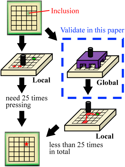
Fig. 2. Problem setting. The target object is a square silicone gel, and the measurement area is divided into \(5 \times 5\) grids. The objective is to identify the specific grid cell containing the inclusion while minimizing the total number of required palpation trials. Specifically, by utilizing MGP, we aim to complete this identification in fewer than 25 trials. Note that local palpation is not performed physically in this study; rather, it is conducted virtually.
3.2. Correspondence Between GI and MGP
In GI, a pattern with spatially random luminance is irradiated against the target from the projector. Since the reflectance and transmittance of the target vary along its surface, the reflected intensity measured by a single-pixel sensor differs with each pattern. By taking advantage of this phenomenon, the image of the target can be reconstructed by computing the correlation between the light intensity detected by the single-pixel sensor and the pattern 19,20. Denoting by \(I_n(x,y)\) the light intensity distribution of the projector’s \(n\)-th irradiation and by \(B_n\) the reflected light intensity measured by the single-pixel sensor, the correlation distribution of the deviation of light intensity, \(G(x,y)\), can be written as:
In MGP, the pressing pattern is mounted at the end of a probe, which presses it against the target according to preset reference values. When an inclusion is present in the target, the pressing depth varies depending on the arrangement of convex shapes on the pressing pattern. The pressing depth at this time is measured using the encoder housed in the probe. This operation is repeated \(n\)-th times by changing the pressing pattern attached to the probe. Denoting by \(\mathrm{P}_n(x,y)\) the shape of the pattern used in the \(n\)-th trial and by \(D_n\) the pressing depth measured using the encoder, the correlation distribution of the deviation of pressing depth, \(G_{\rm{p}}(x,y)\), can be expressed:
3.3. Extension of GI to MGP
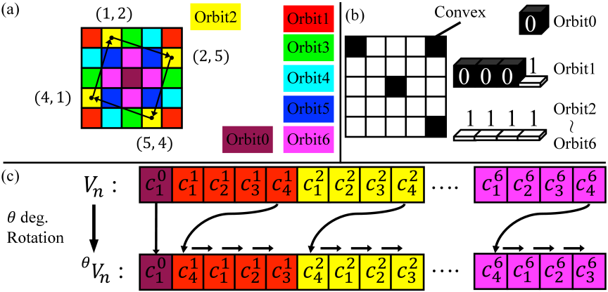
Fig. 3. The method for configuring the pressing pattern (fixing the number of convex shapes and introducing rotational asymmetry) and the use of vector representation to evaluate the pattern’s superiority. (a) Examples of convex-concave orbits when a \(5\times5\) divided square is rotated by 90° increments. (b) Example configurations of convex shapes focusing on the convex-concave orbits. (c) Vector representation method for pattern rotation.
MGP and GI have two major differences. The first is that the pressing depth depends not only on the relative positions of the inclusion and convex shapes of the pressing pattern but also on the structure of the pressing pattern. The second is that the pressing pattern entails a large fabrication cost and a manual replacement task.
With regard to the first issue, the pressure exerted by the pressing pattern on the target is lower when there are a greater number of convex shapes. As a result, the pressing depth is reduced. Thus, a correlation exists between the pattern’s structure besides the positions of the convex shapes and the pressing depth. It then becomes difficult to estimate the location of the inclusion on the MGP stiffness map when this correlation is large.
With regard to the second issue, GI readily allows the production of various patterns since they can be modified by software changes. Meanwhile, MGP requires fabrication of the patterns in advance, which must be manually replaced to switch patterns, so that there is a limit to the number of patterns available for measurement.
To address these issues, we rotate the probe end so that the number of patterns used for measurement can be reduced. By employing the same pattern for different trials, it is expected to lower the effect of the correlation between pattern structure and pressing depth.
3.3.1. Reducing the Correlation Between the Structure Other than Convex Shape Position and Pressing Depth
To reduce the correlation between the pressing pattern’s structure unrelated to the convex shapes’ positions and the pressing depth, we adopt the following requirements for the pressing pattern.
-
Performance requirement 1:
Using a fixed number of convex shapes.
-
Performance requirement 2:
Aligning the centroid of the convex shapes and the probe’s point of application.
Performance requirement 1 is based on the observation that the pressing depth is reduced when the pattern has a greater number of convex shapes, as noted earlier. Thus, the number of convex shapes on the pattern must be kept fixed. Performance requirement 2 is set because the probe applies force at the center of the pattern. When this requirement is met, the moments produced by the target’s reaction and the probe’s force are balanced. If this equilibrium is lost, the pattern will tilt and the pressing pattern will be pressed into the target to a greater extent. For this reason, it is desirable to align the probe’s point of application and the centroid of the convex shapes.
3.3.2. Reducing Correlation Between Pressing Patterns Used in MGP
It is known that, in GI, the quality of the reconstructed image improves as the correlation between the patterns irradiated in the \(n\)-th and \((n+1)\)-th trials lowers 20. In order to reduce the correlations between a pressing pattern and its rotated versions and among different pressing patterns, we additionally adopt the following requirements.
-
Performance requirement 3:
The pressing patterns must be rotationally asymmetric.
-
Coordination requirement 1:
The set must consist of pressing patterns with low correlations among them.
The patterns were first fabricated so that their arrangements satisfy performance requirements 1 and 3, then a selection was made to pick those that conform to performance requirements 2 and 3 and coordination requirement 1 to a high degree.
3.3.3. Fabrication and Selection of Pressing Patterns Based on Consideration of Rotation
We first describe the fabrication of pressing patterns that satisfy performance requirements 1 and 3, then discuss the method of assessment of performance requirement 3 and coordination requirement 1.
Arrangement of rotationally asymmetric patterns with fixed number of convex shapes (performance requirements 1 and 3)
Basic procedure: The pressing pattern’s cells are divided into subsets, where each subset corresponds to the pressing of specific points on the target.
The pressing patterns are fabricated in groups according to these subsets. We define the set of all possible positions that points on the surface of a given shape can occupy when subjected to a rotational operation as the convex-concave orbit (CC orbit). The CC orbits represent the subsets described above. For example, when a square sectioned into a \(5\times5\) matrix is incrementally rotated by 90°, as shown in Fig. 3(a), the 25 cells each describe one of seven CC orbits. Denoting by \((x, y)\) the coordinates of the \(x\)-th row and \(y\)-th column, CC orbit 2 is a subset consisting of four points, \((1, 2), (2, 5), (5, 4)\), and \((4, 1)\). CC orbit 0, at the center of the matrix, is the subset consisting only of \((3, 3)\). As this example shows, the number of cells that describe the CC orbit at the rotation center may be singularly different from those that describe other orbits. The singular CC orbit, which is denoted by CC orbit 0, is treated differently from the other CC orbits. We now introduce variables \(^{i}n_{\rm{conv.}}\) and \(a_j\) to the CC orbits, to formulize performance requirements 1 and 3. \(^{i}n_{\rm{conv.}}\): the number of convex shapes that describe CC orbit \(i\), \(a_j\): the number of CC orbits for which there are \(j\) convex shapes, where CC orbit 0 is excluded from \(a_j\). As shown in Fig. 3(b), for instance, the singular CC orbit 0 is included in the seven CC orbits, so that \(\sum_{j=0}^{4} a_{j} = 6\). Furthermore, CC orbit 0 consists of a single convex shape, CC orbit 1 of three convex shapes, while the other orbits have no convex shapes. Using the variables, this can be expressed as \(^0n_{\rm{conv.}} = 1\), \(^1n_{\rm{conv.}} = 3\), \(^2n_{\rm{conv.}} \sim \;^6n_{\rm{conv.}} = 0\).
For the pressing pattern to be rotationally asymmetric, at least one among \(a_1\), \(a_2\), or \(a_3\) must be nonzero. For a \(5 \times 5\) square, performance requirements 1 and 3 can be expressed as
Selection of patterns with high rotational asymmetry and low correlation: (a) Coordination requirement 1, (b) performance requirement 3
Basic procedure: The correlation between patterns is assessed by the inner product of vectors expressing arrangements of convex shapes on the pressing pattern. Rotation is expressed by shifting the vector components.
As shown in Fig. 3(c), the pressing pattern \(\rm{P}_\mathit{n}\) can be expressed by a vector \(\boldsymbol{V}_n \in \mathbb{R}^{1 \times 25}\), which consists of vector subspaces, each of which represents cells that describe a given CC orbit. Denoting by \(c^i_{k}\) the presence or absence of a convex shape at the \(k\)-th element of CC orbit \(i\), we can write
(a) Evaluation of and selection based on coordination requirement 1
The correlation \(R_{\rm{pattern}}\) between pressing patterns \(\rm{P}_\mathit{n}\) and \(\mathrm{P}_{n+1}\) can be written as
(b) Evaluation of and selection based on performance requirement 3
Next, in order to increase the number of pressing patterns based on rotation, we select patterns which display a low correlation between the original and rotated ones. When the figure possesses \(l\)-th order rotational symmetry, the minimum rotation angle is \({360}/{l}\) [°], so that rotation of the pattern can be expressed by shifting element \(c^i_{k}\) of each CC orbit \(i\) by one position. The vector \(^{\theta \rm{deg.}}\boldsymbol{V}_{n}\), obtained by rotating \(\boldsymbol{V}_n\) by \(\theta\) [°], is then expressed as:
The above method of producing pressing patterns using the CC orbits and assessing their correlation by employing lower-dimensional vectors is applicable to shapes other than squares, as shown in Fig. 4.
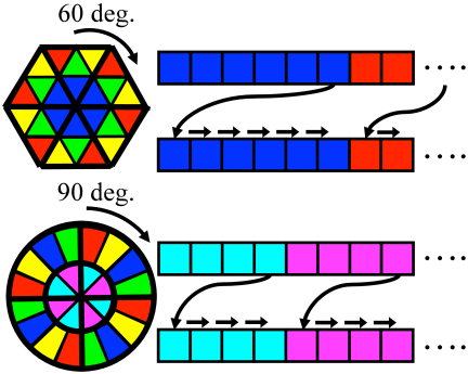
Fig. 4. The methods for configuring the pattern focusing on the convex-concave orbits and for representing pattern rotation using the vector representation are applicable to shapes other than a square, such as a hexagon or a circle.
4. Simulation Experiment
We carried out two simulations to determine the number of pressing patterns and those (\(N_{\rm{conv.}}\)) of the convex shapes on the pressing pattern. For simulation 1, keeping the number of convex shapes, \(N_{\rm{conv.}}\), constant, we generated 25 random patterns for each \(N_{\rm{conv.}}\). We then determined \(N_{\rm{conv.}}\) and the number of patterns from the detection accuracy of inclusions. In simulation 2, we checked to see whether the results of simulation 1 can be reproduced when the patterns were increased by rotation.
4.1. Simulation Conditions
Table 1. Simulation conditions.
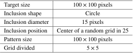
The simulation conditions of the target object and pressing pattern are presented in Table 1. The target consists of a square with the dimensions \(X= 100\) pixels wide and \(Y=100\) pixels long, which is sectioned into a \(5\times5\) array. A circular inclusion is placed at the center of a randomly selected cell. In the simulation, measurement of the pressing depth is idealized, where the depth takes the value 0 when a convex shape comes into contact with the inclusion and the value 1 when it does not come into contact with the inclusion. Furthermore, the deviation between the centroid of the convex shapes and the probe’s point of application is not taken into account. The detection accuracy of the inclusion is evaluated from the mean squared error (MSE) of its position in the target and the stiffness map, as follows:
4.2. Simulation Results
A pressing pattern with \(N_{\mathrm{conv.}}\) convex elements and a pressing pattern with \(25 - N_{\mathrm{conv.}}\) convex elements (i.e., \(N_{\mathrm{conv.}}\) concave elements) exhibit fundamentally identical detection performance, because the presence or absence of contact between the inclusion and the convex elements is simply reversed. For this reason, the evaluation range for \(N_{\mathrm{conv.}}\) was set from 1 to 13. The simulation results are shown in Fig. 5. It can be seen that the MSE of the red curve, representing \(N_{\mathrm{conv.}}=13\), the number of convex shapes, falls rapidly with the number of presses. Due to the characteristic of correlation operations, the stiffness map does not display information regarding the location of the inclusion when contact occurs with the inclusion at every press and when no contact occurs for every press. In other words, the detection accuracy suffers due to lack of information about the entire target when \(N_{\mathrm{conv.}}\) is low and there exists a bias on the position of the convex shape on the pressing pattern. In the case of \(N_{\mathrm{conv.}}=13\), when roughly one-half of the cells represent convex shapes, there is a 50% probability of contact at each press, which is why information is acquired efficiently. Regarding the number of palpation trials, the rate of decrease in the MSE diminishes after the eighth trial. We attribute this to the fact that setting \(N_{\mathrm{conv.}} = 13\) creates conditions similar to a binary search. However, because the pressing patterns are generated randomly in this simulation, more trials are required compared to the theoretical minimum of five trials expected in an ideal binary search. Therefore, in simulation 2, we employ two patterns which are varied by rotating them, each of which is pressed eight times.
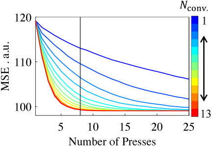
Fig. 5. Results of simulation 1. Relationship between the stiffness map and MSE of the object when varying the number of convex shapes (\(N_{\rm{conv.}}\); 1–13) in the pressing pattern. For each number of convex shapes, 25 random patterns were generated (pushing 25 times).
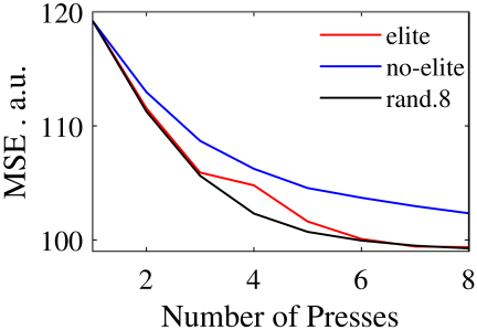
Fig. 6. Results of simulation 2. Comparison of stiffness map generation and MSE evaluation using two pressing patterns with a fixed number of convex shapes (\(N_{\rm{conv.}} = 13\)). Elite: Two patterns selected through pattern selection. No-elite: Two patterns generated randomly without selection. Rand.8: Eight random patterns without augmentation by rotation.
The results of simulation 2 are shown in Fig. 6. In this simulation, we randomly fabricated pressing patterns under the limitation that they must be rotationally asymmetric. In order to narrow down the selection of pressing patterns to satisfy performance requirement 3 and coordination requirement 1, we first generated 100 pairs of patterns, then selected from among them pairs of patterns that displayed the lowest correlations of Eqs. \(\eqref{eq:pattern_correlation}\) and \(\eqref{eq:rotation_correlation}\). In the simulation, the following three conditions were compared.
-
Elite: Two pressing patterns that were selected by the above process.
-
No-elite: Two pressing patterns that were not subjected to any selection process.
-
Rand.8: Eight patterns randomly selected and not increased by rotation.
In terms of the effect of increasing patterns by rotation, we found a significant difference between the final MSE values of non-elite and rand.8, indicating that simple rotation lowers the detection accuracy. Meanwhile, the rate of decline and final values of MSE of elite and rand.8 were about the same, which suggests that the effect of increasing patterns by simple rotation can be offset by evaluating the correlation and subjecting the patterns to a strict selection process.
5. Experiment Using Actual Devices
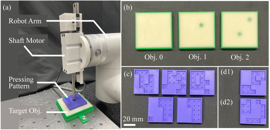
Fig. 7. Experiment setup. (a) Using a shaft motor as the probe to press the pressing pattern onto the target object. (b) Target objects used in the experiment. Obj.0: Object with no inclusion. Obj.1: Object with one inclusion. Obj.2: Object with two inclusions. (c) Pressing pattern where the centroid of the convex positions is different from the probe’s action point. (d) Pressing pattern where the centroid of the convex positions aligns with the probe’s action point.
Based on the simulation results, we conducted two experiments using two pressing patterns with \(N_{\rm{conv.}}=13\) (num. of convex shapes). The first result is described in Section 5.2, where we verify performance requirement 2, i.e., the need to align the convex-shape centroid and the probe’s point of application. The second result is presented in Section 5.3, where we examine the feasibility of using MGP for global palpation.
5.1. Experiment Method
The experiment setup is shown in Fig. 7(a). To press the pressing pattern using a probe, we employed a shaft motor (SL083, Nippon Pulse Motor Co.) mounted to a robot arm (FR5, FairINO). The pressing pattern, with the dimensions \(48\times 48\) mm, was fabricated using a 3D printer. The target consists of a \(70\times 70 \times 9\) mm silicone-gel block (stiffness 0, Exseal Co.), of which the central area was used as the search range for inclusions. The shaft motor was driven by PD control (\(K_{\rm{p}} = 0.736\) N/mm, \(K_{\rm{d}} = 0.400\) Ns/mm) to follow a fifth-order polynomial \(z_{\rm{ref}}\), to press the pressing pattern. Note that the boundary conditions for the fifth-order polynomial are \(z_{\mathrm{ref}}(0)=z_{\mathrm{ref}}(10~\mathrm{s})=1\) mm, and \(\dot{z}_{\mathrm{ref}}(0)=\dot{z}_{\mathrm{ref}}(10~\mathrm{s})=\ddot{z}_{\mathrm{ref}}(0)=\ddot{z}_{\mathrm{ref}}(10~\mathrm{s})=0\) mm/s.
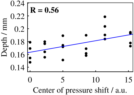
Fig. 8. Relationship between pressing depth and the shift between the center of gravity of the convex positions and the probe’s action point.
5.2. Correlation Between Pressing Depth and Deviation Between Convex-Shape Centroid and Point of Application
The probe’s point of application is fixed at the center of the pressing pattern. We measured the pressing depth using multiple patterns with different convex-shape centroids, thereby varying the deviation of the point of application and centroid. We used Obj.0, shown in Fig. 7(b), with no inclusions, as the target and the pressing patterns shown in Figs. 7(c) and (d1). For each pressing pattern with a different convex-shape centroid, we carried out four presses and measured the pressing depths, which are shown in Fig. 8. The correlation coefficient between the deviation and pressing depth was found to be \(0.56\), where the results displayed the tendency of increasing pressing depth with greater deviations. This finding suggests the need to limit the use of pressing patterns in MGP to those for which the deviation between the convex-shape centroid and probe point of application is small.
5.3. Verification Experiment of MGP
We conducted an experiment to verify the feasibility of using MGP for global palpation. As targets, we used two blocks which contained inclusions, as shown in Fig. 7(b). Obj.1 has a single inclusion while Obj.2 has two inclusions. The pressing patterns used are those shown in Figs. 7(d1) and (d2). These patterns were selected from those which were successful in locating the inclusion in simulation 2, described in Section 4.2, but in which the convex-shape centroid and probe application point are aligned.
In order to realize MGP, it is necessary for the pressing depth to vary depending on the number of inclusions which have come into contact with the pattern. Table 2 presents the results of the pressing depth of the patterns according to the number of inclusions (num. hits) that have come into contact with the pattern. It can be seen that the pressing depth decreases as the number of inclusions in contact with the convex shapes increases, indicating that the basic performance necessary for MGP is satisfied. The pressing depths of Table 2 are sufficiently above the measurement limit since the encoder’s resolution is 5 . Furthermore, in light of the experimental conditions described in Section 5.1, the influence of vibrations and deflection within the support system is considered to be negligible.
Table 2. Depth based on the number of inclusions contacted by the pattern.
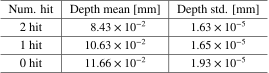
Table 3. Evaluation results of the MGP stiffness map. First hit: the number of local palpation attempts required to first detect the inclusion after starting local palpation. Max palpation: the maximum number of local palpation attempts required to detect the second inclusion after starting local palpation.
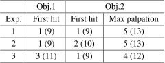
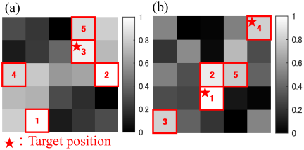
Fig. 9. Examples of the stiffness map in experiment 3. The color intensity indicates the palpation priority: whiter colors denote higher palpation priority, and blacker colors denote lower palpation priority. The true positions of the inclusions are indicated by red stars. (a) Results for Obj.1. (b) Results for Obj.2.
Next, we constructed a stiffness map from the results of using two pressing patterns rotated to increase patterns, so that they were pressed a total of eight times. This map can be viewed as the global palpation results using MGP, and indicates the priorities to carry out local palpations. The stiffness map based on MGP was evaluated based on the following two indices. First hit/trial \(=\) the number of local palpations necessary to locate an inclusion after local palpation has been initiated. Max palpation/trial \(=\) the maximum number of palpations necessary to palpate the second inclusion after local palpation has been initiated.
The results of three MGP trials against each target are presented in Table 3. The numbers given in the parentheses are the total number of palpations, which is the sum of the eight presses for MGP and the number of local palpations. The expectation values of the number of trials needed to palpate all inclusions using only local palpations to carry out a global search, without the use of the MGP stiffness map, are 13 for Obj.1 and approximately 17 for Obj.2. In view of the expectation values for global searches and the results of Table 3, we can expect that global palpations using MGP reduce the number of local palpations. Stiffness maps obtained in experiment 3 (Exp.3) of Table 3 are shown in Fig. 9. The cells given higher priorities for local palpation are displayed in brighter shades of white while those with lower priorities are displayed with darker shades of gray approaching black. It can be seen that the cells with higher palpation priorities are not necessarily closer to the inclusions. This is because the stiffness maps display a degree of rotational symmetry due to the increased patterns based on rotation. A map displaying perfect rotational symmetry can be viewed as showing the priorities of the CC orbits. In such cases, we feel that the tradeoff curve between the number of palpations and search accuracy can be shifted to a higher performance range by carrying out MGP searches in half regions of the target or varying the number of convex shapes, before conducting local palpations.
6. Conclusion
The instruments used in minimally invasive surgery are not equipped with tactile sensors because of space limitations or the need for robustness to withstand sterilization procedures. Sensors and methods to estimate tactile sense have been developed to make palpations possible in this kind of environment. Yet, most studies focus only on local palpations, so that no technology has yet been established that achieves both efficiency and accuracy in global palpations. In this study, therefore, we applied the concept of GI employed in the field of image measurement to palpation, and proposed MGP. From experiments using actual devices, we confirmed the possibility of carrying out sensorless global palpation using MGP. Furthermore, to apply GI to MGP, we pointed out the necessity to 1) show a clear correlation between the positions of convex shapes on the pressing pattern and the inclusions, and 2) reduce the number of pressing patterns. To achieve item 2), we adopted the approach of rotating the pressing patterns to increase their variety, and to satisfy item 1), identified the importance of three performance requirements and one coordination requirement. In the future, it will be necessary to reduce the size of the pressing patterns and develop folding/unfolding mechanisms aimed at their application to minimally invasive surgery. The above two findings should be relevant for the implementation of MGP. Furthermore, to enable the detection of inclusions within curved objects or at greater depths, we believe it is necessary to pursue simultaneous improvements in both hardware and software.
- [1] J. Konstantinova, A. Jiang, K. Althoefer, P. Dasgupta, and T. Nanayakkara, “Implementation of Tactile Sensing for Palpation in Robot-Assisted Minimally Invasive Surgery: A Review,” IEEE Sensors J., Vol.14, Issue 8, pp. 2490-2501, 2014. https://doi.org/10.1109/JSEN.2014.2325794
- [2] N. Wang, G. J. Gerling, R. M. Childress, and M. L. Martin, “Quantifying Palpation Techniques in Relation to Performance in a Clinical Prostate Exam,” IEEE Trans. on Information Technology in Biomedicine, Vol.14, Issue 4, pp. 1088-1097, 2010. https://doi.org/10.1109/TITB.2010.2041064
- [3] K. J. Saunders, C. A. Pilgrim, and H. S. Pennypacker, “Increased proficiency of search in breast self-examination,” Cancer, Vol.58, Issue 11, pp. 2531-2537, 1986. https://doi.org/10.1002/1097-0142(19861201)58:11<2531::AID-CNCR2820581128>3.0.CO;2-J
- [4] W. Wang, J. Wang, Y. Luo, X. Wang, and H. Song, “A Survey on Force Sensing Techniques in Robot-Assisted Minimally Invasive Surgery,” IEEE Trans. on Haptics, Vol.16, Issue 4, pp. 702-718, 2023. https://doi.org/10.1109/TOH.2023.3329172
- [5] P. S. Zarrin, A. Escoto, R. Xu, R. V. Patel, M. D. Naish, and A. L. Trejos, “Development of a 2-DOF Sensorized Surgical Grasper for Grasping and Axial Force Measurements,” IEEE Sensors J., Vol.18, Issue 7, pp. 2816-2826, 2018. https://doi.org/10.1109/JSEN.2018.2805327
- [6] A. M. Okamura, “Haptic feedback in robot-assisted minimally invasive surgery,” Current Opinion in Urology, Vol.19, No.1, pp. 102-107, 2009. https://doi.org/10.1097/MOU.0b013e32831a478c
- [7] A. L. Trejos, A. Escoto, D. Hughes, M. D. Naish, and R. V. Patel, “A sterilizable force-sensing instrument for laparoscopic surgery,” 5th IEEE RAS/EMBS Int. Conf. on Biomedical Robotics and Biomechatronics, pp. 157-162, 2014. https://doi.org/10.1109/BIOROB.2014.6913769
- [8] Z. Chua, A. M. Jarc, and A. M. Okamura, “Toward Force Estimation in Robot-Assisted Surgery Using Deep Learning with Vision and Robot State,” 2021 IEEE Int. Conf. on Robotics and Automation (ICRA), pp. 12335-12341, 2021. https://doi.org/10.1109/ICRA48506.2021.9560945
- [9] X. Wang, G. K. Ananthasuresh, and J. P. Ostrowski, “Vision-based sensing of forces in elastic objects,” Sensors and Actuators A: Physical, Vol.94, Issue 3, pp. 142-156, 2001. https://doi.org/10.1016/S0924-4247(01)00705-1
- [10] R. Xue, Z. Du, Z. Yan, and B. Ren, “An estimation method of grasping force for laparoscope surgical robot based on the model of a cable-pulley system,” Mechanism and Machine Theory, Vol.134, pp. 440-454, 2019. https://doi.org/10.1016/j.mechmachtheory.2018.12.032
- [11] A. Saracino, A. Deguet, F. Staderini, M. N. Boushaki, F. Cianchi, A. Menciassi, and E. Sinibaldi, “Haptic feedback in the da Vinci Research Kit (dVRK): A user study based on grasping, palpation, and incision tasks,” The Int. J. of Medical Robotics and Computer Assisted Surgery, Vol.15, Issue 4, Article No.e1999, 2019. https://doi.org/10.1002/rcs.1999
- [12] K. Li, B. Pan, J. Zhan, W. Gao, Y. Fu, and S. Wang, “Design and performance evaluation of a 3-axis force sensor for MIS palpation,” Sensor Review, Vol.35, Issue 2, pp. 219-228, 2015. https://doi.org/10.1108/SR-04-2014-632
- [13] Z. Tang, S. Wang, M. Li, and C. Shi, “Development of a Distal Tri-Axial Force Sensor for Minimally Invasive Surgical Palpation,” IEEE Trans. on Medical Robotics and Bionics, Vol.4, Issue 1, pp. 145-155, 2022. https://doi.org/10.1109/TMRB.2022.3142361
- [14] Y. Yan and J. Pan, “Fast Localization and Segmentation of Tissue Abnormalities by Autonomous Robotic Palpation,” IEEE Robotics and Automation Letters, Vol.6, Issue 2, pp. 1707-1714, 2021. https://doi.org/10.1109/LRA.2021.3058870
- [15] K. A. Nichols and A. M. Okamura, “Methods to Segment Hard Inclusions in Soft Tissue During Autonomous Robotic Palpation,” IEEE Trans. on Robotics, Vol.31, Issue 2, pp. 344-354, 2015. https://doi.org/10.1109/TRO.2015.2402531
- [16] H. Liu, D. P. Noonan, B. J. Challacombe, P. Dasgupta, L. D. Seneviratne, and K. Althoefer, “Rolling Mechanical Imaging for Tissue Abnormality Localization During Minimally Invasive Surgery,” IEEE Trans. on Biomedical Engineering, Vol.57, Issue 2, pp. 404-414, 2010. https://doi.org/10.1109/TBME.2009.2032164
- [17] Y. Tian, H. Ge, X.-J. Zhang, X.-Y. Xu, M.-H. Lu, Y. Jing, and Y.-F. Chen, “Acoustic Ghost Imaging in the Time Domain,” Physical Review Applied, Vol.13, No.6, Article No.064044, 2020. https://doi.org/10.1103/PhysRevApplied.13.064044
- [18] E. Rotunno, S. Gargiulo, G. M. Vanacore, C. Mechel, A. H. Tavabi, R. E. Dunin-Borkowski, F. Carbone, I. Madan, S. Frabboni, T. Guner, E. Karimi, I. Kaminer, and V. Grillo, “One-Dimensional “Ghost Imaging” in Electron Microscopy of Inelastically Scattered Electrons,” ACS Photonics, Vol.10, Issue 6, pp. 1708-1715, 2023. https://doi.org/10.1021/acsphotonics.2c01925
- [19] J. H. Shapiro, “Computational ghost imaging,” Physical Review A: Atomic, Molecular, and Optical Physics, Vol.78, No.6, Article No.061802, 2008. https://doi.org/10.1103/PhysRevA.78.061802
- [20] Y. Bromberg, O. Katz, and Y. Silberberg, “Ghost imaging with a single detector,” Physical Review A: Atomic, Molecular, and Optical Physics, Vol.79, No.5, Article No.053840, 2009. https://doi.org/10.1103/PhysRevA.79.053840
This article is published under a Creative Commons Attribution-NoDerivatives 4.0 Internationa License.