
Paper:
Development and Application of Wide-Range Precise Proximity Sensor
Shun Hasegawa*
 , Ayaha Nagata**
, Aoi Nakane*
, Masahiro Matsumura***, and Kei Okada*
, Ayaha Nagata**
, Aoi Nakane*
, Masahiro Matsumura***, and Kei Okada*
*Graduate School of Information Science and Technology, The University of Tokyo
7-3-1 Hongo, Bunkyo-ku, Tokyo 113-8656, Japan
**Graduate School of Interdisciplinary Information Studies, The University of Tokyo
7-3-1 Hongo, Bunkyo-ku, Tokyo 113-8656, Japan
***Kubota Global Institute of Technology, Kubota Corporation
1-11 Takumi-cho, Sakai-ku, Sakai, Osaka 590-0908, Japan

In this study, we defined a proximity sensor based on the fusion of an optical reflection intensity sensor and optical time-of-flight (ToF) sensor as a wide-range precise proximity sensor (WrPPS). This sensor can detect objects over a wide range, has low dependence on the physical properties of the detected object, and can be configured in a compact form. To allow the broad application of this sensor, we propose a WrPPS Single Board that packages the minimal configuration of this sensor onto a compact printed circuit board, allowing applications wherever this board can be mounted. Furthermore, to improve the accessibility of this board and allow easy application by anyone, we sell the board at a low price and release the fusion software for the intensity and ToF sensors as open-source software. The distance measurement accuracy of this sensor was quantitatively evaluated through experiments involving variations in the reflective properties, shape, and pose of the measurement target. To demonstrate the wide applicability of this sensor, we present examples of its applications, including grasping of compliant objects, tactile sensing in a stuffed robot, slip detection during walking, and agricultural plant sensing.
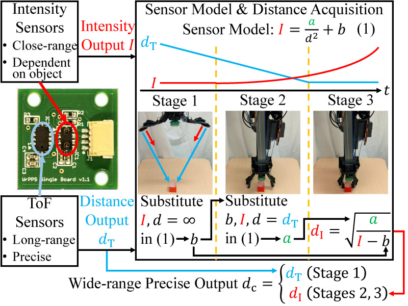
Principle of the WrPPS
1. Introduction
Proximity sensors have been used in robotics research for many years. Detection principles for proximity sensing include optical reflection intensity sensing 1,2,3,4,5, capacitive sensing 6, optical time-of-flight (ToF) sensing 7, ultrasound sensing 8, sensing of acoustic changes accompanying object approach 9, optical break-beam sensing 10, optical triangulation sensing 11, radar sensing 12, visual sensing 13, optical sensing using multiple modulated light sources 14, and inductive sensing; however, each of these has drawbacks such as limitations in detection range, strong dependence on the physical properties of the detected object, and large sensor size. Therefore, methods that combine multiple principles to compensate for the shortcomings of each principle 15,16,17,18,19,20 have been proposed.
Among these, the fusion of an optical reflection intensity sensor and an optical ToF sensor, which originated from our proposal 19,20, can create a sensor system that mitigates all three shortcomings. First, regarding the detection range, a wide range can be detected by combining the optical reflection intensity sensor, which can detect a close range but has difficulty simultaneously detecting a long range, with the optical ToF sensor, which can measure a long range but cannot precisely measure a close range. Second, regarding dependence on the physical properties of the detected object, because the optical reflection intensity sensor responsible for close-range detection strongly depends on the reflectance of the detected object, simply combining the two types of sensors does not eliminate the dependence on physical properties at close range. Therefore, when the detected object is within the overlapping detection range of the two types of sensors, the object-dependent parameter included in the model, which converts the intensity value of the optical reflection intensity sensor into the distance value to the object, is calculated using both the intensity value of the optical reflection intensity sensor and the distance value of the optical ToF sensor. Using this parameter, it becomes possible to generate a precise distance value with low dependence on the physical properties from the optical reflection intensity sensor, even when the detected object approaches a close range. Finally, regarding the sensor size, because both the optical reflection intensity and optical ToF sensors are compact, a sensor system combining them can also be mounted in narrow spaces, such as robot hands.
In this study, we define the sensor configured by the above fusion principle as a wide-range precise proximity sensor (WrPPS) and introduce the development of packaged sensor hardware and software as an implementation to allow the broad application of this principle, in contrast to our previous study 19, which was specialized for a specific robot hand. This hardware package is compact and can be mounted in many locations, allowing diverse applications. Furthermore, because it is commercially available at a low price and highly accessible, anyone can easily apply it. The software package is implemented in ROS, which is widely used in robot development, and is released as open-source software, also allowing easy application by anyone. This high applicability is expected to result in long-term sales, mass production benefits, and timely and appropriate updates. In addition, this study analyzes the performance of WrPPS in more detail than in our previous study 19. We quantitatively evaluated the distance measurement accuracy over a broader range, including cases targeting objects with specular reflectance, curved surface geometry, and tilt relative to the sensor. Finally, to demonstrate the broad applicability of this principle, we present application examples, including grasping of compliant objects, tactile sensing in a stuffed robot, slip detection during walking, and agricultural plant sensing.
2. Principle of WrPPS
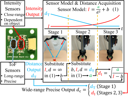
Fig. 1. Principle of the WrPPS.
This section describes the details of the detection principle of the WrPPS (Fig. 1). The details of this section can be found in our previous letter paper 19. However, to allow easy application by anyone, we explicitly introduce a precise output at any distance.
2.1. Model of Optical Reflection Intensity Sensor
We assumed the following model for an optical reflection intensity sensor on the basis of the inverse-square law of light:
2.2. Online Model Acquisition and Distance Measurement
Figure 1 illustrates the three stages of our sensing. First, we acquired the offset parameter \(b\) as the intensity output \(I\) when the object was too far for the intensity sensor to sense (Stage 1). Here, when the sensor is embedded in transparent rubber, as in our previous study 19, the intensity of the reflected light from bubbles inside the rubber and the rubber surface is included in \(b\). Therefore, it is necessary to use \(I\) while the sensor is emitting light. Subsequently, we acquired the object-dependent parameter \(a\) when the object was sensed by both the intensity and optical ToF sensors (Stage 2). This was conducted by substituting the ToF sensor output \(d_{\rm T}\) [mm] for \(d\) in Eq. \(\eqref{eq:eqnU003Ai-d-eq}\). Finally, we used \(b\) and \(a\) to convert \(I\) to \(d\) when the object was too close for the ToF sensor to detect precisely (Stage 3).
In Stages 2 and 3, the latest \(a\) and Eq. \(\eqref{eq:eqnU003Ai-d-eq}\) are used to calculate the precise distance value \(d_{\rm I}\) [mm] from the intensity output. The equation is explicitly written as follows:
3. Packaging WrPPS
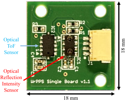
Fig. 2. WrPPS Single Board. This is an implementation that packages WrPPS onto a single PCB, allowing its broad application.
This section describes the WrPPS Single Board (Fig. 2), which packages WrPPS onto a single printed circuit board as an implementation to allow the broad application of the WrPPS.
3.1. Compact Package for High Versatility
In our previous study 19, WrPPS was constructed on the premise of being built into a specific robot hand, resulting in an implementation specialized for that hand. However, in the WrPPS Single Board, by consolidating the minimal configuration of WrPPS (i.e., a combination of one intensity sensor and one ToF sensor) onto a single board, it can be applied wherever this board can be mounted. By minimizing the configuration, a compact board size of \(18~\rm{mm}\times18~\rm{mm}\) was achieved, which is almost equivalent in size to a sensor designed to be mounted on robot fingertips a (\(16~\rm{mm}\times18~\rm{mm}\)), providing nearly equivalent mounting possibilities. In addition, three holes with a diameter of 2.2 mm were created to allow secure mounting. The sensors used were, as in our previous study 19, VCNL4040 (VCNL4040M3OE, Vishay Semiconductors) as the intensity sensor and VL53L0X (STMicroelectronics) as the ToF sensor, and their compact size greatly contributed to the miniaturization of the board.
3.2. Low-Cost Yet Highly Functional Package for High Accessibility
To allow the easy application of the WrPPS Single Board by anyone, we considered it necessary to improve the accessibility of the WrPPS Single Board and began selling the board through the Tokyo Open Source Robotics Kyokai Association b. Here, because of the low cost of the component parts, including the sensor elements, and because the assembly was completed through standard PCB assembly, keeping the assembly costs low, the board price was maintained at 7,700 yen, including tax. Comparing this price with other commercially available proximity sensors, it is slightly more expensive than sensors that detect proximity using only an intensity sensor a,c at $39.95 (approximately 5,993 yen at 150 yen per dollar) but far less expensive than a sensor based on the high-speed, high-precision proximity-sensing principle d at 242,000 yen, making it highly accessible.
Although the former sensors are less expensive, the drawbacks of narrow detection range and strong dependence on the physical properties of the detected object remain because they use only an intensity sensor for proximity sensing, making the WrPPS Single Board meaningful even at a slightly higher price. However, the latest one in the former sensors c also includes a pressure sensor, giving it the advantage of being able to readily detect contact pressure. In the future, we aim to introduce a transparent rubber cover as an option for the WrPPS Single Board and implement contact pressure detection using a principle based on measuring rubber deformation 2. In addition, the former sensors improved the usability by adopting a standardized communication connector e, and the WrPPS Single Board also adopts the same connector.
Although the latter sensor is very expensive, it excels in detection speed and accuracy compared with the WrPPS Single Board. However, the WrPPS Single Board is inexpensive, compact, and capable of long-range detection, making it particularly suitable for applications that require the placement of many sensors on robot surfaces or detection over a wide range.
3.3. ROS-Based Open-Source Software Package for High Adoptability
To improve the accessibility of the WrPPS Single Board from a software perspective, we packaged the software that performed the fusion of the intensity and ToF sensors and released it as open-source software f. This software is implemented in ROS, the de facto standard for distributed communication systems within robots, and can consistently handle sensor value acquisition using Arduino, the fusion of the intensity and ToF sensors, and the distribution of distance information. Users can begin the sensor initialization and ROS topic distribution by simply executing the following command:
    roslaunch wrpps_ros \
    wrpps_single_board.launch
This software provides the intensity sensor value \(I\), ToF sensor value \(d_{\rm T}\), distance value \(d_{\rm I}\) derived from the intensity sensor value, and distance value \(d_{\rm c}\) that integrates the ToF sensor value and distance value derived from the intensity sensor value as individual ROS topics. The final output \(d_{\rm c}\) is distributed as a sensor_msgs/Range type, which is the standard ROS distance sensor output format. This output can be obtained as follows:
    $ rostopic echo \
    > /wrpps_single_board\
    > /intensity_model_acquisition\
    > /output/range_combined
    header:
    frame_id: ''wrpps_single_board\
    _intensity_frame''
    field_of_view: 0.44
    min_range: 0.0
    max_range: 2.0
    range: 0.312
Thus, the WrPPS Single Board can be easily integrated into existing ROS-based robot systems and has high adoptability from a software perspective.
4. Evaluation of WrPPS
To quantitatively evaluate the performance of the WrPPS, we conducted distance measurement experiments using the WrPPS Single Board described in the previous section. The objects used as the measurement targets are shown in Fig. 3. First, from the 12 colors of paper used in our previous study 19, we selected three representative types: pink, green, and black. These correspond to the highest, intermediate, and lowest values from the intensity sensor, respectively. Subsequently, as an object possessing specular reflectance as well as diffuse reflectance, a plate made of A5052 (aluminum alloy) was used as the measurement target. Finally, as an object with a curved surface, a sphere made of white polylactic acid (PLA) was used as the measurement target. The diameter of the sphere was 80 mm, and it was cut in half to allow stable placement on a flat desk.
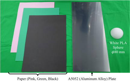
Fig. 3. Objects used as the measurement targets in the distance measurement experiments. Five types were used: pink paper, green paper, black paper, a plate made of A5052 (aluminum alloy), and a white polylactic acid (PLA) sphere (diameter 80 mm).
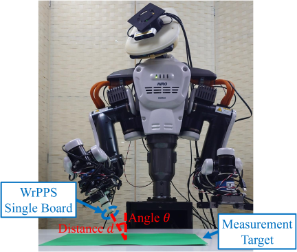
Fig. 4. Setup of the distance measurement experiments. The robot positioned the WrPPS Single Board in its end effector at distance \(d\) and angle \(\theta\) from the measurement target.
In the experiments, with the measurement target placed in front of a robot whose end effector contains the WrPPS Single Board, the robot moved its arm to position the sensor board at distance \(d\) and angle \(\theta\) from the measurement target, and the output of the sensor board was recorded. This procedure was repeated while varying \(d\) and \(\theta\). The setup is shown in Fig. 4. The robot used was HIRO-NX, a research-specification version of the dual-arm robot NEXTAGE g, with 6-axis force sensors (IFS-50M31A25-I25, Nitta) added to its end effectors. Position repeatability was 30 . The force sensor was used to determine the position of the target surface. Immediately after replacing the measurement target, the end effector was brought close to the measurement target while maintaining \(\theta=0°\), and contact was determined when the difference from the initial value of the vertically upward force measured by the force sensor exceeded 0.3 N. The position of the end effector surface at that time was recorded as the position of the target surface.
Experiments were conducted under indoor lighting conditions. According to the application note of the intensity sensor h, the emitter of the intensity sensor emits the pulsed light, which is measured by looking for the pulsed light at the proximity frequency used by the emitter. Therefore, it is insensitive to ambient light. On the other hand, according to the datasheet of the ToF sensor i, the standard deviation of the distance measurement by the ToF sensor when performed outdoors was up to twice that when performed indoors. From the above, for WrPPS, which uses both the intensity and ToF sensors, it is considered that the standard deviation could be up to twice when the lighting conditions change from indoor conditions.
4.1. Distance Measurement on Parallel Objects
First, distance measurement experiments were conducted with the sensor board parallel to the measurement target (\(\theta=0°\)). After acquiring \(I\) (intensity sensor output) at a distance \(d=280~\rm{mm}\) from the measurement target as \(b\) (offset parameter), \(d\) was decreased to \(80~\rm{mm}\rightarrow70~\rm{mm}\rightarrow60~\rm{mm}\rightarrow50~\rm{mm}\rightarrow40~\rm{mm}\rightarrow30~\rm{mm}\rightarrow20~\rm{mm}\rightarrow10~\rm{mm}\rightarrow5~\rm{mm}\rightarrow3~\rm{mm}\rightarrow1.95~\rm{mm}\), and 10 output values were recorded at each distance. The minimum distance was 1.95 mm because the connector of the sensor board was 1.95 mm higher than the sensor, causing the connector to contact the target before the sensor. By repeating this procedure of decreasing \(d\) from 80 mm 10 times, 100 (\(10\times10\)) output values were obtained for each distance.
The distance measurement results are shown in Figs. 5–9. For all measurement targets, when the distance was 10 mm or less, the performance of our sensor output \(d_{\rm c}\) exceeded that of the ToF sensor output \(d_{\rm T}\). Fig. 10 describes the intensity sensor output with the offset (\(I-b\)) obtained in this experiment. The intensity value for the pink paper was approximately 10 times as large as the value for the black paper. This difference was too big such that we had difficulty in using these values in the same manner (e.g., using the same threshold for touch detection). On the contrary, our sensor generated similar \(d_{\rm c}\) for the pink and black papers, showing that \(d_{\rm c}\) outperformed the intensity sensor output. For the white PLA sphere, the error of \(d_{\rm c}\) was larger than that for the paper; however, it was still considered small, given that the intensity value was approximately 7 times that for the black paper.
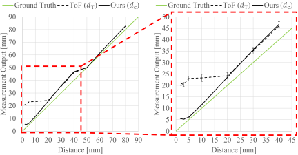
Fig. 5. Distance measurement results on the pink paper. The solid black line shows the distance output of our sensor (\(d_{\rm c}\)). The broken black line shows the ToF sensor output (\(d_{\rm T}\)). These lines were created with linear interpolation between the means of 100 measurements. The green line shows the ground-truth values (ideal for the sensors). The right graph is an enlarged view of the left graph. Each error bar in the right graph represents one standard deviation of 100 measurements. At a distance \(\leq10~\rm{mm}\), the line of \(d_{\rm c}\) is closer to the ground-truth line than \(d_{\rm T}\) and the error bar of \(d_{\rm c}\) is very small.
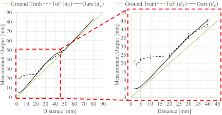
Fig. 6. Distance measurement results on the green paper. The format is the same as Fig. 5. The results were almost the same as Fig. 5.
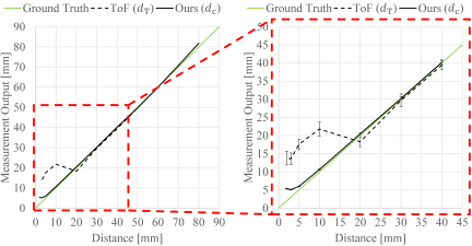
Fig. 7. Distance measurement results on the black paper. The format is the same as Fig. 5. At a distance \(\leq10~\rm{mm}\), the line of \(d_{\rm c}\) is closer to the ground-truth line than \(d_{\rm T}\) and the error bar of \(d_{\rm c}\) is very small.
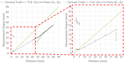
Fig. 8. Distance measurement results on the A5052 plate. The format is nearly the same as Fig. 5, but points where \(d_{\rm T}\) and \(d_{\rm c}\) became erroneous values (NaN) (\(d=10~\rm{mm}, 20~\rm{mm}, 30~\rm{mm}\)) are not plotted. Because \(d_{\rm I}\) was not erroneous even at these distances, this output is also shown by the dotted black line. Combination of \(d_{\rm c}\) and \(d_{\rm I}\) outperformed \(d_{\rm T}\) at a distance \(\leq50~\rm{mm}\).
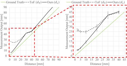
Fig. 9. Distance measurement results on the white PLA sphere. The format is the same as Fig. 5. At a distance \(\leq20~\rm{mm}\), the line of \(d_{\rm c}\) is closer to the ground-truth line than \(d_{\rm T}\).
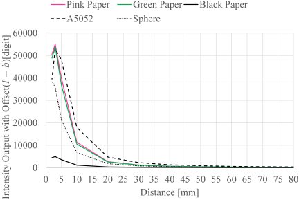
Fig. 10. Intensity sensor output with offset (\(I-b\)) in the distance measurement on the parallel objects. The output for pink was approximately 10 times as large as the output for black. Thus, we had difficulty in using them in the same manner (e.g., using the same threshold for touch detection).
For the A5052 plate, \(d_{\rm T}\) sometimes became an erroneous value (NaN) when attempting to measure at close range. This is likely because the strong specular reflectance of the object caused measurement errors in the ToF sensor. Typically, ToF-sensor measurement errors occur when the measurement target is extremely far from the sensor. Therefore, the current software treats these errors as indications that the measurement target is far away, and following Eq. \(\eqref{eq:eqnU003Acalc-d-c}\), \(d_{\rm c}\) was set to an erroneous value when \(d_{\rm T}\) was an erroneous value. On the other hand, at this time, the distance value \(d_{\rm I}\) converted from the intensity sensor value was normal. If \(d_{\rm I}\) had been output as \(d_{\rm c}\) at this time, although the distance error would have been large, a monotonically decreasing \(d_{\rm c}\) corresponding to a decrease in distance would have been obtained. Therefore, it is necessary to analyze objects with specular reflectance in more detail and improve the switching algorithm between \(d_{\rm T}\) and \(d_{\rm I}\) in the calculation of \(d_{\rm c}\). For the other measurement targets, \(d_{\rm T}\) sometimes had a smaller distance error than \(d_{\rm c}\) at relatively long distances (e.g., \(d=40~\rm{mm}\) in Fig. 6) because the value of \(d_{\rm I}\) rather than \(d_{\rm T}\) was output as \(d_{\rm c}\). Algorithm improvements to address this problem are also required. In addition, for all the measurement targets, \(d_{\rm c}\) decreased less steeply or even increased when \(d\) was reduced to 3 mm or less. This is because, as shown in Fig. 10, the intensity value increased less steeply or even decreased. Therefore, countermeasures such as attaching a cover to the sensor board to limit the approach of objects are required.
4.2. Distance Measurement on Tilted Objects
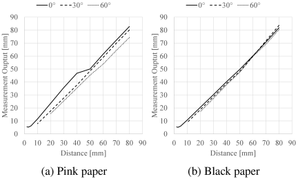
Fig. 11. Distance measurement results when tilting the sensor relative to the pink and black papers. The lines were created with linear interpolation of the mean of 100 measurements of \(d_{\rm c}\) at each distance. The broken line shows the results for \(\theta=30°\). The dotted line shows the results for \(\theta=60°\). For reference, the results for \(\theta=0°\) described above are also shown as a solid line. The results for the green paper were nearly identical to those for the pink paper. Even when \(\theta\ne0°\), the measured distances did not deviate significantly. For the pink paper, \(d_{\rm c}\) decreased as \(\theta\) increased. In comparison, the change in \(d_{\rm c}\) for the black paper was small.
To investigate the distance measurement performance for objects tilted relative to the sensor, distance measurement experiments were conducted when the angle \(\theta\) of the sensor board relative to the measurement target was not 0°. After setting \(\theta\) to 30° or 60°, the procedure of decreasing \(d\) from 80 mm was repeated ten times, as with the experiments described in the previous subsection. However, because the sensor board has a width rather than being a point and would collide with the measurement target before reaching 1.95 mm, the minimum distance was set to 10 mm when \(\theta=30°\) and 20 mm when \(\theta=60°\). Measurements were performed on four objects shown in Fig. 3, excluding the sphere.
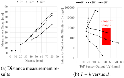
Fig. 12. Distance measurement results when tilting the sensor relative to the A5052 plate, and a semi-logarithmic plot of the relationship between \(d_{\rm T}\) and \(I-b\). The format of (a) is nearly the same as Fig. 11, but as in Fig. 8, points where \(d_{\rm c}\) became erroneous value (NaN) is not plotted. In (b), the mean of \(d_{\rm T}\) and mean of \(I-b\) at distances where \(d_{\rm T}\) never became an erroneous value across 100 measurements are plotted within the range shown on the semi-logarithmic graph. The red region in (b) indicates the range of Stage 2 (i.e., the stage where the object-dependent parameter \(a\) is acquired). Looking at (a), when \(\theta\ne0°\), the distance error and frequency of erroneous values in \(d_{\rm c}\) are reduced compared to when \(\theta=0°\). On the other hand, looking at (b), at \(\theta=60°\), \(a\) was never acquired, indicating that \(d_{\rm c}\) depended on \(d_{\rm T}\).
The distance measurement results are shown in Figs. 11 and 12. Even when the sensor was tilted relative to the measurement target, the measured distances did not deviate significantly. For the pink and green papers, \(d_{\rm c}\) decreased as \(\theta\) increased. This is likely because the irradiation range of the ToF sensor spreads rather than remaining at a point. As \(\theta\) increased, the edge of the irradiation range became closer to the sensor than the center of the irradiation range and \(d_{\rm T}\) was considered to become smaller owing to the influence of reflections from there. As \(d_{\rm T}\) became smaller, the acquisition of the object-dependent parameter \(a\) was affected, and \(d_{\rm I}\) also became smaller, which is considered to result in the overall \(d_{\rm c}\) becoming smaller. On the other hand, for the black paper, the change in \(d_{\rm c}\) accompanying the change in \(\theta\) was small, showing that this change became smaller when the reflectance was low. Regarding the A5052 plate, when \(\theta\ne0°\), the distance error and frequency of erroneous values in \(d_{\rm T}\) were reduced compared to when \(\theta=0°\), resulting in an overall improvement in \(d_{\rm c}\). On the other hand, at \(\theta=60°\), \(a\) was never acquired, making it impossible to use \(d_{\rm I}\). This revealed the limitations for objects with specular reflectance.
5. Application of WrPPS
This section presents grasping of compliant objects, tactile sensing in a stuffed robot, slip detection during walking, and agricultural plant sensing as applications of the WrPPS, demonstrating the wide applicability of WrPPS.
5.1. Grasping of Compliant Objects
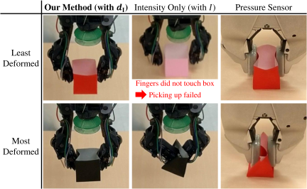
This subsection describes an application example of grasping compliant objects without damaging them using the WrPPS. The details of this subsection can be found in our previous letter paper 19. In this example, during the grasping motion of a robot hand with WrPPS built into its fingertips, we monitored \(d_{\rm I}\) output from WrPPS. When all values fell below a threshold, a command to stop the fingers was issued, creating a state where the fingertips touched the object gently enough not to crush it, yet firmly enough to lift it.
We conducted five picking-up trials using our precise grasping system against 12 compliant colored boxes. Their compliance came from the thinness of their paper walls (i.e., 0.07 mm). In each trial, we checked if the robot grasped the object gently enough not to squeeze it and firmly enough to lift it up. In addition to the trials using our system, the following cases were tested for comparison:
-
picking up only with the intensity sensors against the black and pink boxes, and
-
grasping with pressure sensors against the red box.
In the former, our robot hand stopped its fingers when every intensity output with the offset fell below the threshold uniquely defined for each sensor. In the latter, we used the Willow Garage PR2 robot with its pressure sensor fingertips. We utilized the standard PR2 gripper sensor controller with the same thresholds as in the previous study 9.
Table 1 shows the results of the task involving the picking up of compliant objects. The deformations by our precise grasping system were smaller than those by the other methods. In addition, our precise grasping was gentle and firm against all box colors.
Table 1. Object deformations caused by the grasping motions. © 2020 IEEE. Reprinted, with permission, from 19. We selected pictures of the least and most deformed objects in all trials of each method. The deformations by our precise grasping system were smaller compared to those by the other methods.
5.2. Tactile Sensing in a Stuffed Robot
5.2.1. Design of a Tactile Stuffed Robot
For immersive human-robot interaction with a stuffed robot 21,22, we integrated the WrPPS Single Board to allow a response to being touched by humans. Fig. 13 shows the method for integrating the WrPPS Single Board. By integrating the boards at four locations (i.e., front of the head, back of the head, and both hands), contact can be detected when a person strokes the robot’s head or holds its hands. To mount the sensor boards, the three holes described in Section 3.1 were used. Secure mounting of the sensor boards was achieved by threading strings through these holes and sewing them onto the outer skin. Because the sensor board was compact, the inhibition of the flexibility of the outer skin caused by sewing it was suppressed. In addition, because the sensor board was thin, no protrusions were formed on the stuffed robot surface, thereby suppressing the sense of discomfort when stroking. These properties helped maintain the stuffed toy’s natural appearance and feel during human-robot interaction.
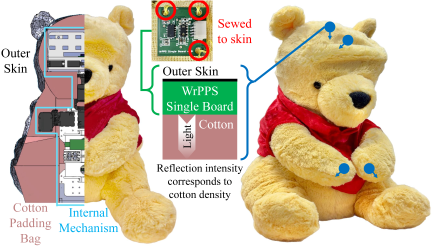
Fig. 13. Stuffed robot with the WrPPS Single Board integrated for tactile sensing. The sensor boards are integrated at four locations: front of head, back of head, and both hands. Each detection surface faces inward toward the body, detecting contact around the sensor boards by sensing changes in the density of the cotton through which the sensor light passes.
5.2.2. Stroke Detection Experiment
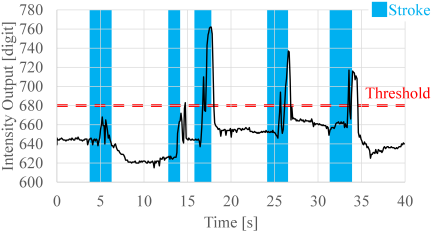
Fig. 14. Back-of-head sensor values during the stroke detection experiment. Blue regions indicate the periods of stroking motions, and the red dashed line indicates the contact detection threshold. The first and second stroking motions were not detected, while the third and subsequent motions were detected. Checking the front-of-head sensor for the first and second motions, contact was detected in the first but not in the second. Combining both sensors, contact was detected in four out of five cases.
We conducted an experiment in which the robot moved in response to a person stroking its head. In the experiment, the robot responded to four of five stroking motions (Fig. 14), confirming that even soft contact when stroking a stuffed toy could be detected. Even in the only motion where contact was not detected, there was a sensor response. Therefore, this can be addressed by improving the contact detection method.
5.2.3. Evaluation at a Well-Attended Exhibition
We conducted a 4-day exhibition of an artwork that displayed visuals corresponding to the body part touched by a person on the stuffed robot. A total of 905 visitors attended the exhibition, most of whom visited this artwork. To the best of our knowledge, everyone who touched the robot experienced the visual presentation, demonstrating the practicality of this usage of the WrPPS Single Board. In addition, there was no sensor system failure, demonstrating the durability of the WrPPS Single Board.
5.3. Slip Detection During Walking
5.3.1. Concept of Slip Detection for Walking Hand
In humanoid robot hands that walk independently using fingers as legs 23,24, the motion frequently involves dragging the palm, and the body weight is not easily applied to the fingertip contact points. Therefore, the fingertips tend to slip on the ground, and detecting this slip and correcting gait are important.
5.3.2. Walking Hand Prototype
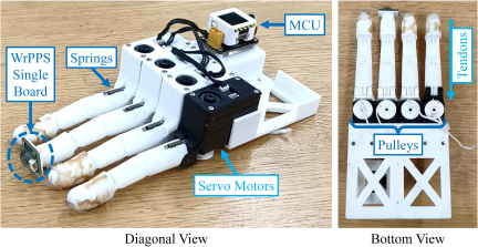
Fig. 15. Hand prototype for verifying whether slip detection during hand-only walking is possible using a proximity sensor. The WrPPS Single Board is attached to the fingertip of the middle finger.
Figure 15 shows a 4-finger hand for walking with the index, middle, ring, and little fingers with the WrPPS Single Board attached to the fingertip of the middle finger. The surface of the sensor board was covered with a flexible UV-curing resin (LED Curing Resin “Star Drop” Gummy, PADICO) to allow frictional contact with the ground. Because the sensor board was compact, it was possible to attach it to the small fingertip and execute the same walking motion as before the sensor board was attached.
5.3.3. Slip-Detection Experiments
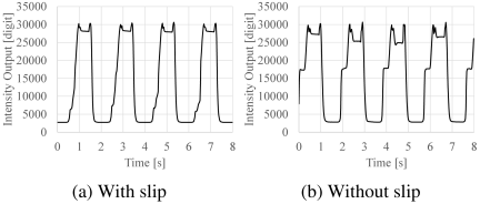
Fig. 16. Proximity sensor values in the slip-detection experiments. The waveforms differ significantly between cases with and without slip, making them distinguishable.
We conducted slip-detection experiments during the walking motion (Fig. 16). The sensor value waveforms differed significantly between the cases with and without slip, confirming that they were distinguishable. In addition, walking motions were performed for four cycles each, and the difference in waveforms between cycles was small, confirming that stable discrimination was possible.
5.4. Agricultural Plant Sensing
5.4.1. Concept of Proximity Sensing of Agricultural Plants
We aim to combine proximity sensors with cameras for plant perception so that parts occluded from the camera as the end effector approaches can continue to be recognized. In addition, by allowing the sensor-equipped part to move into the vegetation, we seek to capture the detailed structure of even densely growing plants.
5.4.2. Agricultural Plant Sensing Experiments
Therefore, it is necessary for proximity sensors to detect plant branches (i.e., thin objects). In proximity sensor research, there are examples of pen slippage detection using visual sensing 13 and electrical wire detection using ToF sensing 25. However, these were limited to detecting objects within a close range of less than 40 mm, and the detection performance for more distant objects was unclear. Therefore, we investigated whether the intensity and ToF sensors could detect plant branches using the WrPPS Single Board. The experimental setup is shown in Fig. 17. The detection target was an actual grapevine stick (diameter 10 mm). The stick was placed directly in front of the sensor board, and while varying the distance from the sensor board, the intensity and ToF sensor values were measured 50 times at each distance. The minimum distance was 10 mm and the maximum was 100 mm, and measurements were taken in 10 mm increments. The experimental results are shown in Fig. 18. It was observed that both the intensity and ToF sensors could detect the stick. However, the ToF sensor output distances greater than the actual distance, indicating reduced accuracy.
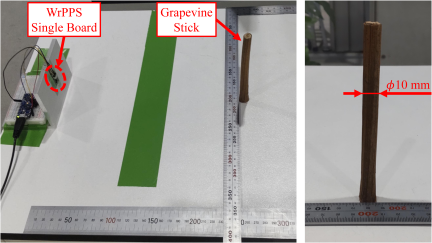
Fig. 17. Setup for the agricultural plant sensing experiments. The detection target is an actual grapevine stick (diameter 10 mm).
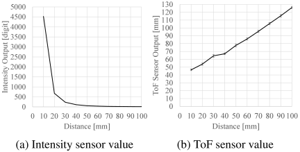
Fig. 18. Results of the agricultural plant sensing experiments. This graph was created by linear interpolation of the average of 50 measurements at each distance. Each error bar represents the standard deviation of the 50 measurements. In (a), error bars were omitted because they were small enough to overlap with the graph line width. Both the intensity and ToF sensors were able to output values related to the distance from the grapevine stick, while the ToF sensor output distances greater than the actual distance.
6. Conclusion
In this study, we defined a proximity sensor based on the fusion of an optical reflection intensity sensor and optical ToF sensor as a WrPPS. This sensor can detect objects over a wide range from close to long distances, has low dependence on the physical properties of the detected object, and can be configured compactly enough to be mounted in narrow spaces, such as the fingertips of human-sized robot hands. To allow the broad application of this sensor, we proposed the WrPPS Single Board that packages the minimal configuration of this sensor (i.e., a combination of one intensity sensor and one ToF sensor) onto a compact \(18~\rm{mm}\times18~\rm{mm}\) printed circuit board, allowing application wherever this board can be mounted. Furthermore, to improve the accessibility of this board in terms of both hardware and software and allow easy application by anyone, we sold the board at a low price and released the fusion of the intensity and ToF sensors as open-source software implemented in a format that is easy to integrate into robots. We quantitatively evaluated the distance measurement performance of this sensor over a broad range, including cases targeting objects with specular reflectance, curved surface geometry, and tilt relative to the sensor, and confirmed its superiority over the ToF sensor alone and the intensity sensor alone. As practical examples of the application of this sensor, we presented grasping of compliant objects, tactile sensing in a stuffed robot, slip detection during walking, and agricultural plant sensing, demonstrating its wide applicability.
- [1] A. R. Johnston, “Proximity sensor technology for manipulator end effectors,” Mechanism and Machine Theory, Vol.12, Issue 1, pp. 95-109, 1977. https://doi.org/10.1016/0094-114X(77)90061-1
- [2] R. Patel, R. Cox, and N. Correll, “Integrated proximity, contact and force sensing using elastomer-embedded commodity proximity sensors,” Autonomous Robots, Vol.42, No.7, pp. 1443-1458, 2018. https://doi.org/10.1007/s10514-018-9751-4
- [3] S. Hasegawa, K. Wada, K. Okada, and M. Inaba, “A Three-Fingered Hand with a Suction Gripping System for Warehouse Automation,” J. Robot. Mechatron., Vol.31, No.2, pp. 289-304, 2019. https://doi.org/10.20965/jrm.2019.p0289
- [4] K. Koyama, M. Shimojo, A. Ming, and M. Ishikawa, “Integrated control of a multiple-degree-of-freedom hand and arm using a reactive architecture based on high-speed proximity sensing,” The Int. J. of Robotics Research, Vol.38, Issue 14, pp. 1717-1750, 2019. https://doi.org/10.1177/0278364919875811
- [5] S. Armleder, F. Bergner, J. R. Guadarrama-Olvera, J. Nakanishi, and G. Cheng, “Real-Time Control of a Humanoid Robot for Whole-Body Tactile Interaction,” Advanced Intelligent Systems, Vol.7, Issue 12, Article No.e2500149, 2025. https://doi.org/10.1002/aisy.202500149
- [6] R. Wistort and J. R. Smith, “Electric field servoing for robotic manipulation,” 2008 IEEE/RSJ Int. Conf. on Intelligent Robots and Systems, pp. 494-499, 2008. https://doi.org/10.1109/IROS.2008.4650721
- [7] P. E. Lancaster, J. R. Smith, and S. S. Srinivasa, “Improved Proximity, Contact, and Force Sensing via Optimization of Elastomer-Air Interface Geometry,” 2019 Int. Conf. on Robotics and Automation (ICRA), pp. 3797-3803, 2019. https://doi.org/10.1109/ICRA.2019.8793959
- [8] U. Nunes, P. Faia, and A. T. de Almeida, “Sensor-based 3-D autonomous contour-following control,” Proc. of IEEE/RSJ Int. Conf. on Intelligent Robots and Systems (IROS’94), Vol.1, pp. 172-179, 1994. https://doi.org/10.1109/IROS.1994.407394
- [9] L.-T. Jiang and J. R. Smith, “Seashell effect pretouch sensing for robotic grasping,” 2012 IEEE Int. Conf. on Robotics and Automation, pp. 2851-2858, 2012. https://doi.org/10.1109/ICRA.2012.6224985
- [10] D. Guo, P. Lancaster, L.-T. Jiang, F. Sun, and J. R. Smith, “Transmissive optical pretouch sensing for robotic grasping,” 2015 IEEE/RSJ Int. Conf. on Intelligent Robots and Systems (IROS), pp. 5891-5897, 2015. https://doi.org/10.1109/IROS.2015.7354214
- [11] G. B. Avanzini, N. M. Ceriani, A. M. Zanchettin, P. Rocco, and L. Bascetta, “Safety Control of Industrial Robots Based on a Distributed Distance Sensor,” IEEE Trans. on Control Systems Technology, Vol.22, Issue 6, pp. 2127-2140, 2014. https://doi.org/10.1109/TCST.2014.2300696
- [12] S. Chen, H. Guo, T. P. Tomo, S. Somlor, A. Schmitz, and S. Sugano, “Optimized Frequency Modulated Continuous Wave Radar Configuration for Proactive Collision Avoidance in Collaborative Robots,” 2025 IEEE/ASME Int. Conf. on Advanced Intelligent Mechatronics (AIM), 2025. https://doi.org/10.1109/AIM64088.2025.11175758
- [13] A. Yamaguchi and C. G. Atkeson, “Tactile Behaviors with the Vision-Based Tactile Sensor FingerVision,” Int. J. of Humanoid Robotics, Vol.16, No.03, Article No.1940002, 2019. https://doi.org/10.1142/S0219843619400024
- [14] K. Koyama, M. Shimojo, T. Senoo, and M. Ishikawa, “High-Speed High-Precision Proximity Sensor for Detection of Tilt, Distance, and Contact,” IEEE Robotics and Automation Letters, Vol.3, Issue 4, pp. 3224-3231, 2018. https://doi.org/10.1109/LRA.2018.2850975
- [15] K. Sasaki, K. Koyama, A. Ming, M. Shimojo, R. Plateaux, and J.-Y. Choley, “Robotic Grasping Using Proximity Sensors for Detecting both Target Object and Support Surface,” 2018 IEEE/RSJ Int. Conf. on Intelligent Robots and Systems (IROS), pp. 2925-2932, 2018. https://doi.org/10.1109/IROS.2018.8594430
- [16] T. D. Nguyen, T. Kim, J. Noh, H. Phung, G. Kang, and H. R. Choi, “Skin-Type Proximity Sensor by Using the Change of Electromagnetic Field,” IEEE Trans. on Industrial Electronics, Vol.68, Issue 3, pp. 2379-2388, 2021. https://doi.org/10.1109/TIE.2020.2975503
- [17] H. Kang, H. Yim, H. Sung, and H. R. Choi, “Adaptive Measurement Model-Based Fusion of Capacitive Proximity Sensor and LiDAR for Improved Mobile Robot Perception,” IEEE Robotics and Automation Letters, Vol.10, Issue 1, pp. 836-843, 2025. https://doi.org/10.1109/LRA.2024.3511432
- [18] S. Tsuji, “Wrap-Around String-Like ToF and Self-Capacitance Combined Sensor for Robots,” IEEJ Trans. on Electrical and Electronic Engineering, Vol.20, Issue 5, pp. 688-695, 2025. https://doi.org/10.1002/tee.24232
- [19] S. Hasegawa, N. Yamaguchi, K. Okada, and M. Inaba, “Online Acquisition of Close-Range Proximity Sensor Models for Precise Object Grasping and Verification,” IEEE Robotics and Automation Letters, Vol.5, Issue 4, pp. 5993-6000, 2020. https://doi.org/10.1109/LRA.2020.3010440
- [20] S. Tokiwa, H. Arita, Y. Suzuki, K. Nakashima, and K. Tahara, “Simultaneous multi-finger contact independent of reflectance using a hybrid proximity sensor combining reflected light intensity and time-of-flight,” Proc. of 2025 JSME Annual Conf. on Robotics and Mechatronics, 1A2-M02, 2025 (in Japanese).
- [21] A. Nagata, T. Makabe, I. Yanokura, and K. Okada, “Development of a Robot that Balances Plush-like Appearance and Animacy: Eyebrow Expression through Surface Deformation and Softness through Cotton Padding Bag,” Proc. of 2025 JSME Annual Conf. on Robotics and Mechatronics, 2P1-H10, 2025 (in Japanese). https://doi.org/10.1299/jsmermd.2025.2P1-H10
- [22] A. Nagata, T. Sawada, A. Ichikura, Y. Obinata, N. Kanazawa, T. Makabe, I. Yanokura, and K. Okada, “Design and Evaluation of Engaging Storytelling Experience through Interactive Scripted Performance with a Character Robot,” 2025 34th IEEE Int. Conf. on Robot and Human Interactive Communication (RO-MAN), pp. 1531-1536, 2025. https://doi.org/10.1109/RO-MAN63969.2025.11217727
- [23] X. Gao, K. Yao, K. Junge, J. Hughes, and A. G. Billard, “A Robotic Hand Surpassing Human Capabilities in Dexterity and Functionality,” 2025. https://doi.org/10.21203/rs.3.rs-5538062/v1
- [24] A. Nakane, N. Yamaguchi, I. Yanokura, and K. Okada, “Embodied functional specialization for task-driven five-fingered hand-locomanipulation,” 26th Conf. of the Society of Instrument and Control Engineers (SICE), System Integration Division, 2B3-09, 2025 (in Japanese).
- [25] A. Cirillo, G. Laudante, and S. Pirozzi, “Wire Grasping by Using Proximity and Tactile Sensors,” 2022 IEEE 5th Int. Conf. on Industrial Cyber-Physical Systems (ICPS), 2022. https://doi.org/10.1109/ICPS51978.2022.9816936
- [a] SparkFun Electronics, “Robotic Finger Sensor,” 2017. https://www.sparkfun.com/products/14200 [Accessed June 26, 2017]
- [b] Tokyo Opensource Robotics Kyokai Association, “Light Proximity Sensor Module WrPPS Single Board Now Available,” 2025 (in Japanese). https://opensource-robotics.tokyo.jp/?p=8755 [Accessed November 24, 2025]
- [c] SparkFun Electronics, “Robotic Finger Sensor v2,” 2025. https://www.sparkfun.com/robotic-finger-sensor-v2.html [Accessed July 28, 2025]
- [d] MONOist, “Proximity sensor that gives robot hands a brain is finally entering mass production, with a July 2023 release date,” 2023 (in Japanese). https://monoist.itmedia.co.jp/mn/articles/2305/17/news075.html [Accessed November 24, 2025]
- [e] SparkFun Electronics, “Qwiic,” 2025. https://www.sparkfun.com/qwiic [Accessed November 24, 2025]
- [f] Tokyo Opensource Robotics Kyokai Association, “wrpps_ros,” 2025. https://github.com/tork-a/wrpps_ros [Accessed November 24, 2025]
- [g] Kawada Robotics, “NEXTAGE – A next-generation robot able to work together with people,” 2013. http://nextage.kawada.jp/en/ [Accessed March 2, 2026]
- [h] VISHAY, “Designing the VCNL4040 Into an Application,” 2025. https://www.vishay.com/docs/84307/designingvcnl4040.pdf [Accessed March 4, 2026]
- [i] STMicroelectronics, “World’s smallest time-of-flight ranging and gesture detection sensor,” 2018. https://www.st.com/resource/en/datasheet/vl53l0x.pdf [Accessed February 18, 2020]
This article is published under a Creative Commons Attribution-NoDerivatives 4.0 Internationa License.