
Paper:
Proximity and Contact Sensor Combining Multi-Zone ToF Sensors and a Self-Capacitance Sensor
Satoshi Tsuji

Department of Electrical Engineering, Fukuoka University
8-19-1 Nanakuma, Jonan-ku, Fukuoka, Fukuoka 814-0180, Japan

In recent years, collaborative robots (cobots) that can operate safely with humans have gained popularity. Proximity and tactile sensors contribute to the safe operation of cobots in shared workspaces. This study proposes a time-of-flight (ToF) sensor and self-capacitance proximity and contact sensor that combines five wide field-of-view multi-zone ToF sensors with a self-capacitance electrode, allowing for installation on curved surfaces such as non-driven regions near joints and achieving wide-range measurements from proximity to contact. The combination of ToF and self-capacitance sensing allows seamless detection from non-contact to contact with fewer blind spots. Furthermore, real-time control based on the acquired data was implemented, demonstrating improved safety and operational efficiency during collaborative tasks by reducing robot speed and stopping its motion when proximity is detected. The proposed method allows for both curved-surface installation, including non-driven regions near joints, and continuous detection of proximity to contact in cobot safety systems.
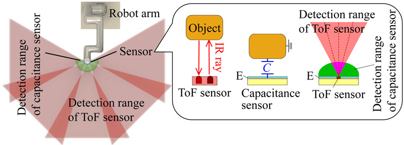
Proposed sensor mounted near a robot joint during measurement
1. Introduction
In recent years, collaborative robots (cobots) that can operate safely in workspaces shared with humans have attracted considerable attention. Sensors play a critical role in ensuring safety. Sensors used for cobot safety can be categorized into three types: external, internal, and surface-mounted. External sensors include systems that use 3D cameras installed outside the robot to measure the surrounding environment 1,2, and LiDAR sensors 3. These systems are effective for object detection around robots; however, robot motion may cause self-occlusion and create blind spots. Although multiple cameras can be used to eliminate blind spots, the integration of multiple images requires complex processing techniques. Internal sensors are also commercially available, allowing for contact detection within the cobots a. These sensors detect collisions and immediately stop the robot from mitigating their impacts. However, the retrofitting of such systems to existing robots is challenging.
Surface-mounted sensors have recently attracted attention as effective safety sensors because they are less affected by motion-induced blind spots and can be applied to existing robots. These include tactile sensors 4,5,6,7,8, proximity sensors 9,10,11,12, and hybrid proximity and tactile sensors 13,14,15,16,17. Tactile sensors primarily detect contact conditions, particularly contact pressure, and can reduce the impact through feedback control. However, because they detect objects only after contact, their motion speed must be limited to prevent damage. Non-contact proximity sensors capable of detecting objects before contact have been proposed 9,10,11. We previously developed a proximity-sensing system using multiple time-of-flight (ToF) sensors to measure the distance to surrounding objects 12. This system allows proximity awareness and collision avoidance; however, conventional proximity sensors are incapable of detecting contact.
Several proximity and tactile sensors capable of measuring the proximity to contact have been developed 13,14,15,16. Although sensors that use only the mutual capacitance to measure proximity and contact 13 are useful, it is difficult to extend the detection range by relying solely on the mutual capacitance. Sensors that combine multiple sensing elements to measure both proximity and contact have been proposed 14; however, blind spots may occur in proximity measurements near the sensor. Although a sensor combining a ToF sensor and contact sensor has been proposed 15,16, measuring the proximity state near the contact sensor remains difficult. Sensors that combine a ToF sensor with impedance-measurement-based non-contact capacitance sensing have also been proposed 17. However, this capacitive measurement requires a pair of electrodes, one for sensing and the other for grounding, and the detection sensitivity may decrease near the grounding electrode. In addition, contact detection has not been considered in this study. We previously proposed a self-capacitance proximity and tactile sensor 18 and a ToF and self-capacitance proximity and contact sensor 19. The integration of the ToF and self-capacitance sensing allows wide-area measurements with reduced blind spots. Furthermore, a string-like flexible sensor was developed to allow wrapping installations on the robot surfaces 20. However, it is difficult to wrap ToF sensors around non-driven parts near robot joints, and to measure over a wide area without blind spots, it is required to install a large number of ToF sensors.
The objective of this study, as shown in Fig. 1, is to establish a sensor system that can be mounted on a cobot surface and accurately measure the proximity and contact states. To reduce blind spots during non-contact measurements, a wide field-of-view (FoV) multi-zone ToF sensor with a multi-zone structure was used, allowing wide-area detection with fewer ToF sensors. In addition, large electrodes were used for self-capacitance measurements to extend the \(Z\)-axis detection range and minimize blind spots through ToF and capacitance integration. Although conventional single-zone ToF sensors provide reduced costs and shorter sampling times, a small number of wide FoV multi-zone ToF sensors were used in this study to provide wide-area detection. The sensor system consisted of five multi-zone ToF sensors and a single self-capacitance sensor electrode. Consequently, ToF sensors can detect the position of objects in three dimensions, whereas self-capacitance sensors can only detect whether an object is nearby or in contact. Although the number of self-capacitance sensor electrodes could be increased, in this study, the electrodes were enlarged to prioritize coverage of the blind spots of the ToF sensors, which also expanded the detection area. The novelty of this study lies in the achievement of wide-area sensing by combining a limited number of multi-zone ToF sensors with self-capacitance sensors.
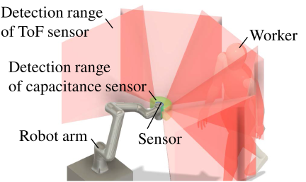
Fig. 1. Image of the proposed sensor mounted on a non-driven part near the robot joint during measurement. The sensor allows seamless measurements from the proximity range to the contact state.
Experiments using a prototype sensor were conducted to evaluate the proximity measurement, contact detection, and proximity detection range. The sensor system was implemented on a robot arm, and robot control was performed based on the acquired data. The results demonstrated that the proposed sensor system was effective for cobot safety applications.
2. ToF and Self-Capacitance Combined Proximity and Tactile Sensor
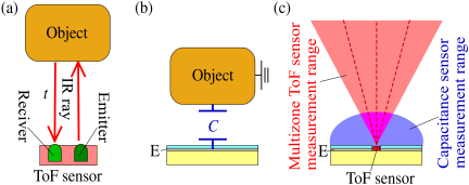
Fig. 2. Proposed sensing methods. (a) The ToF sensor detects the distance to an object based on the reflection time of emitted light. (b) Self-capacitance sensors perform contactless measurements and determine the presence or absence of touch by detecting changes in capacitance. (c) By combining a ToF sensor with a capacitive sensor, proximity measurement can be achieved with minimal blind spots.
The purpose of this study was to establish a sensing system that could measure objects in the proximity range of the surface of a cobot without any blind spots as a safety measure for the cobot and could detect contact. We previously proposed a ToF and self-capacitance proximity and contact sensor that combines ToF and self-capacitance sensors 18. The ToF sensor measures the distance to an object by calculating the time interval between the emission of infrared light and reception of the reflected signal, as shown in Fig. 2(a). Compared to the self-capacitance measurement, the ToF sensor provides a wider detection range along the \(Z\)-axis and allows distance measurement. However, its accuracy deteriorates at short distances, and the detection range in the \(X\)–\(Y\) range is limited because of the light emission angle. A self-capacitance sensor detects nearby objects by measuring the change in capacitance between a single electrode and ground, as shown in Fig. 2(b). This change can also be used to detect contact, similar to the operation of touch panels. By combining ToF and self-capacitance sensing, continuous and blind-spot-free measurements from long to short distances can be achieved, as shown in Fig. 2(c) 18.
The ToF sensor used in our previous study 18,19 had an approximate FoV of 25°, which required multiple sensors to perform non-contact measurements without blind spots. Another study 16 used multiple multi-zone ToF sensors with a 45° FoV as proximity sensors for robots; however, because only ToF sensors and contact sensors were used, blind spots may have occurred in the near non-contact region. In this study, a wider measurement range was achieved with fewer sensors using a multi-zone ToF sensor with a wider FoV in combination with a self-capacitance sensor. Furthermore, we previously proposed a string-shaped sensor structure that allows flexible implementation of sensors. However, it remains difficult to install them in areas where wrapping is difficult, such as non-driven parts near robot joints. In this study, we focused on sensing systems designed to be installed on non-driven parts near robot joints.
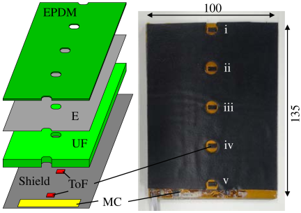
Fig. 3. Schematic of the prototype sensor. E: electrode, UF: urethane foam, MC: measuring circuit, EPDM: EPDM rubber, i–v: ToF sensors i–v.
Figure 3 shows the prototype sensor. The prototype sensor included a single electrode and five ToF sensors, with 30 mm of spacing between the adjacent ToF sensors. The sensor was mounted on a curved surface near the five-axis joint section of the Nova 5 robot (Dobot Robotics). The number, spacing, and configuration of the ToF sensors and electrodes were modified based on the geometry of the robot. In this study, a VL53L7CX (STMicroelectronics) b was used as the ToF sensor. The VL53L7CX provides a square FoV of 60° \(\times\) 60° and supports multi-zone operation, allowing distance measurement in either \({8 \times 8}\) or \({4 \times 4}\) matrix formats. Considering the intended application as a proximity sensor for robots, a \({4 \times 4}\) matrix mode, which provides a higher sampling rate, was selected. The specified detection range for VL53L7CX was 3,500 mm. As shown in Fig. 3, five ToF sensors (ToF sensors i–v) were mounted on the flexible polyimide substrates. To reduce the electrical noise, the area surrounding each ToF sensor was connected to the same potential as that of the sensing electrode and used as a shield. The flexible substrate measured \({135 \times 100}\) mm. For impact absorption, a 3 mm thick urethane foam (UF) layer was placed on top of the flexible substrate. A self-capacitance-sensing electrode (E) measuring \({130 \times 100}\) mm was positioned above the foam. An EPDM rubber sheet (thickness \(=\) 0.5 mm) was added on top of the electrode to provide insulation between the electrode and object. Holes were created in the UF, E, and EPDM to allow the infrared light emitted from the ToF sensors to pass through. For self-capacitance measurements, a capacitive-to-digital converter AD7147 (Analog Devices) was used. A measurement circuit (MC), including AD7147, was mounted on a flexible substrate. A 3 mm thick UF layer was used, which was considered to contribute significantly to the bending stiffness of the sensor. Although reducing or removing the UF layer would increase the sensor flexibility, a 3 mm thick UF layer was used in this study to absorb the impact during collisions and reduce electrical noise from the ToF sensors. A microcontroller was used to control both the ToF sensors and AD7147. The total measurement time of the prototype sensor was approximately 71 ms, corresponding to a sampling frequency of approximately 14 Hz. Most of the measurement time was obtained from measurements using the five ToF sensors. Although the sampling frequency of the sensor was not high, the ToF sensor could detect objects from a distance and was therefore considered unlikely to pose a problem for safety measures.
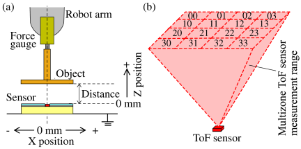
Fig. 4. Experimental conditions. (a) Experimental equipment. (b) Multi-zone ranging measurement with \({4 \times 4}\) separate zones.
3. Results and Discussion
3.1. \(Z\)-axis Measurement of Prototype Sensor
Experiments were conducted to verify the \(z\)-axis measurement capability of the prototype sensor. The sensor characteristics on a flat surface were examined for a fundamental evaluation. The prototype sensor was placed on an acrylic base plate with a thickness of 3 mm, and a grounded aluminum plate was positioned on the backside of the acrylic base. As shown in Fig. 4(a), the object was attached to a robot arm (VS-050, DENSO) to control the relative position between the sensor and object. The VS-050 has a positional repeatability of \(\pm\)0.02 mm, which is higher than that of the Nova 5 robot (\(\pm\)0.05 mm) where the sensor is intended to be implemented; therefore, the VS-050 was used for the fundamental experiment. The contact between the sensor and object was detected using a force gauge (AD4932A-50N, A&D) mounted on the robot arm. Two object sizes were prepared: one with dimensions of \({130 \times 100}\) mm (denoted as 130 mm), corresponding to the size of the sensor electrode, and the other with dimensions of \({30 \times 30}\) mm (denoted as 30 mm). The centers of the sensor and object were aligned along the \(X\)–\(Y\) plane, and the position at which the object touched the sensor was defined as \(Z = 0\) mm. To investigate the influence of the electrical properties of an object on the self-capacitance measurement, two types of objects were used: a grounded conductor (GND) and an acrylic plate. It should be noted that, in self-capacitance measurements, a human body exhibits similar electrical characteristics to a GND. To evaluate the effect of surface reflectivity on ToF sensing, white paper with a high reflectivity and black paper with a low reflectivity were attached to the surface of the object. The VL53L7CX allows for \(4 \times 4\) multi-zone distance measurements (ranging from 00 to 33), as shown in Fig. 4(b), based on the configuration settings. In this experiment, the measured value from zone 11 of the \(4 \times 4\) array was used.
Figure 5 shows the experimental results. Fig. 5(a) shows the distance (\(D\)) measured by the ToF sensor iii of the prototype, and Fig. 5(b) shows an enlarged view of Fig. 5(a). As shown in Fig. 5(a), \(D\) varied with distance for both white and black objects, indicating that the distance to an object can be measured independently of its surface reflectivity. The VL53L7CX ToF sensor has a specified measurable range of up to 3,500 mm. Although the measurable distance is based on the reflectivity of the object, detection is possible even when it is located more than 500 mm away. However, when the object was closer than 5 mm, the infrared return time was extremely short, resulting in large measurement errors, as shown in Fig. 5(b). Therefore, although the ToF sensor can determine whether an object is within approximately 10 mm, it is difficult to detect the contact.
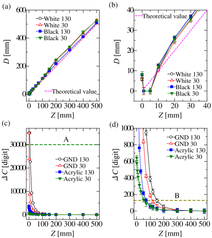
Fig. 5. Measurement results in the \(Z\)-axis. (a) Distance measured (\(D\)) by the ToF sensor. (b) Enlarged view of (a). (c) Measurement by the self-capacitance sensor (\({\Delta C}\)). (d) Enlarged view of (c). The dashed line labeled A indicates the threshold for contact detection of the self-capacitance sensor, while the dashed line labeled B indicates the threshold for proximity detection. Data are represented as mean \(\pm\) SD (\(n = 30\)).
Figure 5(c) shows the variation in capacitance (\({\Delta C}\)) from the steady-state value measured by the self-capacitance sensor, and Fig. 5(d) shows an enlarged view of Fig. 5(c). The value of \({\Delta C}\) increased as the distance between the object and the sensor decreased. The capacitance variation was based not only on the distance to the object but also on the electrical properties of the object, its overlap with the electrode, and its shape. Therefore, it was difficult to determine the object distance based solely on the capacitance variation. However, because \({\Delta C}\) changed as the object approached, it could be used to detect the presence of an object under non-contact conditions. When a GND contacted or approached the sensor, \({\Delta C}\) increased significantly. In addition, when a human touched the sensor, the \({\Delta C}\) value was almost equivalent to that of a GND. This indicates that contact by a human can be detected using \({\Delta C}\), similar to the operation of a touch panel. In the present experiment, the standard deviation (\(\sigma\)) of \({\Delta C}\) at a distance of 500 mm was 24.5 digits. In this study, non-contact detection was defined as the condition where \({\Delta C}\) exceeded \(5\sigma\), which was to threshold B. Under this condition, a GND (130) was detected at approximately 150 mm, a GND (30) at approximately 100 mm, an acrylic (130) at approximately 70 mm, and an acrylic (30) at approximately 50 mm. The standard deviation of \({\Delta C}\) was influenced by environmental factors, including electrical noise. Consequently, the non-contact detection range determined by threshold B varied with changes in the environment. Furthermore, when \({\Delta C}\) exceeded 30,000 digits, which was threshold A, the object was determined to be in contact with the sensor. This threshold A is defined by assuming that the object is a human or a GND; therefore, contact cannot be detected for dielectric materials such as acrylic. The threshold values were adjusted based on the measurement environment.
Thus, although a ToF sensor can detect the presence of an object in close proximity, it is difficult to identify contacts accurately using ToF sensing alone. In contrast, as discussed above, contact with GNDs, including humans, can be effectively detected based on the variation in \({\Delta C}\) obtained from self-capacitance measurement. Therefore, by combining a ToF sensor with a self-capacitance sensor, high-sensitivity measurements can be achieved continuously from non-contact to contact conditions 18.
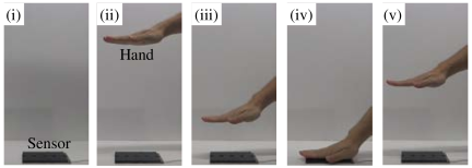
Fig. 6. Continuous measurement. The hand is moved continuously along the \(Z\)-axis.
3.2. Continuous Measurement of Prototype Sensor on the \(Z\)-axis
Continuous measurements were performed when an object was moved along the \(Z\)-axis using a prototype sensor. As shown in Fig. 6, the sensor was placed on a flat surface, and a hand was brought close to the sensor, touched, and moved away. Fig. 7(a) shows the distance \(D\) measured by the ToF sensor iii of the prototype. In this experiment, the measured value from zone 11 of the \({4 \times 4}\) array was used. As shown in Fig. 7(a), the distance to the object was continuously measured during movement. However, under the contact conditions, \(D\) exhibited little variation. Fig. 7(b) shows the variation in capacitance (\({\Delta C}\)) measured by the prototype sensor, and Fig. 7(c) shows an enlarged view of Fig. 7(a). As shown in Figs. 7(b) and (c), non-contact detection was achieved when \({\Delta C}\) was greater than or equal to threshold B. Furthermore, when the object was in contact with the sensor (0 mm), contact detection could also be achieved based on the variation in \({\Delta C}\), that is, when \({\Delta C}\) was greater than or equal to threshold A. These results demonstrate that by combining the ToF and self-capacitance sensors, continuous and seamless measurement of an object can be achieved from non-contact to contact conditions.
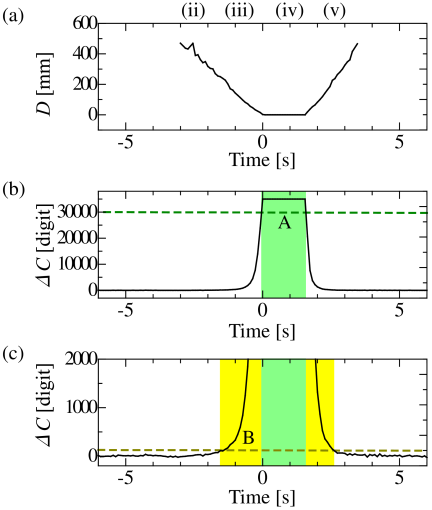
Fig. 7. Measurement results when the hand is moved continuously in the \(Z\)-axis. (a) Distance measured (\(D\)) by the ToF sensor. (b) Measurement by the self-capacitance sensor (\({\Delta C}\)). (c) Enlarged view of (b). The dashed lines A and B indicate the contact and proximity detection thresholds of the self-capacitance sensor, respectively. The green and yellow areas represent contact and non-contact detection periods, respectively. (ii)–(v) correspond to items (ii)–(v) in Fig. 6.
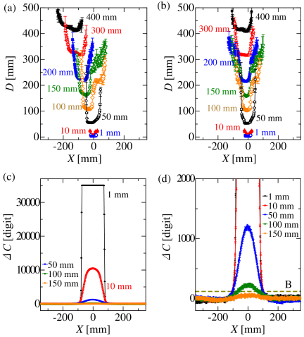
Fig. 8. Measurement results of the object moving at \(XZ\)-axes. (a) Results of 11 of ToF sensor iii. (b) Results of 12 of ToF sensor iii. (c) Results of self-capacitive sensor. (d) Enlarged view of (c). The values in mm shown in the figure represent the distance along the \(Z\)-axis. The dashed line labeled B indicates the threshold for proximity detection of the self-capacitance sensor. Data are represented as mean \(\pm\) SD (\(n = 10\)).
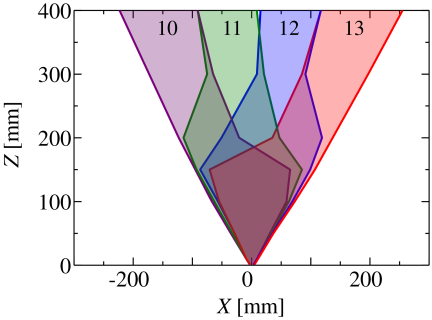
Fig. 9. The detection range of the \(XZ\)-axes calculated from the results of ToF sensor iii in Fig. 8.
3.3. \(X\)–\(Z\) Characteristics of Prototype Sensor
The experimental setup shown in Fig. 4 was used to evaluate the detection range of the prototype sensor along the \(X\)–\(Z\) plane. The object was a GND with a sheet of white paper attached to its surface. The object measured \({30 \times 190}\) mm, with a thickness of 1.6 mm. The robot arm, force gauge, and the side surface of the object did not affect the measurements. The center position of the sensor-object overlap was defined as \({X = 0}\) mm, and the position at which the sensor and object were in contact was defined as \({Z = 0}\) mm. The object was moved along the \(X\)-axis in 2 mm increments within a range of \(\pm\)350 mm and positioned along the \(Z\)-axis between 0 mm and 400 mm. Fig. 8 shows the experimental results. Fig. 8(a) shows the distance \(D\) measured using zone 11 of ToF sensor iii in the prototype, Fig. 8(b) shows \(D\) measured using zone 12 of ToF sensor iii, Fig. 8(c) shows the variation in capacitance (\({\Delta C}\)) measured by the prototype sensor, and Fig. 8(d) shows an enlarged view of Fig. 8(c). In Figs. 8(c) and (d), \({\Delta C}\) is not shown for distances greater than 200 mm because the variation was insufficient in that range. As shown in Figs. 8(a) and (b), the detectable range along the \(X\)-axis increased as the \(Z\)-axis distance increased owing to the wider spread of the emitted infrared light. In Figs. 8(c) and (d), \({\Delta C}\) increased as the object approached the sensor and as the overlap area between the object and sensor increased. Fig. 9 shows the detection range of the ToF sensor calculated from the results in Figs. 8(a) and (b) and zones 10–13. When an object was positioned more than 300 mm away, the position could be detected in each zone based on the alignment of the object. However, at shorter distances, the detected points within the measurement range were not clearly separated, making it difficult to determine the detailed position of the object even though its distance could still be detected. The FoV of the sensor was approximately 60°, which is consistent with the specifications. Similarly, Fig. 10 shows the detection ranges of ToF sensors i–iv calculated from Figs. 8(a) and (b), as well as the detection range of the self-capacitance sensor calculated from Fig. 8(c). ToF sensors provide a wide detection range but tend to exhibit blind spots near the sensor surface owing to the emission angle. In contrast, the self-capacitance sensor had a shorter detection range but almost no blind spots on the electrode surface. These results indicate that the proposed hybrid sensor, which combines ToF and self-capacitance sensing, can detect objects across a wide non-contact range with minimal blind spots on the sensor surface.
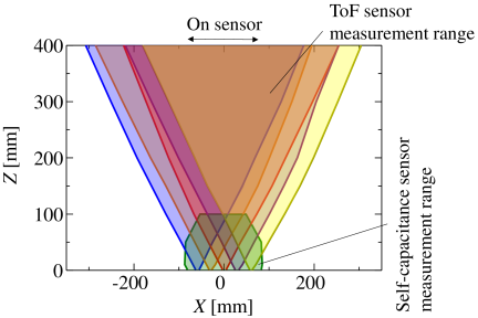
Fig. 10. The detection range of the \(XZ\)-axes calculated from the results of the ToF sensor and self-capacitance sensor in Fig. 8.
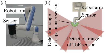
Fig. 11. The prototype sensor mounted on a robot arm and an image of the detection range based on the \(XZ\)-axes detection range in Fig. 10.
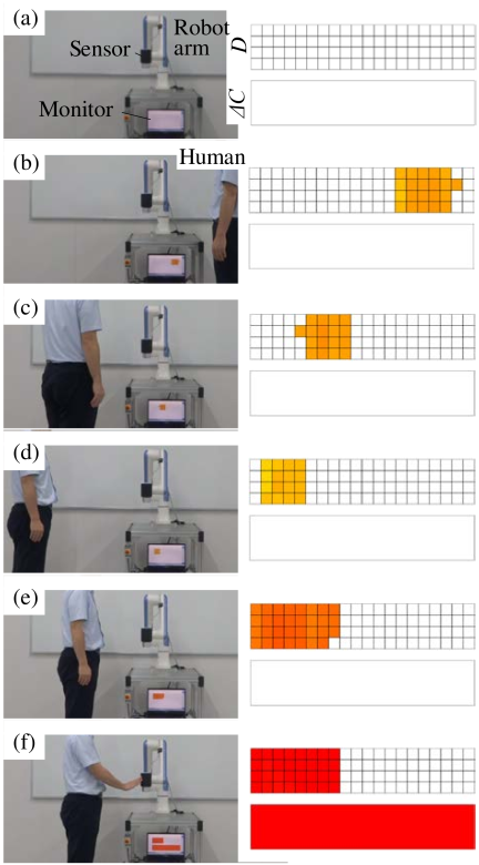
Fig. 12. Experimental results using sensors mounted on a robot. The object is a human, and the ToF sensor and self-sensor can measure proximity and contact status, respectively.
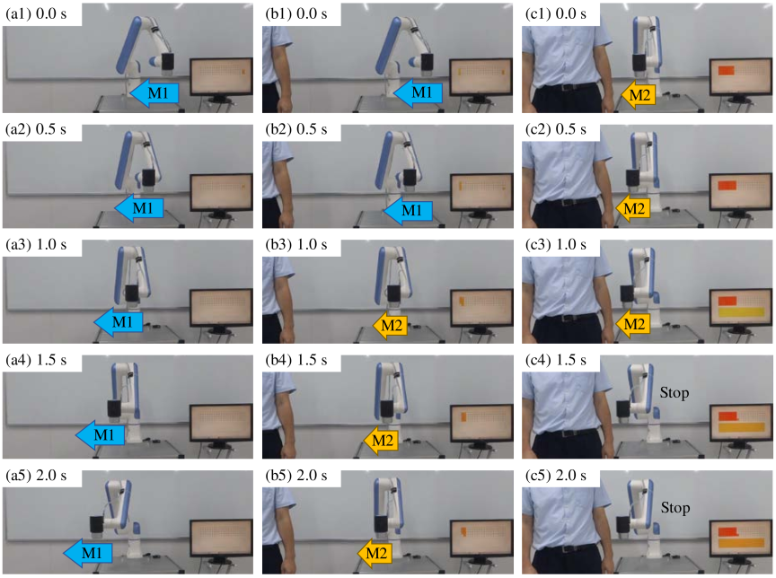
Fig. 13. Measurement and control results when the prototype sensor is attached to the robot arm. When an object is far away, the robot moves at normal speed (M1). When the robot approaches the object, the robot slows down (M2). When the robot approaches the object at 100 mm or less, the robot stops.
3.4. Measurement of the Prototype on a Robot Arm
The performance of the prototype sensor mounted on the robotic arm was evaluated. As shown in Fig. 11(a), the sensor was attached to a semi-cylindrical structure with an outer diameter of 76 mm to be installed at the tip of the robot arm. Consequently, the ToF sensors were arranged at intervals of approximately 45°. Fig. 11(b) shows the layout of each ToF sensor and the self-capacitance sensing area. This configuration allowed wide-area detection at the robot tip with minimal blind spots.
Figure 12 shows the experimental setup and results. The object was human. The upper in Fig. 12 shows the distance \(D\) measured by each ToF sensor, while the lower shows the variation in capacitance (\({\Delta C}\)) measured by the self-capacitance sensor. Fig. 12(a) corresponds to a condition in which the object is sufficiently distant from the sensor and no detection is observed. Figs. 12(b)–(e) show the approach of a human, and Fig. 12(f) shows the hand touching the sensor surface. The results show that the surrounding environment near the robot arm can be detected in a non-contact manner using ToF sensors and that contact with the object can be detected by the self-capacitance sensor.
3.5. Robot Operation Using Measurement Results
A prototype sensor mounted on the robot arm was used to control the robot based on the measurement data. In a previous study, a control method for a robot using a ToF, self-capacitance proximity, and contact sensors was proposed 18. A similar control scheme was applied to the proposed sensor, which integrated multiple ToF sensors with self-capacitance sensing. The purpose of this sensor system is to improve both the safety and operability of cobots that share the same workspace as humans, without requiring physical safety fences.
In this study, when the ToF sensor detected an object within 400 mm, the speed of the robot decreased (M2). The operating distance of M2 can be extended accordingly because the specified detection range of the VL53L7CX is 3,500 mm. Furthermore, when the detection distance of the ToF sensor was less than 100 mm or when the self-capacitance sensor detected an object in a non-contact manner, the robot stopped for safety. These control rules contribute to improving robot safety and operational efficiency.
Figure 13 shows the experimental setup and control results. The arrows indicate the direction of movement of the robot arm. A human was used as the object. The results were displayed on a monitor, as shown in Fig. 12. As shown in Fig. 13(a), when no object was present and the sensor detected nothing, the robot operated at normal speed (M1). When an object was present around the sensor and was detected, the robot moved at a reduced speed (M2), as shown in Fig. 13(b). When the detection distance of the ToF sensor became less than 100 mm or when the variation in capacitance (\({\Delta C}\)) exceeded 5\(\sigma\), the robot stopped to ensure safety, as shown in Fig. 13(c4). When all the ToF sensors detected distances greater than 100 mm and no object was detected by the self-capacitance sensor, the robot resumed operation. Furthermore, when all ToF sensors detected distances greater than 400 mm, the robot returned to its normal operating speed. These results demonstrate that the real-time control of the robot arm can be achieved using the measurements provided by the proposed sensor system. In this study, a simple control strategy was implemented to decelerate and stop the robot based on the distance measurements from the ToF sensor. However, the multi-zone ToF sensor allowed the acquisition of object positions, which could allow more advanced control of the robot arm based on the detected positions.
4. Conclusion
In this study, we proposed a multi-zone ToF sensor, self-capacitance proximity, and contact sensor for implementation on non-driven parts near the joint sections of cobots. The proposed sensor integrated multiple multi-zone ToF sensors onto a large electrode used for self-capacitance measurements. The prototype sensor, designed for installation at the tip of a robot arm, consisted of one self-capacitance electrode capable of detecting both non-contact and contact states and five multi-zone ToF sensors for distance measurement. The configuration was modified based on the mounting surface of the robot. Experimental evaluations were conducted to verify proximity sensing, contact detection, and \(X\)–\(Z\) detection ranges. The results demonstrated that seamless measurements from non-contact to contact conditions can be achieved. Furthermore, when mounted on a robot arm, the prototype sensor successfully detected the proximity and contact around the moving arm and allowed real-time control of the robot based on the measured data. These results confirm the effectiveness of the proposed sensor system. Therefore, multi-zone ToF, self-capacitance proximity, and contact sensors with multiple ToF sensors are considered promising approaches for improving the safety of cobots operating in shared workspaces.
Acknowledgments
This study was supported by the JSPS KAKENHI Grant Number 25K07688.
- [1] F. Flacco, T. Kröger, A. De Luca, and O. Khatib, “A depth space approach to human-robot collision avoidance,” 2012 IEEE Int. Conf. on Robotics and Automation, pp. 338-345, 2012. https://doi.org/10.1109/ICRA.2012.6225245
- [2] A. Latif, A. Mughall, M. H. D. Khan, and M. D. Khan, “A safety-enhancing framework based on collaborative robots (CoBot) for Industry 4.0,” 2024 Int. Conf. on Engineering & Computing Technologies (ICECT), 2024. https://doi.org/10.1109/ICECT61618.2024.10581298
- [3] P. Chemweno and R.-J. Torn, “Innovative safety zoning for collaborative robots utilizing Kinect and LiDAR sensory approaches,” Procedia CIRP, Vol.106, pp. 209-214, 2022. https://doi.org/10.1016/j.procir.2022.02.180
- [4] A. Schmitz et al., “Methods and technologies for the implementation of large-scale robot tactile sensors,” IEEE Trans. on Robotics, Vol.27, No.3, pp. 389-400, 2011. https://doi.org/10.1109/TRO.2011.2132930
- [5] T. Mukai, S. Hirano, H. Nakashima, Y. Sakaida, and S. Guo, “Realization and safety measures of patient transfer by nursing-care assistant robot RIBA with tactile sensors,” J. Robot. Mechatron., Vol.23, No.3, pp. 360-369, 2011. https://doi.org/10.20965/jrm.2011.p0360
- [6] K. Sato, L. Canete, and T. Takahashi, “Development of a spray-coated tactile sensor – Prototype and modeling of 2D sensor on cylindrical surface –,” J. Robot. Mechatron., Vol.31, No.6, pp. 882-893, 2019. https://doi.org/10.20965/jrm.2019.p0882
- [7] M. Muroyama, H. Hirano, C. Shao, and S. Tanaka, “Development of a real-time force and temperature sensing system with MEMS-LSI integrated tactile sensors for next-generation robots,” J. Robot. Mechatron., Vol.32, No.2, pp. 323-332, 2020. https://doi.org/10.20965/jrm.2020.p0323
- [8] H. Alirezaei, A. Nagakubo, and Y. Kuniyoshi, “A tactile distribution sensor which enables stable measurement under high and dynamic stretch,” 2009 IEEE Symp. on 3D User Interfaces, pp. 87-93, 2009. https://doi.org/10.1109/3DUI.2009.4811210
- [9] T. Schlegl, T. Kröger, A. Gaschler, O. Khatib, and H. Zangl, “Virtual whiskers—Highly responsive robot collision avoidance,” 2013 IEEE/RSJ Int. Conf. on Intelligent Robots and Systems, pp. 5373-5379, 2013. https://doi.org/10.1109/IROS.2013.6697134
- [10] H. Hasegawa, Y. Suzuki, A. Ming, M. Ishikawa, and M. Shimojo, “Robot hand whose fingertip covered with net-shape proximity sensor – Moving object tracking using proximity sensing –,” J. Robot. Mechatron., Vol.23, No.3, pp. 328-337, 2011. https://doi.org/10.20965/jrm.2011.p0328
- [11] T. D. Nguyen et al., “Skin-type proximity sensor by using the change of electromagnetic field,” IEEE Trans. on Industrial Electronics, Vol.68, No.3, pp. 2379-2388, 2021. https://doi.org/10.1109/TIE.2020.2975503
- [12] S. Tsuji and T. Kohama, “Proximity skin sensor using time-of-flight sensor for human collaborative robot,” IEEE Sensors J., Vol.19, No.14, pp. 5859-5864, 2019. https://doi.org/10.1109/JSEN.2019.2905848
- [13] H.-K. Lee, S.-I. Chang, and E. Yoon, “Dual-mode capacitive proximity sensor for robot application: Implementation of tactile and proximity sensing capability on a single polymer platform using shared electrodes,” IEEE Sensors J., Vol.9, No.12, pp. 1748-1755, 2009. https://doi.org/10.1109/JSEN.2009.2030660
- [14] G. Cheng et al., “A comprehensive realization of robot skin: Sensors, sensing, control, and applications,” Proc. of the IEEE, Vol.107, No.10, pp. 2034-2051, 2019. https://doi.org/10.1109/JPROC.2019.2933348
- [15] J. Liang et al., “Soft sensitive skin for safety control of a nursing robot using proximity and tactile sensors,” IEEE Sensors J., Vol.20, No.7, pp. 3822-3830, 2020. https://doi.org/10.1109/JSEN.2019.2959311
- [16] F. Giovinazzo et al., “From CySkin to ProxySKIN: Design, implementation and testing of a multi-modal robotic skin for human–robot interaction,” Sensors, Vol.24, No.4, Article No.1334, 2024. https://doi.org/10.3390/s24041334
- [17] Y. Ding, F. Wilhelm, L. Faulhammer, and U. Thomas, “With proximity servoing towards safe human-robot-interaction,” 2019 IEEE/RSJ Int. Conf. on Intelligent Robots and Systems, pp. 4907-4912, 2019. https://doi.org/10.1109/IROS40897.2019.8968438
- [18] S. Tsuji and T. Kohama, “Self-capacitance proximity and tactile skin sensor with shock-absorbing structure for a collaborative robot,” IEEE Sensors J., Vol.20, No.24, pp. 15075-15084, 2020. https://doi.org/10.1109/JSEN.2020.3011701
- [19] S. Tsuji and T. Kohama, “Proximity and contact sensor for human cooperative robot by combining time-of-flight and self-capacitance sensors,” IEEE Sensors J., Vol.20, No.10, pp. 5519-5526, 2020. https://doi.org/10.1109/JSEN.2020.2969653
- [20] S. Tsuji, “Wrap-around string-like ToF and self-capacitance combined sensor for robots,” IEEJ Trans. on Electrical and Electronic Engineering, Vol.20, No.5, pp. 688-695, 2025. https://doi.org/10.1002/tee.24232
- [a] Universal Robots. https://www.universal-robots.com/ [Accessed November 10, 2025]
- [b] STMicroelectronics, VL53L7CX. https://www.st.com/en/imaging-and-photonics-solutions/vl53l7cx.html [Accessed November 10, 2025]
This article is published under a Creative Commons Attribution-NoDerivatives 4.0 Internationa License.