
Paper:
Dynamic and Simultaneous Measurement of Force, Temperature, and Light Using Miniature Tactile Sensor
Mizuki Takahashi, Mako Nakamura, Takashi Abe, and Masayuki Sohgawa
Niigata University
8050 Ikarashi 2-no-cho, Nishi-ku, Niigata, Niigata 950-2181, Japan

In this study, a MEMS tactile sensor was designed and fabricated, with the aim of achieving integrated measurement of object contact, thermal, and proximity sensation. This sensor integrates a Si photoresistor for light detection, a microcantilever with a NiCr strain gauge for force detection, and an Au resistance thermometer detector with a heater for temperature detection. Furthermore, since both the strain gauge and the photoresistor exhibit temperature dependency, temperature compensation was applied to the measured data. Thus, it was demonstrated that a single sensor can dynamically and simultaneously measure different modalities: object contact force, thermal, and proximity sensation. Sensors equipped with both tactile and proximity capabilities are expected to enable accurate manipulation and control of grasping force.
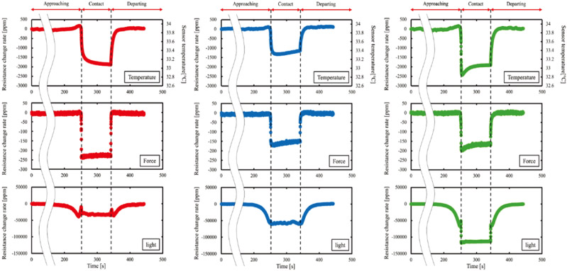
Simultaneous multimodal measurement targeting (a) Al, (b) POM, and (c) PDMS
1. Introduction
The recent decline in working-age population in many developed countries is severe owing to the decrease in population. The reduction in the number of workers and the aging of the labor force pose significant challenges especially in the agricultural sector. Although IoT technology is applied across many fields and is expected to resolve problems associated with the declining birthrate and aging population, many issues remain to be addressed in the agricultural sector. The industrial robots used in the manufacturing sector handle materials with defined specifications, or objects with high rigidity. However, agricultural products are diverse in shape, and soft vegetables and fruits are easily damaged, thus requiring precise control of the gripping force 1. To enable autonomous agricultural robots to handle delicate crops, such as strawberries and tomatoes, without causing damage, integrated sensors must satisfy certain specific functional requirements. A force resolution of less than 0.1 N is required to detect the initial contact and to precisely adjust the gripping force 2. Furthermore, a rapid sensor response is essential for achieving real-time feedback control to prevent slippage during the movement of the robotic hand 3,4. Humans can hold soft objects without crushing them by integrating and processing information obtained through vision and touch. Robots require sensors that mimic both human vision and touch. In the current implementation examples, images obtained from cameras are processed using AI 5. However, challenges still persist, such as measurement errors and camera-blind spots, which prevent the accurate capture of the exact moment of object grasping 6. The integration of force, temperature, and light sensing is crucial to overcome these challenges in agricultural environments. In this context, the light sensor functions as a proximity sensor to detect the distance to the target and its surface conditions before contact, thereby allowing the robot to decelerate and avoid high-impact collisions that could lead to bruising. Upon contact, the force sensor enables precise grasping force control. Simultaneously, the integrated heater and resistance thermometer detector (RTD) allow active thermal sensing to identify the thermal properties of the object. This capability is essential for distinguishing between the target crop and environmental obstacles, such as metal-supporting poles or plastic leaves, which may have similar visual appearances but vastly different thermal conductivities. This multimodal approach allows the robot to reliably identify and grasp crops even in fluctuating outdoor light or cluttered environments, where systems that are based on vision alone may fail. This study aims to realize such a multifunctional capability within a single miniature microelectromechanical system (MEMS) chip to provide a robust sensing solution for small robotic grippers. Prior works include commercially available sensors that combine any two of the following detection modalities: tactile, thermal, and proximity sensing 7,8,9. However, these challenges are related to high production costs and difficulty in miniaturization.
Therefore, tactile sensors have been miniaturized using MEMS technology 10,11. However, only a few studies have integrated multiple detection modalities. Consequently, we first attempted to combine force measurement and proximity sensing by integrating a light detection element using MEMS technology 12. Subsequently, we integrated a temperature detection element to enable the combined measurement of thermal sensation 13,14,15. This sensor is compact (chip size: 5 mm \(\times\) 5 mm) and is expected to achieve low cost through mass production.
In our previous studies, the combined measurement of force, light, and temperature was achieved using the same sensor. However, a drawback was the decrease in sensitivity and stability owing to the use of identical sensing elements for measuring temperature and light 16. Therefore, we fabricated the sensing elements separately. Furthermore, for light and temperature measurements, we employed DC resistance measurements instead of impedance measurement 17,18. By implementing these methods, we achieved improvements in sensitivity and stability for both light detection and thermal sensation detection. Previous studies do not mention attempts made to integrate the three types of sensing elements, specifically the force sensing element and separately fabricated DC resistance-measurable temperature and light sensing elements, onto a single chip. In this study, we re-examined the layout and fabrication process of the light and thermal sensing elements and, by integrating them along with a force-sensing element, succeeded in performing simultaneous multimodal measurements of tactile, thermal, and proximity sensations at the same location. It was demonstrated that the contact state and characteristics of a contact object can be analyzed dynamically and in real time from the mechanical, thermal, and optical perspectives.
2. Tactile Sensor for Multi-Modal Measurement and Detection Principle
The detection principles for each sensing element are described below.
Regarding the principle of force detection, applying an external force to polydimethylsiloxane (PDMS) that encapsulates the cantilever causes the PDMS to deform. This deformation results in cantilever deflection. The resulting surface strain due to deflection was measured using a strain gauge. Therefore, an external force can be detected by measuring the strain gauge resistance.
Regarding the principle of thermal sensation detection, when there is a temperature difference between the sensor and the object, heat flow is generated upon contact. This causes a change in the temperature of the sensor, which is measured using the temperature dependence of electrical conductivity. Differences in the thermal conductivity and heat capacity of the objects which are in contact cause variations in the resulting change in the sensor temperature, making it possible to distinguish between perceived thermal sensations.
According to the principle of light detection, when light is incident on an object, the resistance changes because of the photoconductive effect. This change in the resistance enables the detection of light.
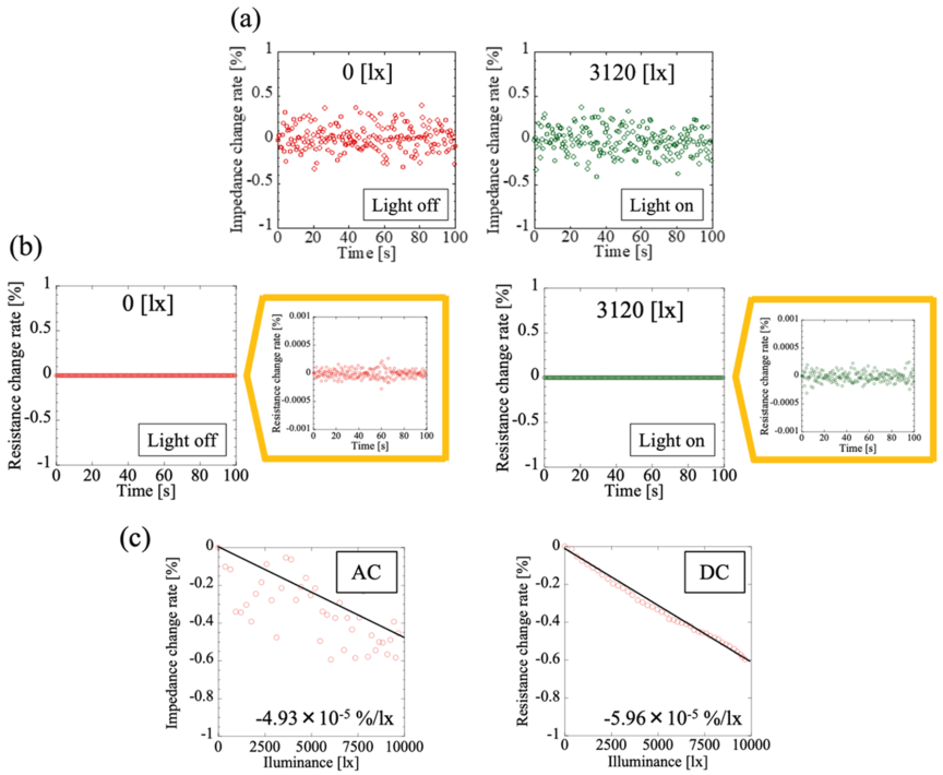
Fig. 1. The rate of (a) impedance change and (b) DC resistance change when the LED is off and when it is illuminated at 3120 lx, and (c) change in impedance and DC resistance with respect to illuminance.
In previous studies, the conductivity, contingent on light and temperature, was measured through the change in the AC impedance of a circuit, facilitated by the insulating and active layers beneath the wiring. This method was prioritized because of its simplicity and ease of fabrication. However, this method suffers from issues related to parasitic capacitance and electromagnetic noise due to measurement at high frequencies. Furthermore, because the Si active layer retains its sensitivity to both temperature and light, it is difficult to separate the responses. As a countermeasure, we implemented DC resistance measurement by wiring the electrodes directly onto the Si layer for light detection and temperature measurements were made using the RTD of Au. Fig. 1 demonstrates the technical justification for adopting the DC measurement by comparing its stability with that of the conventional AC method. In this evaluation, the three times the standard deviation (\(3\sigma\)) value of the output signal was calculated over a fixed period as an index of response stability. For the impedance measurement, the \(3\sigma\) value was 0.43% for both the LED-off and LED-on states. In contrast, the DC resistance measurement achieved a significantly lower \(3\sigma\) value of 0.00022% in the unlit state and 0.00025% in the lit state. To validate the signal-to-noise ratio (SNR) comparison, it is crucial to consider the effective signal magnitude. It was confirmed that the fractional resistance change, \({\Delta R}/{R}\), under a constant light intensity, remained essentially unchanged regardless of the measurement method (AC or DC). For example, at an identical light intensity of 3120 lx, the response magnitudes of the two methods were comparable. Consequently, as shown in Fig. 1, the DC resistance measurement achieved a noise floor which was approximately 2,000 times lower than that of the impedance measurement while maintaining the same signal magnitude. This results in a significantly higher SNR, enabling the detection of minute resistance changes without being obscured by electrical noise.
Therefore, a Si photoresistor that uses DC resistance measurements for light detection was adopted. For thermal sensation detection, an Au RTD and a heater were integrated into the chip. This resulted in reduced noise and enabled stable measurements compared to impedance change measurements 18. Nakamura et al. fabricated a sensor that integrated a light-sensing element using a Si photoresistor and a thermal-sensing element using an Au RTD mounted on a single chip, and it could measure heat and light simultaneously and stably. However, they did not integrate a force-sensing element 19. Therefore, in this study, we designed a chip and its fabrication process, which integrates a force-sensing element (cantilever) in addition to the photoresistor and RTD. Fig. 2 shows the chip of the MEMS tactile sensor designed in this study. For light measurements, electrodes were fabricated to connect with the Si layer to form a photoresistor. For thermal sensation detection, a temperature resistor and heater were integrated into the chip. The on-chip heater allowed the sensor to reach thermal equilibrium faster than in the conventional method using an external heater, resulting in improved stability 18.
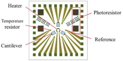
Fig. 2. MEMS tactile sensor with improved resistor.
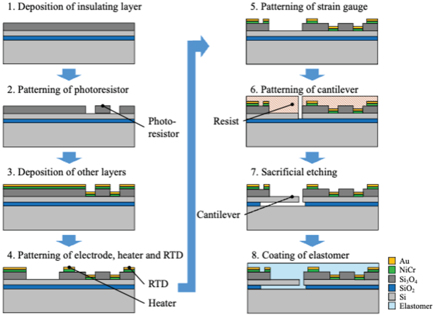
Fig. 3. Schematic diagram of the MEMS tactile sensor fabrication process.
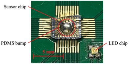
Fig. 4. MEMS tactile sensor mounted on PCB.
Figure 3 illustrates the sensor fabrication process. The sensor used in this study is fabricated using MEMS processing on an SOI wafer substrate. First, an insulating layer of Si\(_3\)N\(_4\) was deposited on an SOI wafer by RF sputtering. Subsequently, photolithography and etching were used to remove Si\(_3\)N\(_4\) from the areas designated as the Si photoresistor electrodes. Next, NiCr and Au thin films were deposited using RF sputtering, followed by patterning of the interconnects, strain gauge, and heater of NiCr and the interconnects of Au using photolithography and etching. The cantilevers were patterned in the same manner as described previously. The wafer was then separated into chips by dicing and a cantilever structure was formed through sacrificial layer etching. Finally, the chip was cleaned with deionized water, immersed in highly volatile ethanol to prevent stiction, and vacuum dried. Fig. 4 shows the sensor after implementation. The sensor chip was fixed onto a printed circuit board (PCB) using an epoxy adhesive and electrically connected via Au wire bonding. The MEMS structure and the bonding wires on the chip were encapsulated using spin-coated PDMS, and a hemispherical PDMS bump (\(\varphi\)2) was attached to the center of the chip. Additionally, an LED chip (1.3 mm \(\times\) 2.0 mm) was implemented on the PCB, for light measurement.
3. Multi-Modal Measurement of Force, Temperature, and Light Using a Tactile Sensor
3.1. Response Evaluation of the Temperature, Force, and Light
To perform combined measurements in a multimodal system, the response characteristics of each element to temperature, light, and force must be clarified. Because the strain gauge and photoresistor are also expected to exhibit temperature dependence, their respective temperature characteristics are measured.
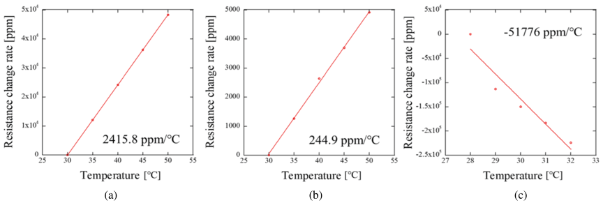
Fig. 5. Temperature dependence of (a) the Au RTD, (b) the NiCr strain gauge, and (c) the Si photoresistor.
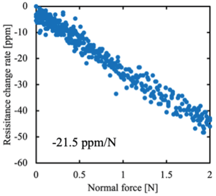
Fig. 6. Force dependence of the NiCr strain gauge.
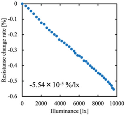
Fig. 7. Light dependence of the Si photoresistor.
Figure 5 shows the temperature dependence of (a) the Au RTD, (b) the NiCr strain gauge, and (c) the Si photoresistor. Due to the significant temperature-induced variation in the photoresistor, its resistance change was measured while the temperature was increased from 28°C to 31°C in increments of 1°C. Each sensing element exhibits a linear change in resistance with respect to temperature. For metals such as Au and NiCr, the resistance increases because of the enhanced scattering probability of free electrons caused by the increased atomic vibrations that accompany the temperature increase. Conversely, for semiconductors such as Si, the resistance decreases because the increase in carrier density accompanying the temperature increase outweighs the increase in electron scattering. The temperature coefficient of resistance (TCR) was determined to be 2415.8 ppm/°C for the Au RTD, 244.9 ppm/°C for the NiCr strain gauge, and \(-\)51776 ppm/°C for the Si photoresistor.
Figure 6 shows the force characteristics of the NiCr strain gauge. When a force is applied to the PDMS bump, the incompressibility of the PDMS causes it to be compressed vertically, resulting in horizontal expansion of the material. This horizontal expansion increases the deflection of the cantilever, inducing a compressive strain on its surface. Consequently, the resistance of the strain gauge decreases linearly with respect to the applied force. The force dependence of the NiCr strain gauge was determined to be \(-\)21.5 ppm/N.
Figure 7 shows the light characteristics of the Si photoresistor. When light is incident on a photoresistor, its resistance decreases linearly because of the photoconductive effect. The light dependence of the Si photoresistor was determined to be \(-5.54\times 10^{-5}\)%/lx.
3.2. Summary of Simultaneous Multi-Modal Measurement
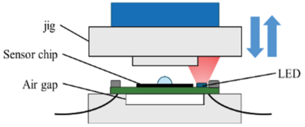
Fig. 8. Schematic diagram of the multimodal measurement.
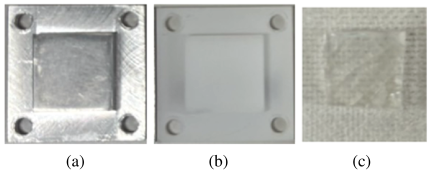
Fig. 9. Contact objects used for multimodal measurement (a) Al, (b) POM, and (c) PDMS.
Figure 8 shows the experimental setup for evaluating the response of the multimodal tactile sensor used in this study. The resistance of each sensing element is measured using a multimeter. A motorized stage was used to move the contact object along the \(z\)-axis. A six-axis force sensor was attached to the upper stage for contact force measurements for stage control. In this study, the contact object was mounted on the upper stage and the tactile sensor mounted on the PCB was fixed to the lower stage. An air gap is provided in the lower stage to mitigate the heat flow transferred when the sensor is heated. In this multimodal measurement, the resistance values of the strain gauge, photoresistor, and RTD were measured simultaneously.
The measurement procedure is outlined as follows. The \(z\)-stage was moved toward the sensor at a speed of 0.5 mm/s, starting from a position 50 mm away from the contact object to the top of the sensor’s PDMS bump. The normal force during contact was set to 10 N (with an error of \(\pm 10\)%). During measurement, the heater was heated by applying 10 V, and the sensor temperature stabilized at approximately 33.9°C before contact. The LED is illuminated by applying voltage of 2 V. The sensor was held in contact for 90 s to maintain a constant force of 10 N and then returned to its original position at the same speed. It should be noted that the measurements are conducted inside a dark box to prevent the influence of ambient light. Fig. 9 shows several contact objects, including Al, polyoxymethylene (POM), and PDMS, with different thermal, mechanical, and optical characteristics used for multimodal measurements. The Al and POM have holes drilled in their four corners for fixed mounting on a three-axis motorized stage using screws. Furthermore, PDMS was adhered to the surface of Al.
3.3. Results of Simultaneous Multi-Modal Measurement
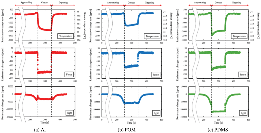
Fig. 10. Simultaneous multimodal measurement targeting (a) Al, (b) POM, and (c) PDMS.
Figure 10 shows the change in resistance of the Au RTD, NiCr strain gauge of the cantilever, and Si photoresistor for each contact object as a result of the multimodal measurement. The responses of the force and light sensors shown in Fig. 10 are the results obtained after applying temperature compensation to decouple the thermal influence from each sensing modality. The rate of change of temperature with respect to time \({\Delta T}/{T}\) is shown in Eq. \(\eqref{eq:1}\):
4. Discussion
As shown in the temperature measurement graphs, the RTD resistance decreases upon contact and returned to its initial value when the two surfaces are separated. Because Al has a higher thermal conductivity than POM, the decrease in resistance is greater. Although PDMS has a thermal conductivity similar to that of POM, it exhibits a greater decrease in resistance, which is considered to be related to the increase in contact area caused by the difference in hardness and heat transfer to the Al object on which the PDMS is adhered. Furthermore, in the case of POM and PDMS, the temperature initially decreases and then begins to increase. This is considered to be due to the fact that heat transfer is influenced not only by differences in thermal conductivity but also by density, specific heat capacity, and surface shape, or because convective heat transfer is obstructed by the presence of the object 16,18.
The force measurement graphs show that the resistance of the strain gauge decreased upon contact, demonstrating the application of force. Because of the temperature compensation, the strain gauge resistance after contact becomes nearly constant over time, correctly demonstrating the state in which the sensor is held stationary under a constant force. However, the magnitude of the change in resistance differed among the contact objects. Although the target load was set to 10 N, the actual applied loads monitored by the six-axis force sensor showed slight variations within a tolerance of \(\pm 10\)%, specifically 10.67 N for Al, 10.15 N for POM, and 10.24 N for PDMS at 50 s after contact. The proposed sensor was sensitive enough to detect these 0.1 N-level differences as distinct fractional resistance changes. Additionally, these differences are influenced by the variation in the force dependence of the strain gauge, as shown in Fig. 6. Furthermore, in the case of the PDMS, the resistance gradually increases after initially decreasing. This is attributed to the relaxation in stress caused by the viscoelasticity of PDMS, which leads to redistribution of the internal stress after the initial contact.
The light measurement graphs show that, as the object approaches, the resistance of the photoresistor decreases owing to an increase in the reflected light from the contact object. Although the specific surface roughness of the test samples was not measured in this study, the materials were selected to represent the distinct optical reflection properties as a baseline evaluation. The magnitude of the reflected light varies depending on the material properties of the target; for materials with large surface roughness, such as standard machined POM, diffuse reflection increases the total amount of light incident on the photoresistor. In contrast, for glossy materials such as commercially available smooth Al plates, specular reflection is dominant, which results in a large reflection only at specific angles, potentially reducing the overall amount of light incident on the sensor compared with diffusing surfaces. Furthermore, internal reflection within the PDMS is a critical factor in the change in resistance when a force is applied. The light incident on the sensor includes not only reflections from the contact surface, but also those from the side and top surfaces, including the adhesion interface between the PDMS and the Al frame. This internal optical network is sensitive to the geometric changes of the sensor body. The application of force upon contact compresses the elastomeric body and pushes the PDMS closer to these reflective surfaces, consequently decreasing the optical path distance and increasing the amount of incident light captured using a photoresistor. After the contact was established, the resistance of the photoresistor became nearly constant. This stability occurs because the relative distance between the sensor and the object remains fixed during the stable grasping phase. Moreover, by applying the described temperature compensation, the influence of the heat generated by the integrated heater or environment is effectively canceled, allowing the sensor to provide a steady signal that clearly indicates the onset of a stable grasp and ensures the decoupling of thermal and optical stimuli.
5. Conclusions
This study successfully designed and fabricated a multimodal MEMS tactile sensor capable of dynamic and simultaneous measurement of force, thermal sensation, and light, satisfying the requirements for delicate agricultural robotic tasks, such as a force resolution of 0.1 N and rapid response. For light detection, the implementation of a Si photoresistor using DC resistance measurement effectively minimized electromagnetic noise, achieving an exceptionally high \(3\sigma\) stability of 0.00022% compared to conventional AC-based methods. For thermal sensing, the on-chip integration of a Au RTD and a heater significantly improved both the response speed and measurement stability. Furthermore, by utilizing the real-time RTD values as a reference for temperature compensation, the thermal influences on the strain gauge and photoresistor were successfully decoupled, allowing for independent extraction of each modality within a compact 5 mm \(\times\) 5 mm footprint.
The developed measurement system operates at a sampling rate of 0.1 s, providing a temporal resolution of 10 Hz. In this study, the term dynamic refers to the capability of real-time sequential monitoring of grasping phases from the approaching phase to the stable contact phase. At typical approach speeds for agricultural grippers (10–50 mm/s), this resolution enables data acquisition for every 1–5 mm of movement, which is sufficient to perform feedback control, such as decelerating the gripper before contact to minimize impact or adjusting the grasping force to prevent slip 20. Therefore, the developed sensor and its measurement system demonstrated adequate responsiveness and a superior balance between miniaturization and measurement reliability for the intended agricultural applications.
Acknowledgments
This study was supported by JSPS KAKENHI Grant Number JP23K22713.
- [1] J. Ao, Y. Song, Q. Li, H. Zeng, and T. Xu, “End-effectors for fruit and vegetable harvesting robots: A review of key technologies, challenges, and future prospects,” Agronomy, Vol.15, No.11, Article No.2650, 2025. https://doi.org/10.3390/agronomy15112650
- [2] Z. Hou et al., “Soft grasping mechanism of human fingers for tomato-picking bionic robots,” Computers and Electronics in Agriculture, Vol.182, Article No.106010, 2021. https://doi.org/10.1016/j.compag.2021.106010
- [3] W. Mandil et al., “Tactile-sensing technologies: Trends, challenges and outlook in agri-food manipulation,” Sensors, Vol.23, No.17, Article No.7362, 2023. https://doi.org/10.3390/s23177362
- [4] G. Laudante et al., “A multi-modal sensing system for human-robot interaction through tactile and proximity data,” Front. Robot. AI, Vol.12, Article No.1581154, 2025. https://doi.org/10.3389/frobt.2025.1581154
- [5] T. Fukao, “Automation and robotization of farming operations (special feature: the future of food),” J. of the Japan Society of Mechanical Engineers, Vol.127, No.1273, pp. 7-10, 2024 (in Japanese). https://doi.org/10.1299/jsmemag.127.1273_7
- [6] S. Ye, K. Suzuki, Y. Suzuki, M. Ishikawa, and M. Shimojo, “Robust robotic grasping using IR net-structure proximity sensor to handle objects with unknown position and attitude,” Proc. of the 2013 IEEE Int. Conf. on Robotics and Automation, pp. 3271-3278, 2013. https://doi.org/10.1109/ICRA.2013.6631033
- [7] T. Yamamoto, N. Wettels, J. A. Fishel, C. Lin, and G. E. Loeb, “BioTac—A biomimetic tactile sensor,” J. of the Robotics Society of Japan, Vol.30, No.5, pp. 496-498, 2012 (in Japanese). https://doi.org/10.7210/jrsj.30.496
- [8] S. Tsuchiya, Y. Suganuma, M. Muroyama, T. Nakayama, and Y. Nonomura, “Measurement of heat flow using a thermal-force sensor stick with a tactile neural network chip,” Electrical Engineering in Japan, Vol.139, No.8, pp. 258-264, 2012 (in Japanese). https://doi.org/10.1541/ieejsmas.139.258
- [9] Y. Mizoguchi, K. Tadakuma, H. Hasegawa, A. Ming, M. Ishikawa, and M. Shimojo, “Development of intelligent robot hand using proximity, contact and slip sensing,” Proc. of the 2007 IEEE Int. Conf. on Robotics and Automation, pp. 3087-3092, 2007. https://doi.org/10.1109/ROBOT.2007.363945
- [10] R. Kaneta, T. Hasegawa, T. Abe, and M. Sohgawa, “Sensitivity enhancement of MEMS tactile sensor by redesign of microcantilever and strain gauge,” 2021 IEEE SENSORS, 2021. https://doi.org/10.1109/SENSORS47087.2021.9639799
- [11] K. Takahashi, T. Abe, M. Okuyama, H. Noma, and M. Sohgawa, “Surface texture characterization using optical and tactile combined sensor,” Sens. Mater., Vol.30, No.5, pp. 1091-1101, 2018. https://doi.org/10.18494/SAM.2018.1786
- [12] S. Yokoyama, T. Kanashima, M. Okuyama, T. Abe, H. Noma, T. Higashi, and M. Sohgawa, “Proximity and tactile sensing using MEMS sensor with combined light and strain detection,” IEEJ Trans. on Sensors and Micromachines, Vol.134, No.7, pp. 229-234, 2014 (in Japanese). https://doi.org/10.1541/ieejsmas.134.229
- [13] M. Sohgawa, S. Nishimura, R. Okuno, T. Abe, and H. Noma, “Multifunctional tactile sensor using MEMS cantilevers,” Proc. of the 2014 Int. Nanoelectronics Conf. (INEC), pp. 317-318, 2014. https://doi.org/10.1109/INEC.2014.7460417
- [14] R. Araki, T. Abe, H. Noma, and M. Sohgawa, “Miniaturization and high-density arrangement of microcantilevers in proximity and tactile sensor for dexterous gripping control,” Micromachines, Vol.9, No.6, Article No.301, 2018, https://doi.org/10.3390/mi9060301
- [15] S. Ogawara, M. Sohgawa, and T. Abe, “Combined measurement of force, color, and temperature for skin diagnosis using MEMS tactile sensor,” Proc. of the JSME Annual Meeting, Vol.2020, Article No.J16312, 2020 (in Japanese). https://doi.org/10.1299/jsmemecj.2020.J16312
- [16] F. Sato et al., “Texture measurement for fabrics including warm/cool and fluffiness sensation by multimodal MEMS sensor,” 2017 19th Int. Conf. on Solid-State Sensors, Actuators and Microsystems (TRANSDUCERS), pp. 343-346, 2017. https://doi.org/10.1109/TRANSDUCERS.2017.7994058
- [17] H. Sato, “S/N ratio improvement of photodetection part in MEMS composite sensor for skin diagnosis,” Proc. of the JSME Hokuriku-Shinetsu Branch 2022 Joint Conf., 2022 (in Japanese).
- [18] N. Onda, T. Kozuka, T. Abe, M. Isshiki, S. Tomeno, and M. Sohgawa, “Fabrication of heater-integrated MEMS tactile sensor for evaluation of warm and cold sensation by touching glass,” Electrical Engineering in Japan, Vol.215, No.1, Article No.e23370, 2022. https://doi.org/10.1002/eej.23370
- [19] M. Nakamura, T. Abe, and M. Sohgawa, “Integration of light and temperature sensing elements for combined visual and tactile measurement of resin compounds,” IEEJ Trans. on Sensors and Micromachines, Vol.144, No.9, pp. 252-257, 2024 (in Japanese). https://doi.org/10.1541/ieejsmas.144.252
- [20] N. Kounalakis et al., “Development of a tomato harvesting robot: Peduncle recognition and approaching,” 2021 3rd Int. Congress on Human-Computer Interaction, Optimization and Robotic Applications (HORA), 2021. https://doi.org/10.1109/HORA52670.2021.9461281
This article is published under a Creative Commons Attribution-NoDerivatives 4.0 Internationa License.