
Paper:
Performance Evaluation of an Optical Tactile Force Sensor Using Transparent Flexible Resin
Masanori Goka and Yoshifumi Matsumoto
Department of Electrical and Electronic Engineering, Fukuyama University
1 Sanzo, Gakuen-cho, Fukuyama, Hiroshima 729-0292, Japan

This study aims to enhance tactile sensing for practical robotic applications by enabling the acquisition of dynamic contact information in optical tactile sensors. Conventional optical tactile sensors measure displacement and torque with high precision by detecting the deformation of transparent flexible resin using photoreflectors; however, they do not fully exploit information from minute vibrations or dynamic contact events. In this work, we propose a lightweight, low-cost, and robust optical tactile sensor capable of texture recognition and slippage detection without relying on acceleration sensors or piezoelectric elements, offering a simpler and more durable alternative to conventional high-definition camera-based approaches.
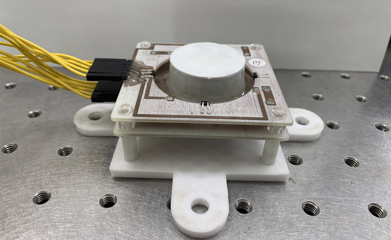
Prototype optical tactile force sensor
1. Introduction
In recent years, with the advancement of AI and IoT technologies, various types of robots—from industrial robots to service robots, and further to collaborative robots that operate in the same space as humans—have been proposed, and their social implementation has been rapidly progressing. These robots are expected to complement or replace human abilities and perform tasks quickly and with high accuracy in a wide range of fields, not only in manufacturing where labor-saving and automation are strongly required, but also in logistics, medical and welfare services, and daily-life support. In particular, for robots that work collaboratively with humans, realizing tactile feedback functions similar to those of the human hand is an important engineering challenge in order to achieve safe and flexible manipulation and grasping.
Conventional robotic hands have mainly relied on high-rigidity structures and motor control, but they have limitations in reproducing the flexibility and dexterity of the human hand. For this reason, together with the development of soft robotics, the development of high-function tactile sensors has been attracting attention. Many tactile sensors have been proposed that can measure static indentation and deformation with high accuracy, but there remains the challenge that they cannot sufficiently utilize information from dynamic contact or small vibrations. High-resolution image-based tactile sensors proposed to date can obtain deformation distributions; however, they have issues of complex structure, high cost, and limited durability, and thus their application to practical robotics is restricted. There also exist methods that add accelerometers or piezoelectric elements to detect vibration, but these approaches make the structure more complicated and hinder lightweight and low-cost design.
Furthermore, various approaches exist in tactile sensor research depending on the sensing principle used. The authors have previously developed magnetic tactile sensors that encapsulate magnetic material inside flexible resin and detect changes in the magnetic field due to deformation using magnetoresistive elements or inductors 1,2. These methods are small, structurally simple, and capable of measurement that makes use of the elasticity of the resin; however, they have limitations in operation due to the influence of external magnetic fields and geomagnetism.
On the other hand, image-based tactile sensors that observe the deformation of resin optically with high precision have developed significantly in recent years, and methods that obtain high-resolution deformation of the resin surface have been proposed 4,3. OmniTact captures multidirectional deformation of the gel simultaneously using multiple micro-cameras, achieving both a wide sensing range and high resolution, and demonstrating high performance in estimating contact angles of complex-shaped objects and in difficult insertion tasks 5. DIGIT has achieved miniaturization and improved manufacturing reproducibility as a vision-based tactile sensor, and has been shown to be effective for precise in-hand manipulation with multi-fingered hands 6. TacTip optically tracks marker points inside a flexible membrane, enabling recognition of edge shapes and textures while maintaining robustness 8,7,6. In the family of GelSight research, high-resolution 3D reconstruction of contact surfaces, detection of incipient slip, and estimation of contact force distribution have been realized, providing advanced tactile information required for robot manipulation 9,10,11,12.
However, these high-function optical tactile sensors require multiple cameras, special polymer materials, and high-intensity illumination in order to achieve high accuracy, resulting in complex structures and making the devices large and expensive. Moreover, issues remain for practical devices intended for long-term operation, such as the high frequency of replacement due to wear and deterioration of the gel surface, the large computational load associated with image processing, and low durability. In particular, the acquisition of dynamic tactile information—such as small vibrations at the moment of contact or early indications of the onset of slip—is susceptible to the influence of material characteristics and delays in the processing system, leaving challenges in terms of stability and reliability. From these points, there is a need for a new approach to tactile sensors that are low-cost, compact, and lightweight, while being capable of acquiring both static and dynamic tactile information, and that also provide high implementability and durability.
Based on this background, we have proposed an optical tactile sensor that uses transparent flexible resin and photoreflectors, and we have previously presented its capability to measure three-axis displacement and force, as well as rotational displacement and torque in the \(XY\) plane 13,14,15. This device has the features of requiring few wires, being low-cost and robust, and exhibiting small drift during long-term operation. However, previous implementations were mainly limited to measuring static contact states, and there were limitations in utilizing dynamic contact information such as slip sensation, property recognition based on micro-vibrations, and other dynamic features.
In this study, in order to address these issues, we improve the optical system (flattening the photoreflector lens and reducing ambient light), modify the substrate, and examine signal processing algorithms, with the aim of realizing a device capable of measuring three-axis displacement and force, rotational angle and torque with respect to the \(XY\) plane, and detecting slip, which leads to advanced tactile functions such as texture recognition. Furthermore, for practical social implementation, we also aim to realize a device that is lower in cost, easier to handle, and more durable. In the future, we envision applications such as quantification of palpation information in the medical and welfare fields and advanced grasping operations through implementation in robot hands.
Several optical force sensors based on internal optical deformation measurement, such as the OptoForce series (currently integrated into OnRobot products), have been developed and commercialized a. These sensors typically employ enclosed elastomer structures combined with proprietary optical modules for three-axis force estimation. In contrast, the proposed sensor adopts a modular two-layer structure separating the flexible resin layer from the substrate layer, enabling easy replacement of the deformable component without rewiring. Furthermore, the sensing system utilizes commercially available photoreflector elements rather than dedicated optical modules, contributing to cost efficiency and structural simplicity. While conventional optical force sensors mainly focus on three-axis force estimation, the proposed device simultaneously estimates displacement, force, and rotational components (\(\alpha, \beta\)) within a unified optical framework. In addition, dynamic tactile information such as slip-induced micro-vibrations can be captured without additional vibration sensors.
2. Proposed Optical Tactile Sensor
2.1. Principle of Dynamic Signal Acquisition
In addition to static contact information such as displacement and force, dynamic tactile information plays a crucial role in human perception of surface properties. One of the fundamental physical phenomena underlying dynamic tactile sensing is the stick–slip phenomenon, which occurs during sliding contact between two bodies. The stick–slip phenomenon refers to intermittent motion in which alternating phases of sticking and slipping generate vibration-like behavior 16. This behavior arises from the transition between static and dynamic friction, leading to periodic release of stored elastic energy and the generation of micro-vibrations at the contact interface. In human tactile perception, such micro-vibrations are essential for detecting slip onset and for recognizing surface texture and roughness 17. When a fingertip moves across a surface, friction-induced vibration signals are encoded by mechanoreceptors and used for object manipulation and material discrimination.
In the proposed optical tactile force sensor, similar vibration components are transmitted through the flexible resin layer and appear as fluctuations in the reflected infrared intensity measured by the photoreflector elements. Because the sensing principle is based solely on optical measurement of internal deformation and reflection, these micro-scale variations can be captured without the need for additional vibration sensors such as accelerometers or piezoelectric elements. Therefore, the proposed device is capable of acquiring both static and dynamic tactile information within a unified optical sensing framework, forming the basis for slip detection and texture-related feature extraction described in subsequent sections.
2.2. Sensor Structure
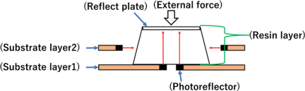
Fig. 1. Optical tactile force sensor structure.
The structure of the sensor fabricated in this study is shown in Fig. 1. It consists of two layers: a resin layer and a substrate layer. The resin layer is made of a flexible material such as transparent polyurethane resin and contains a reflect plate. The substrate layer is composed of two substrates, which are printed circuit boards made of paper phenol. The upper surface of the first substrate (substrate layer 1), where the resin layer is mounted, is left as a flat surface without any mounted components, and four photoreflector elements are arranged on the lower surface of this substrate layer. On the second substrate (substrate layer 2), four photoreflector elements are arranged vertically with respect to the printed circuit board so as to surround the resin layer.
Since there is no wiring between the resin layer and the substrate layer, there is no risk of wire breakage, and even if the resin layer becomes worn due to repeated contact with the target object, it can be easily replaced. The fabricated sensor is shown in Fig. 2. The overall configuration of the sensor consists of the optical tactile sensor and an Arduino. The deformation of the resin layer is detected by the photoreflector elements in the substrate layer, and the output voltage that changes according to the deformation is measured using an Arduino Nano microcontroller. The obtained data are transmitted to a PC and can be observed with an application for visualization.
2.3. Structure of the Substrate Layer
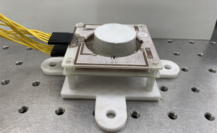
Fig. 2. Optical tactile force sensor device.
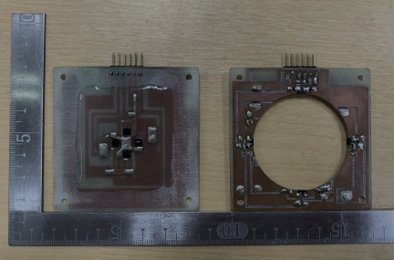
Fig. 3. Structure of the substrate layers with photoreflector arrangement.
Figure 3 shows the substrate layer. Each of the first and second substrates is a double-sided printed circuit board with a square shape of 65 mm on each side. Four photoreflectors (LBR-123f) are mounted on each layer. This device corresponds to a distance of 0–10 mm from the target object and outputs approximately 4.5–2.5 V; therefore, no external amplifier circuit is required. In addition, although each substrate is designed according to the size of the resin section, the use of double-sided boards reduces wiring through jumper wires, improving robustness and making replacement of the resin easier. Each substrate has six terminals: a 5.0 V power supply line, a GND line, and four signal lines from the photoreflectors. Furthermore, as described in Section 3, the upper surface of the photoreflector on the first-layer substrate is covered with UV resin so that it adheres closely to the resin section.
2.4. Structure of the Resin Layer
The resin layer has a tapered shape with a base diameter of \(\phi\)35.0 mm. Fig. 4 illustrates a cross-section of the resin layer. The transparent polyurethane gel is the only mechanically deformable component in the resin layer, while the reflect plate and supporting structures are rigid components. The structure consists of transparent polyurethane gel covered with a 1.0-mm-thick white layer. Inside the gel, a cylindrical acrylic plate with a diameter of \(\phi\)30.0 mm and a thickness of 2.0 mm is embedded as a reflect plate. The reflect plate is composed of stacked white and black acrylic plates; the white plate provides high infrared reflectance within the resin layer, whereas the black plate suppresses shadows of the contacting object and reduces optical interference. As shown in Fig. 4, the inner transparent polyurethane gel transmits infrared light emitted from the photoreflector elements on the first substrate, and the light is reflected by the white reflect plate. The outer 1.0-mm-thick white layer also functions as an optical shield that reduces the influence of external illumination while reflecting infrared light from the photoreflector elements on the second substrate at the side surface of the resin layer, thereby improving signal stability. The transparent urethane gel used in this study is a commercially available material manufactured by Exseal Co., Ltd., with a specified hardness of Asker C 7 (manufacturer specification).
Further details on the sensor structure and fabrication process can be found in 18,19,20.
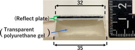
Fig. 4. Resin part structure.
2.5. Photoreflector Characteristics and Availability
During the development of the proposed sensor, it was confirmed that the originally considered photoreflector element TPR-105F had been discontinued. To ensure long-term reproducibility and practical applicability, an alternative commercially available element, LBR-123F, was evaluated. Fig. 5 shows the relationship between the distance and the output voltage for both photoreflector elements measured using a standard evaluation circuit. The horizontal axis represents the distance between the reflector and the sensor, and the vertical axis represents the measured output voltage. Both elements exhibit nonlinear response characteristics as the distance increases. Although slight differences in voltage range are observed, the overall response trends are similar. These results indicate that LBR-123F can serve as a suitable replacement without modification of the sensing principle. The observed nonlinear voltage response also suggests that higher-order modeling may be appropriate for signal interpretation; however, the final selection of the polynomial approximation is based primarily on the mechanical characteristics of the resin layer described in the following subsection.
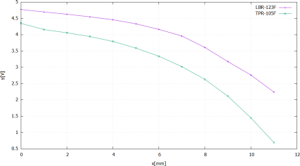
Fig. 5. Distance–voltage characteristics of two photoreflector elements.
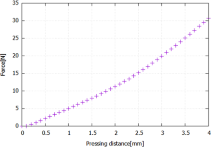
Fig. 6. Relationship between pressing displacement and elastic force of the resin layer.
2.6. Algorithm for Calculating Displacement, Force, and Rotation
Figure 6 shows the experimentally obtained relationship between pressing distance and elastic force of the resin layer measured using the six-axis force sensor. The experimental setup is illustrated in Fig. 7. In this setup, the prototype optical tactile force sensor is fixed to a three-axis translation stage, and the six-axis force sensor (BL Autotec Co., Ltd. b) is mounted on the \(z\)-stage using aluminum components. Displacement is applied by moving the \(z\)-stage, followed by controlled motion in the \(xy\)-axis directions.
As observed in Fig. 6, the elastic force varies approximately linearly for small displacements up to around 2.0 mm. However, in the range from approximately 2.0 mm to 4.0 mm, the force increases in a nonlinear manner, exhibiting a quadratic-like trend. These results indicate that a simple linear model is insufficient to accurately represent the mechanical characteristics of the resin layer over the entire operating range of the sensor.
Accordingly, polynomial approximation was adopted for estimating displacement, force, and rotational components. Preliminary comparisons were conducted using linear, quadratic, and cubic polynomial models. While the linear model failed to capture the nonlinear behavior, the cubic model did not provide significant improvement compared with the quadratic model. Therefore, quadratic approximation was selected as a reasonable balance between estimation accuracy and model simplicity.
In addition, as described in the preceding subsection, the distance–voltage relationship of the photoreflector element also exhibits nonlinear characteristics. These combined nonlinear behaviors further support the use of polynomial modeling in the estimation algorithm.
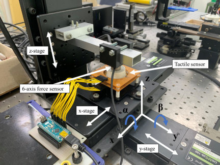
Fig. 7. Experimental setup.
The method for calculating displacement and force using the optical tactile force sensor with two substrate layers is based on the output voltages of eight photoreflector elements, as described below. Let the output voltage of the \(i\)-th photoreflector element (\(i = 1, \ldots, 8\)) be \(V_{si}\) [V]. Assuming that the displacement \(\Delta x\) [mm] in the \(x\)-axis direction is a quadratic function of the output voltages of the photoreflector elements, it is approximated by the following equation:
Here, \(C_{xj}\) (\(j = 0, \ldots, 16\)) denote the coefficients of each term. By substituting \(V_{si} = V_{Gi} + V_{i0}\) into Eq. (1), the equation can be rewritten in quadratic form with respect to the normalized variables \(V_{Gi}\). In practice, the coefficients are identified directly using the normalized variables. The normalized formulation (Eq. (2)) ensures that \(\Delta x = 0\) when \(V_{Gi} = 0\), corresponding to the no-load condition. Therefore, the constant term becomes unnecessary in the normalized model.
Here, in order to determine the coefficients \(c_{dj} \ (d = x, y, \ldots, F_z)\) of each term represented as an \(8 \times 16\) matrix, polynomial approximation using previously measured reference points is employed. For this purpose, the output voltages of the photoreflector elements at reference points within the displacement range of the resin layer, together with the corresponding three-axis displacements, forces, and rotations, are acquired in advance as calibration data. The reference points used for the polynomial approximation consist of a total of 75 points obtained by measuring 25 grid points at each of the \(z\)-axis positions of \(-1\), \(-2\), and \(-3\) mm, and a total of 34 points obtained by measuring 17 points for each rotational direction of the rotational components \(\alpha\) and \(\beta\). The coefficients are determined by least-squares approximation.
3. Improvement of Sensor Structure and Enhancement of Stability
To enable practical application of the proposed optical tactile force sensor, stability under repeated pressing and durability during prolonged contact are essential. This sensor is based on the principle of measuring the amount of reflected light inside a flexible resin layer, and the condition of the contact interface between the resin layer and the photoreflector elements directly affects the stability of the output voltage. In the initial design, when the resin layer of the optical tactile force sensor was repeatedly pressed or maintained in a deformed state for a long period, output voltage fluctuations occurred due to air movement at the contact interface between the photoreflector elements and the resin layer. Therefore, an improvement was introduced by flattening the concave lens of the photoreflector elements by applying UV resin to prevent air intrusion. Fig. 8 shows a schematic comparison between the original concave lens surface and the flattened configuration. The UV resin layer becomes mechanically rigid after curing and does not contribute to the deformation of the sensing structure. The flattened interface ensures uniform contact between the photoreflector and the resin layer, thereby suppressing air entrapment and reducing output drift.

Fig. 8. Schematic comparison of the photoreflector interface before and after flattening. The black region represents the photoreflector lens, and the blue region represents the UV resin layer used for flattening.
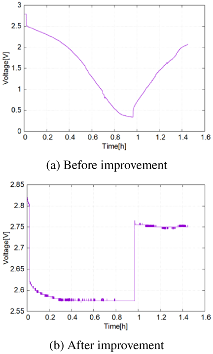
Fig. 9. Effects of implementation improvements.
Using the experimental setup shown in Fig. 7, the resin layer was brought into contact with the six-axis force sensor, and the non-deformed state was defined as 0.0 mm. The resin layer was then pressed by 2.0 mm in the \(z\)-axis direction, and the output voltage was measured while maintaining this state for 1 hour. The measurement results are shown in Fig. 9(a). The output voltage was approximately 2.5 V immediately after pressing, but decreased to about 0.4 V after 1 hour. Immediately after releasing the press, the voltage was observed to increase vertically to approximately 0.5 V; thereafter, it gradually increased, and it was confirmed that even after approximately 30 minutes, the voltage did not return to the pre-press value. In contrast, the results obtained under the same experimental conditions using the improved device are shown in Fig. 9(b). The output voltage during pressing remained almost constant, and immediately after releasing the press, the voltage increased vertically to approximately 2.75 V and then remained constant, confirming the effectiveness of the improvement.
In addition, there exist regions where the output voltage becomes constant while the sensor is kept pressed and after the press is released. The output voltage exhibits fluctuations of approximately \(\pm 5.0\) mV, reflecting the resolution of the ADC of the microcontroller. To smooth these fluctuations, a digital filter is applied. When the digital filter is applied with a sampling period of \(T = 50\) ms and a coefficient of \(a = 0.8\), the cutoff frequency \(f_c\) is approximately 0.71 Hz. Applying the filter partially smoothed the oscillations observed before the improvement, enhancing stability.
These improvements enable the proposed sensor to achieve sufficient durability and output stability for integration into devices such as robotic hands and for use in environments requiring repeated contact.
4. Experiments
4.1. Durability Evaluation of the Resin Layer
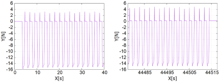
Fig. 10. 20,000 press test.
Figure 10 illustrates the relationship between the six-axis force sensor output and time during 20,000 cycles of 2 mm pressing along the \(z\)-axis. Comparison between the 1st–17th and 19,983rd–20,000th cycles shows negligible difference. An elastic force of approximately 15 N was consistently generated, indicating that the resin layer maintained flexibility without degradation or loss of restoring force. The opposite force observed upon release is attributed to adhesion between the resin layer and the six-axis force sensor, and does not affect sensor performance.
4.2. Evaluation of Accuracy and Resolution
Measurements were performed to evaluate the sensor’s accuracy and resolution for displacement and force detection. The sensor was pressed by 2.0 mm in the \(z\)-axis direction, and within a range of \(\pm 2.0\) mm in the \(xy\)-axis directions, the stage was moved along a circular path with a diameter of \(\phi 4.0\) mm. Measurements were performed at intervals of 0.1 mm in the \(x\)-axis direction.
Figure 11 shows the displacement and force results calculated from the output voltages of the sensor. In the figure, the purple points (reference points) represent the trajectory of the translation stage and the measured values obtained from the six-axis force sensor, while the green points (measuring points) represent the values of \(\Delta x\), \(\Delta y\), \(F_x\), and \(F_y\) calculated by the proposed algorithm. At this time, each prototype optical tactile force sensor outputs values at each measurement point on the circle at intervals of 0.1 mm in the \(x\)-axis direction. Similarly, the force component \(F_x\) is calculated at intervals of 0.1 N. Therefore, the resolution is less than or equal to 0.1 mm for displacement and 0.1 N for force.
In addition, to confirm whether the rotational components \(\alpha\) and \(\beta\) can be calculated, the six-axis force sensor was positioned so that it overlapped half of the tactile force sensor in the \(x\)-axis direction from the center on the \(xy\) plane. The sensor was then pressed in the \(z\)-axis direction in steps of 0.1 mm, and the rotation was varied within a range of \(\pm 16\)°. Fig. 12 shows the results, where the left side indicates rotation in the positive direction and the right side indicates rotation in the negative direction. Similarly, the purple points (reference points) indicate the locations measured to determine the coefficients \(c_{dj}\), and the green points (measuring points) indicate the calculated results.
The average error of the rotational component \(\beta\) is 0.7° for positive rotation and 1.6° for negative rotation. The resolution of the rotational component \(\beta\) is less than or equal to 0.3°.
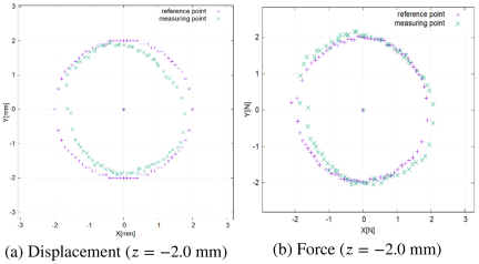
Fig. 11. Displacement and force.
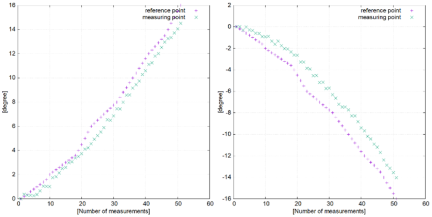
Fig. 12. \(\beta\)-axis rotation.
4.3. Evaluation of Slip Detection
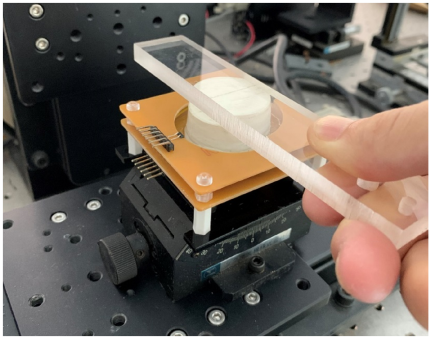
Fig. 13. Slip detection experiment.
Slip detection capability was evaluated to emulate tactile sensing functions of human skin. An acrylic square rod was pressed against the sensor and pulled horizontally to generate three slip events. Detection was performed using the \(3\sigma\) control method applied to the output voltage. Fig. 13 illustrates the experimental setup.
The output voltage was sampled at a period of 50 ms, determined by the acquisition loop of the Arduino micro-controller. For the \(3\sigma\) criterion, a sample size of \(N=49\) consecutive voltage samples was used to compute the mean \(A\) and standard deviation \(\sigma\).
In this method, let \(A\) be the mean and \(\sigma\) be the standard deviation of \(N\) output voltage samples. Slip is detected when the measured output voltage \(V_{\mathit{now}}\) falls outside the range \(A - 3\sigma \leq V_{\mathit{now}} \leq A + 3\sigma\), where \(A\) and \(\sigma\) denote the mean and standard deviation of \(N\) samples, respectively.
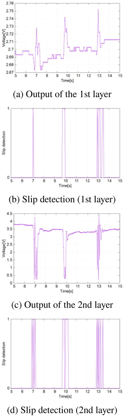
Fig. 14. Slip detection.
Figure 14 illustrates the output voltages of the first and second substrate layers during slip events, along with the slip detection results based on the \(3\sigma\) control method. During the three slip events, significant changes in output voltage occurred at 7, 10, and 13 s, indicating vibration of the resin layer at the slip moments. Applying the \(3\sigma\) criterion enabled successful detection of all three slip events. Thus, slip detection can be achieved using both substrate layers.
5. Discussion
This study comprehensively evaluated the proposed optical tactile force sensor in terms of stability under prolonged pressing, durability during repeated use, accuracy of displacement, force, and rotation estimation, and dynamic tactile sensing performance. First, in the long-term pressing test, the conventional structure exhibited significant drift caused by air movement at the interface between the resin layer and the photoreflector elements. By contrast, with the improvement achieved by flattening the concave lens of the photoreflector elements, the output voltage during holding remained nearly constant even under long-term contact, resulting in a substantial improvement in stability against prolonged pressing. In addition, the results of the 20,000-cycle repeated pressing test showed that the elastic force characteristics of the resin layer were almost identical to those observed at the initial condition. No degradation or loss of restoring force was observed, confirming high durability and practical applicability for repeated use.
Regarding the accuracy of three-axis displacement, force, and rotation estimation, displacement and force were obtained with resolutions of approximately 0.1 mm and 0.1 N, respectively, and the rotational components exhibited a resolution of less than 0.3°. However, the average error rate was approximately 10%, which is relatively high. This error can be attributed to factors such as the nonlinearity of the photoreflector output and the complex deformation distribution within the resin layer. Accuracy can be improved by increasing the dataset used to determine the coefficients \(c_{dj}\) and by introducing machine-learning-based regression models as alternatives to polynomial approximations.
Although the present study focuses on estimating rotational deformation components (\(\alpha\) and \(\beta\)), the experimental setup employed a six-axis force/torque sensor for calibration. Therefore, the measured torque data corresponding to rotational deformation are available. Future work will include calibration procedures to directly estimate torque around the \(x\)- and \(y\)-axes from the photoreflector outputs. In addition, the introduction of machine-learning-based multivariate regression models may further improve estimation accuracy and enable direct torque prediction. Such developments would allow the proposed device to function as a compact force/torque tactile sensor while maintaining its low-cost and modular characteristics.
With respect to dynamic tactile sensing, slip detection experiments demonstrated that the proposed sensor can optically capture micro-vibrations generated at the contact interface and reliably identify slip events using the \(3\sigma\) criterion. Moreover, because vibration components similar to those observed during slip detection exhibit different waveform characteristics for contact objects with different surface roughness, the proposed sensor has the potential to acquire signals that reflect differences in surface properties (texture). This behavior arises because changes in pressure distribution and micro-friction-induced vibrations associated with surface roughness are transmitted through the resin layer and appear as small fluctuations in the infrared reflection measured by the photoreflector elements. The ability to acquire dynamic tactile information using an optical system alone demonstrates the potential of the proposed sensor to realize advanced tactile functions, enabling comprehensive evaluation of contact states without additional sensors.
From a practical usability perspective, a visualization application was developed using Python to display the state of the optical tactile force sensor. The development environment was Visual Studio Code, and Python version 3.10.11 was used. In the application, three-axis displacement is represented by the position and size of black markers, while the magnitudes of the rotational components \(\alpha\) and \(\beta\) are represented by the rotation of lines in the graph on the right-hand side. The application interface is shown in Fig. 15.
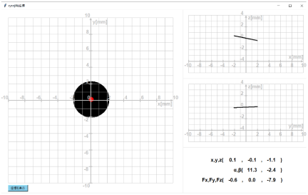
Fig. 15. Example of visualizing the proposed sensor’s output.
6. Conclusion
This study developed and enhanced an optical tactile force sensor utilizing a flexible resin. Revising the mounting method of photoreflector elements, flattening the lens surface, and applying digital filtering for signal smoothing significantly improved the sensor’s stability and practical applicability. Experimental results confirmed that the resin layer maintained high durability without degradation after 20,000 pressing cycles and enabled acquisition of dynamic tactile information associated with slip events using optical sensing alone. In addition, the proposed sensor achieved resolutions of approximately 0.1 mm in displacement, 0.1 N in force, and 0.3° in rotation. These findings demonstrate that the sensor is a compact, low-cost tactile device capable of simultaneously measuring multiple physical quantities with high resolution.
On the other hand, at the current stage, the slip detection response is primarily sensitive to large-amplitude events, and the estimation error rates for displacement, force, and rotation still leave room for improvement. These limitations can be mitigated through refined modeling, machine-learning-based multivariate regression, and further structural optimization. In future work, the proposed sensor will be integrated into robotic arms and multi-fingered hands to demonstrate dynamic tactile functions, and the device will be further developed toward applications involving advanced manipulation and palpation tasks approaching human tactile capability 21.
- [1] M. Goka, N. Nakamoto, Y. Takenawa, and N. Kida, “Design of downsized magnetic type tactile sensor,” Trans. JSME, Series C, Vol.76, No.772, pp. 3640-3647, 2010 (in Japanese). https://doi.org/10.1299/kikaic.76.3640
- [2] N. Nakamoto, M. Goka, Y. Takenawa, and N. Kida, “A magnetic type tactile sensor using GMR eiements and inductors,” Trans. JSME, Series C, Vol.76, No.766, pp. 1476-1482, 2010 (in Japanese). https://doi.org/10.1299/kikaic.76.1476
- [3] K. Hoshino, D. Mori, and M. Tomida, “An optical tactile sensor assuming cubic polynomial deformation of elastic body,” J. Robot. Mechatron., Vol.21, No.6, pp. 780-788, 2009. https://doi.org/10.20965/jrm.2009.p0780
- [4] S. Saga, H. Kajimoto, and S. Tachi, “High-resolution tactile sensor using the deformation of a reflection image,” Sensor Review, Vol.27, No.1, pp. 35-42, 2007. https://doi.org/10.1108/02602280710723451
- [5] A. Padmanabha, O. Khatib, R. Calandra, and M. Sundaralingam, “OmniTact: A multi-directional high-resolution tactile sensor,” 2020 IEEE Int. Conf. on Robotics and Automation (ICRA), pp. 618-624, 2020. https://doi.org/10.1109/ICRA40945.2020.9196712
- [6] M. Lambeta, P.-W. Chou, S. Tian, B. Yang, B. Maloon, A. Nayebzadeh, R. Calandra, and R. Hariharan, “Digit: A novel design for a low-cost compact high-resolution tactile sensor with application to in-hand manipulation,” IEEE Robotics and Automation Letters, Vol.5, No.3, pp. 3838-3845, 2020. https://doi.org/10.1109/LRA.2020.2977257
- [7] Gao et al., “TACTO: A fast, flexible, and open-source simulator for high-resolution vision-based tactile sensors,” IEEE Robotics and Automation Letters, Vol.7, No.2, pp. 3930-3937, 2022. https://doi.org/10.1109/LRA.2022.3146945
- [8] N. F. Lepora, “Soft biomimetic optical tactile sensing with the TacTip: A review,” IEEE Sensors J., Vol.21, No.19, pp. 21131-21143, 2021. https://doi.org/10.1109/JSEN.2021.3100645
- [9] J. W. James, S. J. Redmond, and N. F. Lepora, ”A biomimetic tactile fingerprint induces incipient slip,” 2020 IEEE/RSJ Int. Conf. on Intelligent Robots and Systems (IROS), pp. 9833-9839,2020. https://doi.org/10.1109/IROS45743.2020.9341310
- [10] D. F. Gomes, Z. Lin, and S. Luo, “GelTip: A finger-shaped optical tactile sensor,” 2020 IEEE/RSJ Int. Conf. on Intelligent Robots and Systems (IROS), pp. 9903-9909, 2020. https://doi.org/10.1109/IROS45743.2020.9340881
- [11] E. Donlon, S. Dong, M. Liu, J. Li, E. Adelson, and A. Rodriguez, “Gelslim: A high-resolution, compact, robust, and calibrated tactile-sensing finger,” 2018 IEEE/RSJ Int. Conf. on Intelligent Robots and Systems (IROS), pp. 1927-1934, 2018. https://doi.org/10.1109/IROS.2018.8593661
- [12] S. Dong, W. Yuan, and E. H. Adelson, “Improved GelSight tactile sensor for measuring geometry and slip,” Proc. IEEE/RSJ Int. Conf. Intelligent Robots and Systems (IROS), pp. 137-144, 2017. https://doi.org/10.1109/IROS.2017.8202149
- [13] M. Yukihira and M. Goka, “Miniaturization of an optical tactile sensor and its application to soft robotics,” Proc. of 25th SICE System Integration Division Annual Conf. (SI2023), 2023 (in Japanese).
- [14] M. Yukihira and M. Goka, “Development and performance evaluation of an optical tactile sensor using transparent flexible resin,” Proc. of the SICE Annual Conf. 2024, pp. 294-299, 2024.
- [15] M. Yukihira and M. Goka, “Improvement of an optical tactile sensor and its application,” Proc. 33rd SICE Chugoku Chapter Annual Conf., pp. 17-18, 2024 (in Japanese).
- [16] T. Baumberger and C. Caroli, “Solid friction from stick–slip down to pinning and aging,” Advances in Physics, Vol.55, Nos.3-4, pp. 279-348, 2006. https://doi.org/10.1080/00018730600732186
- [17] R. S. Johansson and J. R. Flanagan, “Coding and use of tactile signals from the fingertips in object manipulation tasks,” Nature Reviews Neuroscience, Vol.10, pp. 345-359, 2009. https://doi.org/10.1038/nrn2621
- [18] M. Goka, “Optical tactile sensor using transparent flexible resin,” N. Tanio (Ed.), “High-Performance Transparent Polymers: Development and Applications,” CMC Publishing Co., Ltd., pp. 216-223, 2022 (in Japanese).
- [19] M. Goka, “Development of an optical tactile sensor using transparent soft resin,” Japan Plastics, Vol.72, No.6, pp. 123-127, 2021 (in Japanese).
- [20] M. Goka, “Optical tactile sensor using transparent flexible resin,” Bio Industry, Vol.38, No.6, pp. 24-31, 2021 (in Japanese).
- [21] M. Tanaka, “Investigation of Tactile Mechanism and a Tactile Sensor System,” J. of the Japan Society for Precision Engineering, Vol.82, No.1, pp. 20-25, 2016. https://doi.org/10.2493/jjspe.82.20
- [a] OnRobot, “OptoForce Force/Torque Sensors.” https://onrobot.com/en/products/optoforce [Accessed May 20, 2026]
- [b] BL AUTOTEC Co., Ltd., “6-Axis Force Sensor Product Information.” https://www.bl-autotec.co.jp/products/ [Accessed February 15, 2025]
This article is published under a Creative Commons Attribution-NoDerivatives 4.0 Internationa License.