Paper:
Pick-and-Place Motion by Two-Robot-Arm System Equipped with Variable-Stiffness and Deformable Link Using Shape-Memory Alloy and Jamming Transition Phenomenon
Kazuto Takashima*,†
 , Yuma Hirose*, Hidetaka Suzuki*, and Hiroki Cho**
*Graduate School of Life Science and Systems Engineering, Kyushu Institute of Technology
2-4 Hibikino, Wakamatsu-ku, Kitakyushu, Fukuoka 808-0196, Japan
†Corresponding author
**Faculty of Environmental Engineering, The University of Kitakyushu
1-1 Hibikino, Wakamatsu-ku, Kitakyushu, Fukuoka 808-0135, Japan

Robotics is applied in various fields and thus robot components with various shapes and stiffness values are required. We previously developed a variable-stiffness and deformable link using a shape-memory alloy and the jamming transition phenomenon. The link can be fixed in an arbitrary shape and then restored to its initial shape via the shape memory effect. We previously attached a prototype link to a robot arm and evaluated its pick-and-place motion for various objects with different shapes and weights. However, as we used a lubricant to facilitate deforming the link, objects sometimes slipped off the link. Therefore, in this study, we propose a method for deforming the link without a lubricant. Another robot arm is added to press a mold onto the link to increase operational efficiency. We compare three deformation methods in terms of the time required to change molds, weight capacity, structural change during repeated motion, force required to deform the link, and positioning accuracy. The experimental results show that the weight capacity increased when the link was deformed without a lubricant. Moreover, similar to our previous study, changing the link shape to suit the target object improved positioning accuracy. Using the two-robot-arm system, the time required to change molds decreased by 94% compared to that in our previous study. Furthermore, the pressing force of the link during the fixing of the shape affected the contact length between the link and the object and the positioning accuracy.
Application of variable-stiffness link
1. Introduction
In rapidly aging societies, the application of robots has spread from industry to nursing and social welfare, where soft robots [1–24] are necessary to minimize the possibility of human injury. However, numerous robot components with various shapes, sensitivities, and stiffness values are required for a given application of interest because the designs of industrial and non-industrial robots are different.
Variable-stiffness mechanisms establish a bridge between rigid, precise industrial robots and soft, compliant non-industrial robots 1. For example, numerous variable-stiffness joint mechanisms in which a pair of actuators is antagonistically configured have been developed 2. Moreover, by utilizing the jamming transition phenomenon 1,3,4,5,6,7,8,9,10,11, a shape-memory gel 12, a low-melting-point alloy 3,13,14, or electrorheological and magnetorheological fluids 3, the stiffness and structure of robot components can be changed for different tasks. For example, the jamming transition phenomenon for a granular material 1,3,4,5,6,7,8,9,10, which can be produced by venting air from a space containing particles, has been widely used to change the stiffness of a robot component. The stiffness change achievable with this technology has been reported to be up to 24-fold and the rate of stiffness change is rather fast (0.1–1.1 s to solidify, 0.1–1 s to liquefy) 3. Despite its simple mechanism, granular jamming has superior characteristics in many applications 1,3,4,5,6,7,8,9,10. Before air is vented, the jamming mechanism can passively conform to a wide variety of arbitrarily shapes. One representative example of a device that utilizes this characteristic is the universal soft gripper 7, which can handle a wide range of objects in pick-and-place operations.
We previously developed robot components with variable stiffness and sensitivity based on shape-memory materials (SMMs) whose stiffness changes with temperature 25,26,27,28,29,30,31. For example, we proposed pneumatic artificial muscles 25,26 and force sensors 27,28 that use SMMs. This makes it possible to change the temperature to switch the functionality as desired between a soft non-industrial robot and an accurate and rigid industrial robot. By utilizing the stiffness change of the material itself, variable-stiffness mechanisms that use SMMs have relatively few components and can be used in a small space. As shown in our previous studies 25,26,27,28,29,30,31, such mechanisms can be applied to most parts of a robot because they do not limit the scalability and mobility of the robot.
Many robots consist of rigid links and joints driven by actuators. Because an increase in the number of robot joints enables more complicated tasks to be performed, various types of hyper-redundant manipulators have been developed 32. However, robots with many joints tend to be heavy and expensive. Therefore, continuum robot arms, which mimic biological systems such as octopus arms, ostrich necks, and elephant trunks, have also been developed 15,16,17,18,19. However, such systems are not capable of both passively conforming to their environments and maintaining complex configurations.
In our previous studies 29,30,31, we developed a variable-stiffness deformable link based on a shape-memory polymer (SMP) or shape-memory alloy (SMA) 3,4,5,20,21,22,33,34,35 and the jamming transition phenomenon. Although granular jamming has disadvantages in terms of shape recovery 11, the shape recovery force of SMPs or SMAs can be used instead. Cheng et al. 6 inserted springs into the jamming mechanism to help return the mechanism to a neutral position when unjammed; however, the spring had low stiffness. In our previous study 29, we evaluated a prototype link that consisted of two SMP sheets or four SMA wires inserted in the jamming mechanism. Experiments using prototype links confirmed that the stiffness and shape of these links can be changed according to the temperature and pressure. Moreover, the links could support their own weight even when unjammed, in contrast to a conventional manipulator based on the jamming transition phenomenon, which is barely strong enough to support its own weight 6. Even after a 2-kg load was applied, the shape of the prototypes remained fixed. The combination of an SMM and the jamming effect allows four stiffness states to be achieved.
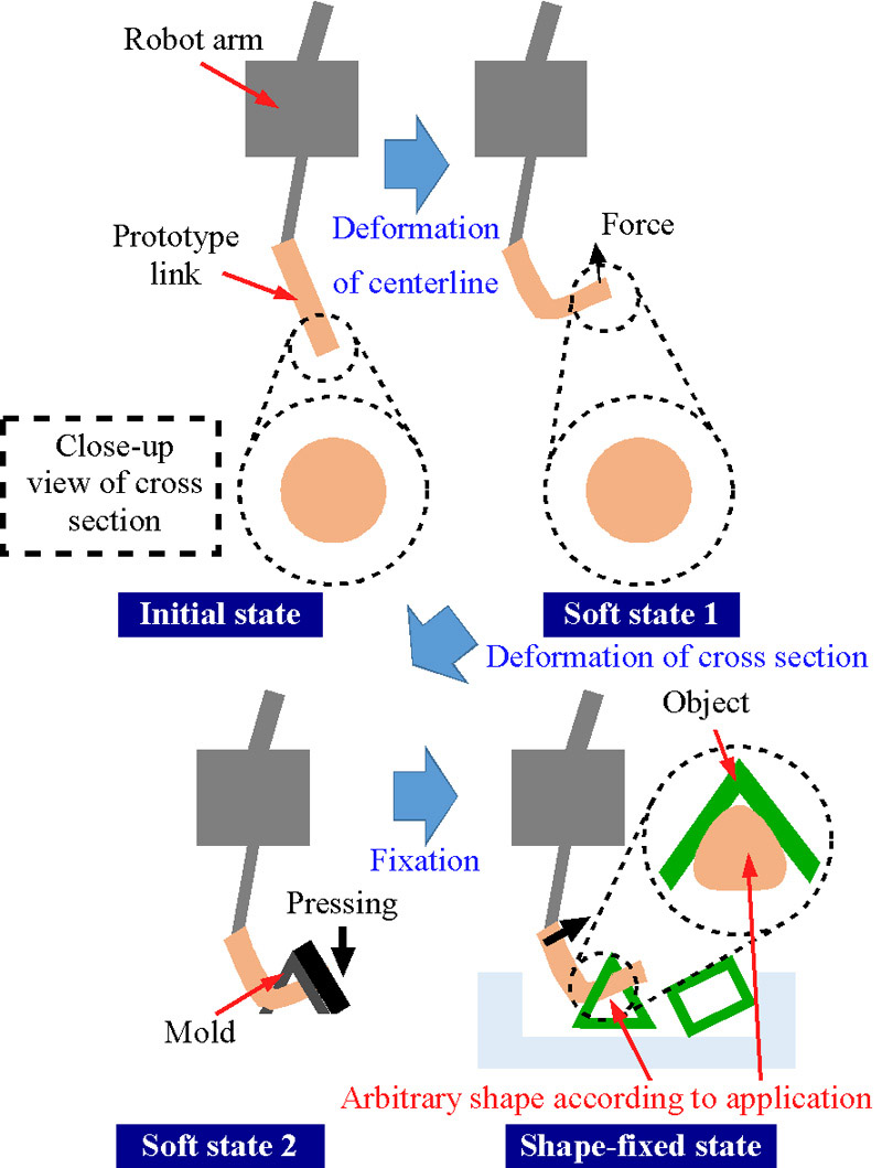
Moreover, in our previous study 30, we attached our link to a robot arm and evaluated the motion shown in Fig. 1. For the evaluation, we used a prototype link to pick up and move various objects with different shapes and weights. Without additional joints and actuators, the proposed link could be deformed into a shape suitable for a specific task (e.g., gripping of various objects (Fig. 1), walking on a pillar, climbing a ladder, or positioning of a catheter tip), similar to the case for an SMM 12,23 or a low-melting-point alloy 13,14. Note that our proposed link can be fixed in an arbitrary shape faster using jamming, whose activation time for achieving the transition between a compliant state and a rigid, load-bearing state is short. For example, as shown in Figs. 1(b) and (c), after a straight link is softened, it can be deformed into various shapes by an external load (e.g., generated by insertion into a mold or by another robot arm) to increase positioning accuracy and weight capacity (Fig. 1(d)). Consequently, numerous links with various shapes are not required for different tasks. Moreover, unlike the deformable links in previous research, the proposed link utilizes not only a centerline change (Fig. 1(b)) but also a cross-sectional change (Fig. 1(c)). Experiments confirmed that changing and fixing the link shape (the centerline and the cross section) to suit the target object increased both positioning accuracy and weight capacity.
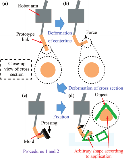
Fig. 1. Robot arm application of variable-stiffness link using SMM and jamming transition phenomenon. (a) Initial state, (b) soft state 1, (c) soft state 2, (d) shape-fixed state.
However, as we used a lubricant and inserted the link into a mold to deform it, the objects sometimes slipped off the link. Therefore, in this study, we propose a method for deforming the link without a lubricant (procedures 1 and 2 in Fig. 1(c)). Moreover, another robot arm is added to press the mold onto the prototype link to increase operational efficiency. We compare three procedures in terms of the time required to change the molds, weight capacity, structural change during repeated motion, force required to deform the link, and positioning accuracy.
2. Experiment
2.1. Concept of Variable-Stiffness Link Based on SMA and Jamming Transition Phenomenon
In this study, we used a prototype link based on an SMA. Compared to SMPs, SMAs have larger recovery stress, larger thermal conductivity, and higher electrical conductivity 33. An SMA is rigid at high temperature and flexible at low temperature. The transformation starts when the temperature reaches the austenite start temperature (\(A_s\)) for heating.
A schematic diagram of the operation of our variable-stiffness link based on an SMA and the jamming transition phenomenon is shown in Fig. 2. By applying an external load, the link can be deformed into an arbitrary shape with a different centerline and cross section (s1 \(\to\) s2). By exhausting the interior air, the jamming transition phenomenon can be used to maintain the deformed shape (s2 \(\to\) s3). For example, as shown in Fig. 1, the proposed link can be deformed and fixed into a specific shape suitable for a specific task. Then, after air is injected and the SMA is heated, the link returns to its initial shape via shape recovery (s3 \(\to\) s4). After cooling, the link returns to its initial state (s4 \(\to\) s1).
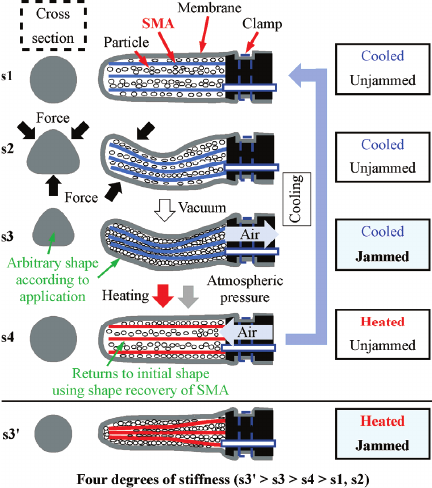
Fig. 2. Principle of motion for variable-stiffness link using SMA wires and jamming transition phenomenon.
2.2. Prototype
The prototype link (Fig. 3) used in this study was fabricated using a process similar to that in our previous study 29,30. We inserted four straight Ni-Ti SMA wires (Nilaco Corp., 946485, outer diameter: 1.0 mm, \(A_s=60°\)C) into a jig (polylactic acid, PLA) created by a 3D printer. As shown in Fig. 3(b), the four SMA wires were arranged in a circle. The total resistivity of the four SMA wires connected in series was 0.46 \(\Omega\) at room temperature. We prepared a plug made of silicone rubber (Shin-Etsu Chemical Co., Ltd., KE-106) for the jig to decrease air leakage. To change the inner pressure, tubes were inserted into the jig and the rubber plug. We prepared an outer membrane made of silicone rubber (Smooth-On Inc., Ecoflex 00-30) for the jamming mechanism using a mold. As the particles for the jamming transition phenomenon, we inserted coarse coffee grounds (26 g) around the SMA wires in the outer membrane, which was attached to the jig using a cable tie. The total weight of the prototype including the jig, tubes, and wires was 152 g. We heated the SMA wires by applying 3 VAC directly with a slidac transformer. To realize the jamming transition phenomenon, we exhausted the air in the membrane to below \(-90\) kPa using a vacuum pump. The performance of the prototype link measured in our previous study is shown in Table 1.
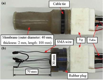
Fig. 3. Prototype of variable-stiffness link using SMA wires and jamming transition phenomenon. (a) External appearance, (b) internal components.
Table 1. Performance of proposed link 29.


Fig. 4. Experimental apparatus for evaluating pick-and-place motion by prototype link. (a) Procedure 2, close-up views of yellow dotted rectangle in (b) procedure 0 and (c) procedure 1.
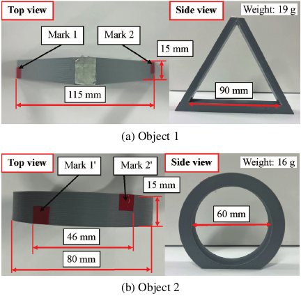
Fig. 5. Photographs of objects used in evaluation.
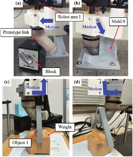
Fig. 6. Motion of proposed variable-stiffness link (procedure 0). (a) Motion (i), (b) motion (ii), (c) motion (iv), (d) motion (v).
2.3. Experimental Apparatus and Method for Deforming Link
A photograph of the experimental apparatus used to evaluate the pick-and-place motion of the prototype link is shown in Fig. 4. The yellow dotted square area in Fig. 4(a) shows the modified part from our previous study 30. In this study, we evaluated the motion of the prototype link attached to robot arm I (Dobot, Magician). Two types of object with different shapes and weights (Fig. 5) were hooked onto the prototype link. We chose these objects assuming the use of a container with a handle or a tube bundle in a factory or a skillet lid or a pitcher in daily life. The motion is shown in Fig. 6. In our previous study 30, we used procedure 0 to deform the link according to the object. Procedure 0 was as follows:
-
(i)
Using the horizontal rotation of robot arm I, we moved and pushed the prototype link against a block to apply bending deformation (s1 \(\to\) s2, Fig. 6(a)). After this deformation, the link could be easily inserted into the mold.
-
(ii)
To obtain the desired shape, we moved the link and inserted it into mold 0 using robot arm I (Fig. 4(b)) (s1 \(\to\) s2, Fig. 6(b)). The inner shapes of mold 0 gradually become similar to those of the objects.
-
(iii)
We exhausted the air to fix the deformed shape (s3).
-
(iv)
We moved the link to the picking area and lifted the object by hooking it onto the prototype link (Fig. 6(c)).
-
(v)
Using robot arm I, we moved the object horizontally to the placing area and placed it there. Then, we pulled the link away from the object (Fig. 6(d)).
Although procedure 0 appears simpler and more practical as it is completed entirely within the arm itself, it was impossible to insert the link into mold 0 without a lubricant. Moreover, even in the presence of a lubricant, the fixed link shape is limited to that which forms by gradual thickening from the tip. Therefore, in procedure 0, because we lubricated the molds and the prototype link using silicone spray (Kure Engineering Ltd., 1420) to enable insertion, the objects sometimes slipped off the link. Therefore, in this study, we evaluated procedures 1 and 2 without the use of silicone spray. As shown in Figs. 4(c) and 7, in procedure 1, we changed motions (i) and (ii) into motions (i\('\)) and (ii\('\)), respectively, as described below.
-
(i\('\))
Using robot arm I, we moved and pushed the prototype link against an inclined block (Fig. 8) prepared by a 3D printer to apply bending deformation (s1 \(\to\) s2, Fig. 7(a)).
-
(ii\('\))
Using two linear automatic stages (Sigma Koki Co., Ltd., SGSP20-85, SGSP26-50), we pressed the mold (Fig. 9), which was attached to the automatic stage, onto the link to obtain the desired shape (s1 \(\to\) s2, Fig. 7(b)).

Fig. 7. Motion of proposed variable-stiffness link (procedure 1). (a) Motion (i\('\)), (b) motion (ii\('\)).
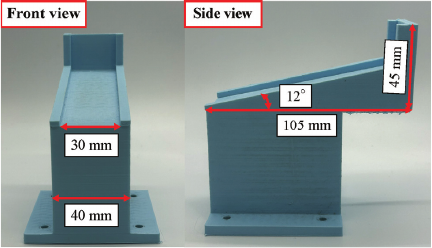
Fig. 8. Photographs of inclined block.
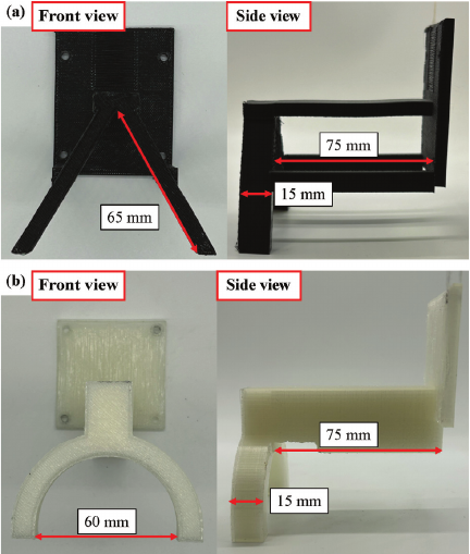
Fig. 9. Molds for objects. (a) Mold 1 for object 1, (b) mold 2 for object 2.
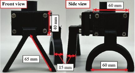
Fig. 10. Mold 3.
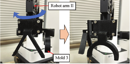
Fig. 11. Rotation of mold 3 by robot arm II (procedure 2).
However, in procedure 1, it is necessary to change the molds (Fig. 9) according to the object. Therefore, in this study, as shown in Fig. 4(a), we added robot arm II (Dobot, Magician; procedure 2). In procedure 2, we attached mold 3 (Fig. 10) prepared by a 3D printer to the tip of robot arm II and enabled the automatic replacement of the molds via the rotation of robot arm II (Fig. 11). In motion (ii\('\)) of procedure 2, we used robot arm II, not the automatic stages. We aimed to increase operational efficiency by adopting two robot arms.
2.4. Experimental Method
In this study, to compare procedures 0, 1, and 2, we evaluated pick-and-place motion for various objects with different shapes and weights in terms of the time required to change molds, weight capacity, structural change during repeated motion, force required to deform the link, and positioning accuracy. Similar to our previous study 30, in procedure 0, we lubricated the prototype link even when no mold was used to keep the conditions constant.
2.4.1. Measurement of Time Required to Change Molds
Unlike in procedures 0 and 1, it is not necessary to change the molds in procedure 2. To quantitatively compare the operational efficiency among the three procedures, we measured the time required to change the molds 5 times. Molds 0 and 1 are fixed by four screws. It is necessary to loosen and fasten these screws in procedures 0 and 1.
2.4.2. Evaluation of Weight Capacity
We evaluated the weight capacity of the prototype link. We changed the object weight by hooking another weight (320, 640, or 990 g) onto object 1. These weights were 211%, 421%, and 651% of the link weight (152 g) and similar to those of the skillet lid (652 g) and pitcher (base part) (178 g) shown in YCB Objects and Model Set 36, which are used for benchmarking in manipulation research. In our previous study 30, the difference in the experimental results on weight capacity obtained using objects 1 and 2 was small. Therefore, we used only object 1 for this evaluation. In each procedure, we compared two states of the prototype link, namely with and without motion (ii) or (ii\('\)), in terms of whether the object could be moved to the placing area. To keep the conditions constant, we heated the SMA and returned the link to its initial shape after each pick-and-place motion trial. We conducted 10 trials and calculated the success rates of procedures 1 and 2. We compared the success rates with that of procedure 0 shown in our previous study 30. Moreover, we evaluated the appearance of the link and the object during motion (iv) in terms of the link size and the contact length between the link and object 1.
2.4.3. Evaluation of Repeated Motion
To examine the durability of the fixed shape of the link, we evaluated the repeated motion of the link. After each pick-and-place motion trial, we repeated the motion without returning the link to its initial shape (i.e., we did not heat the SMA). We evaluated the number of repeated motions in which the object could be moved to the placing area. We used a 990-g weight for this evaluation. The maximum number of repeated motions was 500. Similar to Section 2.4.2, we used only object 1 and compared two states, namely with and without motion (ii) or (ii\('\)). Moreover, we evaluated the link appearance before and after the experiments. We conducted three trials for each condition.
2.4.4. Measurement of Force Required to Deform Link and Contact Length Between Link and Object
In procedure 0, the link was deeply inserted into mold. Unlike in procedure 0, in procedures 1 and 2, it is necessary to determine the distance and the force required to deform the link. Therefore, in procedures 1 and 2, we measured the force required to deform the link using a load cell (Kyowa Electronic Instruments Co., Ltd., LU-5KA). We modified the shape of the block (Fig. 8) and placed the load cell under the block (Fig. 4(a)). In procedure 1, after contact between the link and the mold, we moved the link vertically for a certain distance (hereafter, full distance refers to 15.2 and 12.4 mm for objects 1 and 2, respectively) until the link was fully deformed (as visually confirmed). In procedure 2, using robot arm II, we moved the link for the full distance. Moreover, in procedure 2, we also used the half distance (7.6 and 6.2 mm for objects 1 and 2, respectively). We conducted five trials for each condition. Moreover, during motion (iv), we measured the contact length between the link and the object.
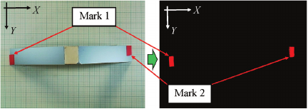
Fig. 12. Image analysis process.
Table 2. Time required to change molds (average \(\pm\) standard deviation of five measurements).

2.4.5. Evaluation of Positioning Accuracy
We evaluated the positioning accuracy of objects 1 and 2 in the placement position. As shown in Fig. 4(a), top-view images of the placed objects were acquired using a USB camera (Hozan Tool, L-835, screen resolution: \(1280\times 960\), frame rate: 30 fps) with a C-mount lens to evaluate positioning accuracy. As shown in Fig. 12, we calculated the center of gravity at Marks 1, 2, 1\('\), and 2\('\) (Figs. 5(a) and (b)) via binarization and noise reduction (particle filter) using NI Vision Assistant (National Instruments Co.). In Fig. 12, the \(X\)- and \(Y\)-axes in the placing area are shown. A length of 1 mm corresponds to 7.8 pixels. In each procedure, we compared two states of the prototype link, namely with and without motion (ii) or (ii\('\)), in terms of positioning accuracy. To keep the conditions constant, we heated the SMA to return the link to its initial shape before the next trial. We conducted 10 trials. Moreover, during motion (iv), we measured the contact length between the link and the object.
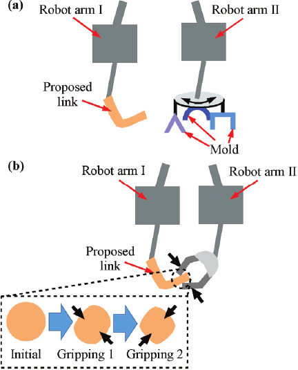
Fig. 13. Motion of robot arm II. (a) Rotation of molds, (b) gripping by robot hand.
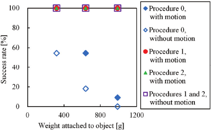
Fig. 14. Success rates of payload experiments.
3. Results and Discussion
3.1. Measurement of Time Required to Change Molds
The time required to change the molds is shown in Table 2. By utilizing mold 3 (Fig. 10), the time for procedure 2 became shorter than those for procedures 0 and 1. With the two-robot-arm system, there was a 94% decrease in the time required to change the molds compared to that in our previous study (procedure 0). Moreover, it is possible to prepare various types of shapes (more than two) in mold 3 to accommodate different objects (Fig. 13(a)). Also, by attaching a robot hand to robot arm II and performing repeated gripping from various directions, an arbitrary shape can be produced (Fig. 13(b)).
3.2. Evaluation of Weight Capacity
Figure 14 shows the success rates of payload experiments. The appearance of the link and the object during motion (iv) is shown in Figs. 15(a)–(c) and Figs. 16(a) and (b). The size and the contact area length between the link and object 1 are shown in Figs. 15(d) and 16(c), respectively. As shown for procedure 0 in Fig. 14, the weight capacity of the link was improved when the link shape was changed to suit the target object. One reason for this is that the increase in the contact area between the link and the target object (Fig. 16) led to stable pick-and-place motion.
Unlike for procedure 0, for procedures 1 and 2, all trials were successful regardless of the weight (Fig. 14) even though the contact length changed (Fig. 16). One reason for this is that we did not use a lubricant and thus friction increased. Another reason is that, as shown in Figs. 15(b) and (c), we could transform the link tip upwards using the inclined block (Fig. 8) and improved the fit to the jig by pressing the link directly.
To examine the effect of the lubricant, we also conducted procedure 2 in the presence of a lubricant. The success rates of payload experiments are shown in Fig. 17. Compared with Fig. 14, although the success rates were lower without motion (ii\('\)) in Fig. 17, procedure 2 was better than procedure 0. This is because not only the lubricant but also the deformed shape improved the success rate.
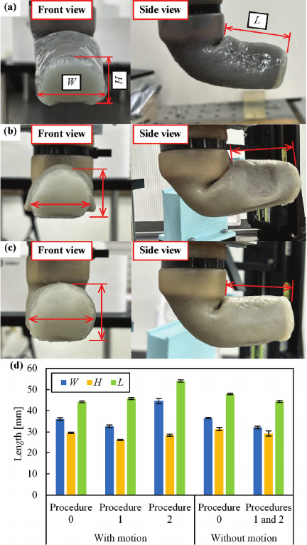
Fig. 15. Appearance of link during motion (iv). The objects were removed to make it easier to see the link. (a) With motion (ii) (procedure 0), (b) with motion (ii\('\)) (procedure 1), (c) without motion (ii\('\)) (procedure 1), (d) size of link (average \(\pm\) standard deviation of five measurements; \(W\): width, \(H\): height, \(L\): length).
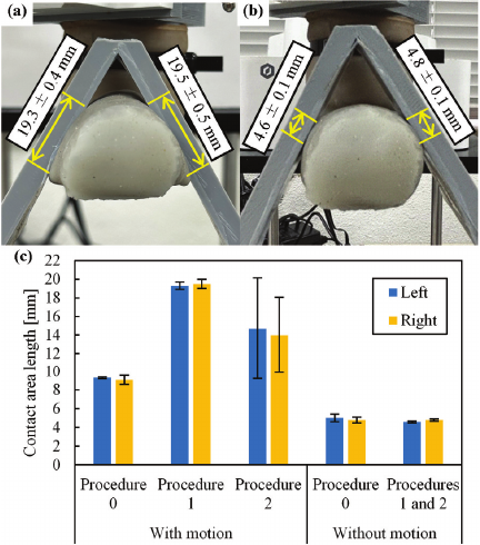
Fig. 16. Appearance of link and object during motion (iv). (a) With motion (ii\('\)) and (b) without motion (ii\('\)) (procedure 1, 990-g weight). (c) Contact area length between link and object 1 (average \(\pm\) standard deviation of five measurements).
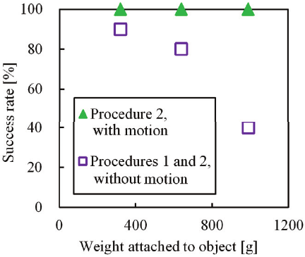
Fig. 17. Success rates of payload experiments (procedure 2 with lubricant).
The results show that the proposed method improved the pick-and-place motion by not using silicone spray and by improving the fixed shape. Many industrial manipulators can support payloads that are only a fraction of their own weight 37. Cheng et al. 6 reported that a manipulator based on granular jamming was able to support a payload equal to more than 200% of its own weight. Note that these previously reported values are smaller than that for our link, as shown in Fig. 14, because the weights used in this study were 211%, 421%, and 651% of the link weight. Therefore, the load capacity is considered sufficient.
Table 3. Number of successes in three procedures.

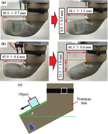
Fig. 18. Shape of link before and after experiment (procedure 1). (a) With motion (ii\('\)), (b) without motion (ii\('\)). The size of the link (average \(\pm\) standard deviation of three measurements) is also shown. (c) Slipping and dropping of object after bending of link.
3.3. Evaluation of Repeated Motion
Table 3 shows the number of successes for the three procedures. The link appearance before and after the experiment with procedure 1 is shown in Figs. 18(a) and (b). As shown in Table 3, the numbers of successes for procedures 1 and 2 are higher than that for procedure 0. Similar to Section 3.2, the increase in friction on the surface affected the experimental results. Moreover, for procedure 1, as shown in Figs. 18(a) and (b), the link shape without motion (ii\('\)) greatly changed. By changing the link shape according to the object, the durability of the fixed shape increased. One reason for this is that the increase in contact area caused by changing the link shape according to the object dispersed the shock and the load when the weight made contact with the link.
As shown in Fig. 18(c), when the link tip was gradually bent and inclined, the object slipped and eventually dropped. Using the static friction coefficient (\(\mu\)), the initial inclination angle (\(\theta\)) at which the object begins slipping can be calculated as follows:
Table 4. Force required to deform link (average \(\pm\) standard deviation of five measurements).

3.4. Measurement of Force Required to Deform Link and Contact Length Between Link and Object
The force required to deform the link and the contact length between the link and the object are shown in Table 4 and Fig. 19, respectively. For the full distance for both objects 1 and 2, the difference between procedures 1 and 2 was small. Namely, the automatic stages and robot arm II were used similarly. As shown in Fig. 19, the experimental results for procedure 2 show that, for both objects, the smaller movement distance of the link (half distance) led to a smaller contact length between the link and the object. Furthermore, the force for object 1 was larger than that for object 2. This could be attributed to the longer movement distance.
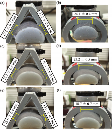
Fig. 19. Appearance of link and object during motion (iv) (with motion (ii\('\))). (a) Object 1 (procedure 1, full), (b) object 2 (procedure 1, full), (c) object 1 (procedure 2, full), (d) object 2 (procedure 2, full), (e) object 1 (procedure 2, half), (f) object 2 (procedure 2, half). The contact area length between the link and the object (average \(\pm\) standard deviation of five measurements) is also shown.
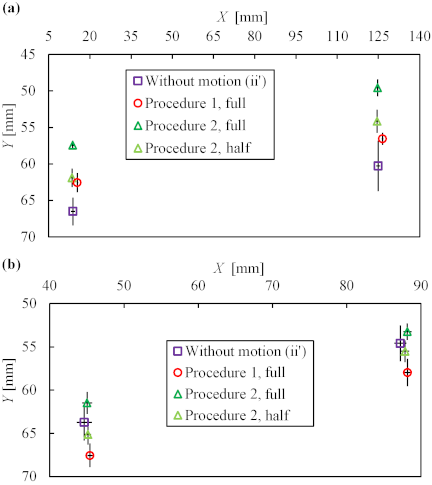
Fig. 20. Placed positions (average \(\pm\) standard deviation of ten measurements). (a) Object 1, (b) object 2.
3.5. Evaluation of Positioning Accuracy
Figures 20(a) and (b) show the placed positions of objects 1 and 2, respectively. The contact length between the link and the object without motion (ii\('\)) is shown in Fig. 21. The difference between objects 1 and 2 for procedures 1 and 2 was small. For both procedures, the standard deviation of the placement positions for both objects decreased with the addition of motion (ii\('\)). In other words, changing the link shape to suit the target object improved positioning accuracy. One reason for this improvement is that by changing the link shape to suit the target object, the contact area between the link and the object was increased (Figs. 19 and 21) and thus stable pick-and-place motion without object movement on the link was achieved.
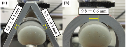
Fig. 21. Appearance of link and object during motion (iv) (without motion (ii\('\))). (a) Object 1, (b) object 2. The contact area length between the link and the object (average \(\pm\) standard deviation of ten measurements) is also shown.
For procedure 2 using object 1 (Fig. 20(a)), the standard deviation for the full distance was smaller than that for the half distance. One reason for this is that, as described above, the contact length between the link and the object for the full distance was longer than that for the half distance (Fig. 19) and stable pick-and-place motion became possible. On the other hand, for procedure 2 using object 2 (Fig. 20(b)), the difference between the full distance and the half distance was small. One reason for this is that it is possible to deform the desired cylindrical shape using a small movement distance because the initial cross-sectional shape of the link was also cylindrical. As shown in Table 4, because the force for the half distance was smaller than that for the full distance, it may be unnecessary to use the full distance for procedure 2 using object 2.
3.6. Future Issues
In this study, we hung an object on the proposed link and performed a pick-and-place motion. In our previous study 29, we showed that the proposed link can wrap around and grip various objects, similar to conventional jamming grippers, at room temperature. In a future study, we will use the link to wrap around objects and perform a pick-and-place motion.
In this study, the initial shape of the proposed link was straight. We bent the link using a block, as shown in Figs. 6(a) and 7(a). In a future study, we will utilize a bent SMA wire to realize the initial bent shape.
4. Conclusion
In this study, we attached a prototype link that uses SMA wires and the jamming transition phenomenon to a robot arm and evaluated its pick-and-place motion. We proposed a method for deforming the link without a lubricant. Another robot arm was added to press the mold onto the link to increase operational efficiency. We evaluated the link performance in terms of the time required to change the molds, weight capacity, structural change during repeated motion, force required to deform the link, and positioning accuracy. The experimental results show that the weight capacity increased by not using silicone spray and by improving the fixed shape. Moreover, similar to our previous study, changing the link shape to suit the target object improved positioning accuracy. Using the two-robot-arm system, the time required to change the molds decreased. Furthermore, the pressing force of the link during the fixing of the shape affected the contact length between the link and the object and the positioning accuracy.
Acknowledgments
This study was supported by the Japan Society for the Promotion of Science KAKENHI (Grant Number JP23K03760). The authors thank FORTE Science Communications (https://www.forte-science.co.jp/) for English language editing.
- [1] T. Liu, H. Xia, D.-Y. Lee, A. Firouzeh, Y.-L. Park, and K.-J. Cho, “A positive pressure jamming based variable stiffness structure and its application on wearable robots,” IEEE Robotics and Automation Letters, Vol.6, No.4, pp. 8078-8085, 2021. https://doi.org/10.1109/LRA.2021.3097255
- [2] S. Wolf, G. Grioli, O. Eiberger, W. Friedl, M. Grebenstein, H. Höppner, E. Burdet, D. G. Caldwell, R. Carloni, M. G. Catalano, D. Lefeber, S. Stramigioli, N. Tsagarakis, M. Van Damme, R. Van Ham, B. Vanderborght, L. C. Visser, A. Bicchi, and A. Albu-Schäffer, “Variable stiffness actuators: Review on design and components,” IEEE/ASME Trans. on Mechatronics, Vol.21, No.5, pp. 2418-2430, 2016. https://doi.org/10.1109/TMECH.2015.2501019
- [3] J. Shintake, V. Cacucciolo, D. Floreano, and H. Shea, “Soft robotic grippers,” Adv. Mater., Vol.30, Article No.1707035, 2018. https://doi.org/10.1002/adma.201707035
- [4] D. Rus and M. T. Tolley, “Design, fabrication and control of soft robots,” Nature, Vol.521, No.7553, pp. 467-475, 2015. https://doi.org/10.1038/nature14543
- [5] J. Hughes, U. Culha, F. Giardina, F. Guenther, A. Rosendo, and F. Iida, “Soft manipulators and grippers: A review,” Front. Robot. AI, Vol.3, Article No.69, 2016. https://doi.org/10.3389/frobt.2016.00069
- [6] N. G. Cheng, M. B. Lobovsky, S. J. Keating, A. M. Setapen, K. I. Gero, A. E. Hosoi, and K. D. Iagnemma, “Design and analysis of a robust, low-cost, highly articulated manipulator enabled by jamming of granular media,” Proc. of IEEE Int. Conf. on Robotics and Automation (ICRA), pp. 4328-4333, 2012. https://doi.org/10.1109/ICRA.2012.6225373
- [7] E. Brown, N. Rodenberg, J. Amend, A. Mozeika, E. Steltz, M. R. Zakin, H. Lipson, and H. M. Jaeger, “Universal robotic gripper based on the jamming of granular material,” Proc. Natl. Acad. Sci., Vol.107, No.44, pp. 18809-18814, U.S.A., 2010. https://doi.org/10.1073/pnas.1003250107
- [8] A. Jiang, P. Dasgupta, K. Althoefer, and T. Nanayakkara, “Robotic granular jamming: A new variable stiffness mechanism,” J. of the Robotics Society of Japan, Vol.32, No.4, pp. 333-338, 2014. https://doi.org/10.7210/jrsj.32.333
- [9] T. Nishida, D. Shigehisa, N. Kawashima, and K. Tadakuma, “Development of universal jamming gripper with a force feedback mechanism,” Proc. of 7th Int. Conf. on Soft Computing and Intelligent Systems (SCIS) and 15th Int. Symp. on Advanced Intelligent Systems (ISIS), pp. 242-246, 2014. https://doi.org/10.1109/SCIS-ISIS.2014.7044693
- [10] S. Yamane and S. Wakimoto, “Development of a flexible manipulator with changing stiffness by granular jamming,” Proc. of 24th Int. Conf. on Mechatronics and Machine Vision in Practice (M2VIP), 2017. https://doi.org/10.1109/M2VIP.2017.8211491
- [11] Z. Hu, A. Ahmed, W. Wan, T. Watanabe, and K. Harada, “A stiffness-changeable soft finger based on chain mail jamming,” Proc. of 2023 IEEE Int. Conf. on Robotics and Automation (ICRA), pp. 7405-7411, 2023. https://doi.org/10.1109/ICRA48891.2023.10161061
- [12] M. Yamano, N. Akiba, J. Gong, and H. Furukawa, “Experiments of a two-arm robot using shape memory gel,” Proc. of IEEE/SICE Int. Symp. on System Integration (SII), pp. 236-241, 2012. https://doi.org/10.1109/SII.2012.6426947
- [13] H. Nakai, Y. Hoshino, M. Inaba, and H. Inoue, “Softening deformable robot: Development of shape adaptive robot using phase change of low-melting-point alloy,” J. of the Robotics Society of Japan, Vol.20, No.6, pp. 625-630, 2002 (in Japanese). https://doi.org/10.7210/jrsj.20.625
- [14] X. Li, H. Wang, and S. Zuo, “A novel flexible catheter with integrated magnetic variable stiffness and actuation,” Smart Mater. Struct., Vol.33, No.2, Article No.025028, 2024. https://doi.org/10.1088/1361-665X/ad1dee
- [15] R. Berthold, J. Burgner-Kahrs, M. Wangenheim, and S. Kahms, “Investigating frictional contact behavior for soft material robot simulations,” Meccanica, Vol.58, pp. 2165-2176, 2023. https://doi.org/10.1007/s11012-023-01719-5
- [16] W. McMahan, V. Chitrakaran, M. Csencsits, D. Dawson, I. D. Walker, B. A. Jones, M. Pritts, D. Dienno, M. Grissom, and C. D. Rahn, “Field trials and testing of the OctArm continuum manipulator,” Proc. of 2006 IEEE Int. Conf. on Robotics and Automation (ICRA), pp. 2336-2341, 2006. https://doi.org/10.1109/ROBOT.2006.1642051
- [17] K. Suzumori, “New robotics pioneered by fluid power,” J. Robot. Mechatron., Vol.32, No.5, pp. 854-862, 2020. https://doi.org/10.20965/jrm.2020.p0854
- [18] H. Mochiyama, M. Gunji, and A. Niiyama, “Ostrich-inspired soft robotics: A flexible bipedal manipulator for aggressive physical interaction,” J. Robot. Mechatron., Vol.34, No.2, pp. 212-218, 2022. https://doi.org/10.20965/jrm.2022.p0212
- [19] T. Nakamura, “Fluid-driven soft actuators for soft robots,” J. Robot. Mechatron., Vol.36, No.2, pp. 251-259, 2024. https://doi.org/10.20965/jrm.2024.p0251
- [20] T. P. Chenal, J. C. Case, J. Paik, and R. K. Kramer, “Variable stiffness fabrics with embedded shape memory materials for wearable applications,” Proc. of IROS 2014, pp. 2827-2831, 2014. https://doi.org/10.1109/IROS.2014.6942950
- [21] A. Miriyev, K. Stack, and H. Lipson, “Soft material for soft actuators,” Nat. Commun., Vol.8, Article No.596, 2017. https://doi.org/10.1038/s41467-017-00685-3
- [22] Z. Zhakypov, F. Heremans, A. Billard, and J. Paik, “An origami-inspired reconfigurable suction gripper for picking objects with variable shape and size,” IEEE Robot. Autom. Lett., Vol.3, No.4, pp. 2894-2901, 2018. https://doi.org/10.1109/LRA.2018.2847403
- [23] Y. Piskarev, Y. Sun, M. Righi, Q. Boehler, C. Chautems, C. Fischer, B. J. Nelson, J. Shintake, and D. Floreano, “Fast-response variable-stiffness magnetic catheters for minimally invasive surgery,” Adv. Sci., Vol.11, No.12, Article No.2305537, 2024. https://doi.org/10.1002/advs.202305537
- [24] K. Suzumori, “Overview of the Kakenhi Grant-in-Aid for Scientific Research on Innovative Areas: Science of Soft Robots,” J. Robot. Mechatron., Vol.34, No.2, pp. 195-201, 2022. https://doi.org/10.20965/jrm.2022.p0195
- [25] K. Takashima, D. Iwamoto, S. Oshiro, T. Noritsugu, and T. Mukai, “Characteristics of pneumatic artificial rubber muscle using two shape-memory polymer sheets,” J. Robot. Mechatron., Vol.33, No.3, pp. 653-664, 2021. https://doi.org/10.20965/jrm.2021.p0653
- [26] K. Takashima, Y. Okamura, J. Nagaishi, H. Cho, T. Noritsugu, and T. Mukai, “Development and Application of Shape-Memory Polymer and Alloy Composite Sheets,” J. Robot. Mechatron., Vol.36, No.3, pp. 769-778, 2024. https://doi.org/10.20965/jrm.2024.p0769
- [27] K. Takashima, K. Ota, and H. Cho, “Variable-sensitivity force sensor based on structural modification,” Sensors, Vol.23, No.4, Article No.2077, 2023. https://doi.org/10.3390/s23042077
- [28] K. Takashima, S. Tsuji, and K. Ota, “Variable-sensitivity force sensor utilizing modified cross-sectional shape,” J. Robot. Mechatron., Vol.37, No.4, pp. 895-908, 2025. https://doi.org/10.20965/jrm.2025.p0895
- [29] K. Takashima, T. Imazawa, and H. Cho, “Variable-stiffness and deformable link using shape-memory material and jamming transition phenomenon,” J. Robot. Mechatron., Vol.34, No.2, pp. 466-477, 2022. https://doi.org/10.20965/jrm.2022.p0466
- [30] K. Takashima, H. Suzuki, T. Imazawa, and H. Cho, “Motion evaluation of variable-stiffness link based on shape-memory alloy and jamming transition phenomenon,” J. Robot. Mechatron., Vol.36, No.1, pp. 181-189, 2024. https://doi.org/10.20965/jrm.2024.p0181
- [31] N. Matsumoto, H. Cho, K. Takashima, and H. Suzuki, “Effect of R-phase on shape recovery speed of Ti-Ni shape memory alloy wire for variable-stiffness mechanism using jamming transition phenomenon,” Mech. Eng. J., Vol.11, No.6, Article No.24-00130, 2024. https://doi.org/10.1299/mej.24-00130
- [32] G. S. Chirikjian and J. W. Burdick, “A hyper-redundant manipulator,” IEEE Robot. Autom. Mag., Vol.1, No.4, pp. 22-29, 1994. https://doi.org/10.1109/100.388263
- [33] J. M. Jani, M. Leary, A. Subic, and M. A. Gibson, “A review of shape memory alloy research, applications and opportunities,” Mater. Des., Vol.56, pp. 1078-1113, 2014. https://doi.org/10.1016/j.matdes.2013.11.084
- [34] A. T. Tung, B. H. Park, D. H. Liang, and G. Niemeyer, “Laser-machined shape memory alloy sensors for position feedback in active catheters,” Sens. Actuators A: Phys., Vol.147, pp. 83-92, 2008. https://doi.org/10.1016/J.SNA.2008.03.024
- [35] Y. Haga, T. Mineta, T. Matsunaga, and N. Tsuruoka, “Micro-robotic medical tools employing SMA actuators for use in the human body,” J. Robot. Mechatron., Vol.34, No.6, pp. 1233-1244, 2022. https://doi.org/10.20965/jrm.2022.p1233
- [36] B. Calli, A. Singh, J. Bruce, A. Walsman, K. Konolige, S. Srinivasa, P. Abbeel, and A. M. Dollar, “Yale-CMU-Berkeley dataset for robotic manipulation research,” Int. J. Rob. Res., Vol.36, No.3, pp. 261-268, 2017. https://doi.org/10.1177/0278364917700714
- [37] N. Salomonski, M. Shoham, and G. Grossman, “Light robot arm based on inflatable structure,” CIRP Annals, Vol.44, No.1, pp. 87-90, 1995. https://doi.org/10.1016/S0007-8506(07)62281-1
This article is published under a Creative Commons Attribution-NoDerivatives 4.0 Internationa License.