Paper:
Sensorless Collision-Detection Method Exploiting Static Redundancy for Robustness to Manipulation Forces
Kousuke Okabe*
 and Hideki Honda**
*National Institute of Technology, Wakayama College
77 Noshima, Nada-cho, Gobo, Wakayama 644-0023, Japan
**Graduate School of Life Science and Systems Engineering, Kyushu Institute of Technology
2-4 Hibikino, Wakamatsu-ku, Kitakyushu, Fukuoka 808-0196, Japan

In this paper, we propose a sensorless collision-detection method that exploits static redundancy and achieves robustness against unknown manipulation forces. The proposed method does not require additional sensors other than joint position or motor current sensors commonly used in industrial manipulators and collaborative robots. This method enables the detection of collisions at the terminal link under unknown manipulation force conditions that are difficult to detect using conventional methods. By extracting the null-space component of the Jacobian matrix from the joint driving torque, the method achieves low-latency detection with simple computation. Moreover, by limiting the task space in which the manipulation forces are applied according to the task, the proposed method can be applied to general-purpose manipulators. In this study, the effectiveness of the proposed method was validated through simulations using a planar 2-degree-of-freedom (2-DOF) manipulator and experiments using a vertical 6-DOF manipulator.
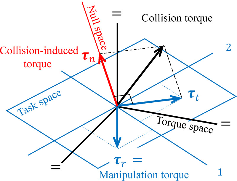
Distribution of torques in torque space
1. Introduction
In recent years, manufacturing methods have shifted from low-mix, high-volume production to high-mix, low-volume production in response to consumer trends. In high-mix, low-volume production or variable-mix, variable-volume production, frequent changes in the production line make it difficult to spend considerable time teaching robots. Therefore, collaborative robots, which can be taught in a very short time using direct teaching methods and do not require safety fences unlike industrial robots, have begun to be used in industrial fields. Although collaborative robots offer advantages, such as space-saving operation and ease of teaching, safety measures are required to ensure human protection.
The collision-processing model proposed by Haddadin et al. classifies the process into seven categories: pre-collision, detection, isolation, identification, classification, reaction, and post-collision 1. As sensorless collision-detection methods that do not require additional sensors other than joint position and current sensors, a collision-detection method using the difference between measured torque or current values and a dynamic model was proposed in 1989 2,3,4,5,6; subsequently, collision-detection methods based on changes in momentum owing to collisions were proposed 7,8,9,10,11, and collision-detection methods based on changes in power owing to collisions were proposed 12,13. A collision-detection method using deep learning was proposed in 2019 14,15, and a collision-detection method using support vector machines and autoencoders, which are machine learning techniques that do not require teaching on collision data, was proposed in 2022 16. Other methods have been proposed, such as collision detection based on changes in vibration modes by analyzing arm vibrations 17 and collision detection using particle filters 12.
Momentum-based methods have the advantage of not only detecting collisions but also identifying the link where a collision occurs. However, it is not possible to determine whether unknown manipulation forces during operation are applied to the end effector or whether collisions occur at the terminal link. Additionally, as time integration is used, a delay in collision detection may occur. Machine-learning-based methods have the advantage of not requiring a dynamic model or dynamic parameters and are robust to unknown manipulation forces during operation. However, they inherently suffer from the need to collect large amounts of training data, and if the training is inadequate, sufficient collision-detection performance cannot be achieved.
This paper proposes a sensorless collision-detection method that exploits static redundancy to achieve robustness against unknown manipulation forces and low-latency detection. This method requires no additional sensors and utilizes only the joint position and motor current sensors, which are commonly available in industrial and collaborative robots. This enables the detection of collisions at the terminal link under unknown manipulation force conditions by separating the joint driving torque into components generated exclusively by collisions and other components.
2. Collision-Detection Method
2.1. Formulation
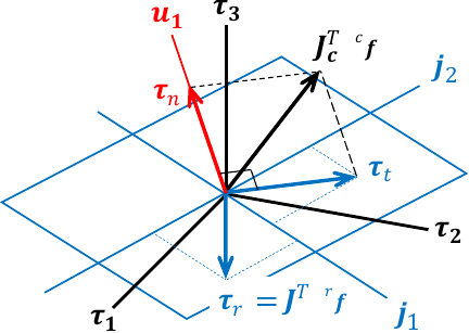
Fig. 1. Subspaces in the joint driving torque space and torque vectors generated by external forces.
The manipulator was an \(n\)-degree-of-freedom (\(n\)-DOF) serial-link manipulator that operated in an \(o\)-dimensional space with an \(m\)-dimensional workspace. The dimensional relationship satisfies either \(n \geq o > m\) or \(n > o \geq m\). The relationship between the manipulation force and joint driving torque of the manipulator can be expressed by the following static equation:
The manipulator has static redundancy because \(\boldsymbol{\tau}_r\) is an \(n\)-dimensional vector, and \({}^{r}\!\boldsymbol{f}\) is an \(m\)-dimensional vector. Therefore, Eq. \(\eqref{eq:Tau_rU003DJtFr}\) can be transformed into the following equation 18.
As the manipulator performs the manipulation using its end effector, the manipulation forces \({}^{r}\!\boldsymbol{f}\) arising from the task are applied in the task space and are generally unknown. Industrial manipulators and collaborative robots are typically equipped with joint positions and motor current sensors on each joint. The motor current is proportional to the joint driving torque, which can be accessed by external systems. Each joint of a manipulator is typically controlled by a joint position controller, and the joint position follows a given reference. Therefore, when collision forces are applied owing to contact, the manipulator may either stop owing to overload protection or continue its motion, depending on the response of the system.
As the manipulator operates under joint position control, when external forces, such as manipulation or collision forces, are applied, the manipulator is not displaced by the external forces. Instead, joint driving torques are generated to counteract the external forces, resulting in equilibrium. Therefore, the following static equation holds between the joint driving torques of the manipulator and external forces, such as the manipulation and collision forces.
2.2. Collision Detection in Limited Task Space
In industrial manipulators, the task space of an end effector is typically defined as a six-dimensional space consisting of its position and orientation. However, the manipulation forces applied to the end effector during operation do not necessarily act within the same space. For example, in a screw-tightening task, if the influence of the end effector position and orientation errors is neglected, the manipulation forces applied to the end effector lie in a two-dimensional space defined by the screw and rotational axes. Therefore, by appropriately defining the task space according to a specific task, the collision-detection performance can be improved. However, deriving Jacobian matrix \(\boldsymbol{J}\) for each task is cumbersome. Therefore, a collision-detection equation limited to the corresponding task space was derived by specifying the direction vector along which the manipulation force was applied.
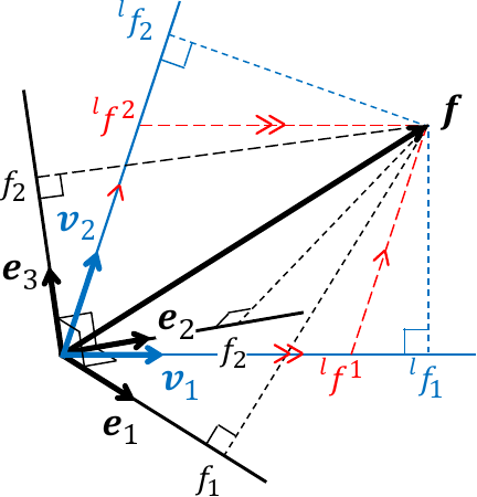
Fig. 2. Limited task space.
Let \(\boldsymbol{v}_{i} \in \mathbb{R}^{o}\) (\(i = 1, 2, \dots, m\)) denote the direction vectors along which manipulation forces are applied. The space spanned by these vectors is referred to as the limited task space. As shown in Fig. 2, the limited task space forms an oblique coordinate system. Therefore, tensor algebra is used to project the external force \(\boldsymbol{f}\) in the task space onto the limited task space. In tensor algebra, the component form of the external force \(\boldsymbol{f}\) in the task space is expressed using contravariant components, and the actual vector \(\boldsymbol{f}\) is represented as follows:
3. Simulation
In this simulation, the manipulation and collision forces were applied to a planar two-link manipulator to demonstrate that the proposed method is robust to unknown manipulation forces and can detect collisions at the terminal link, including the end effector, even outside the limited task space.
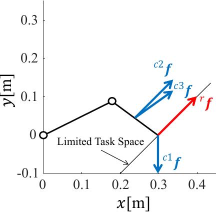
Fig. 3. Simulation on 1-redundant-DOF manipulator with a collision force \({}^{c}\!\boldsymbol{f} = [0,1]^{T}\) N and a force on end effector \({}^{r}\!\boldsymbol{f}=[1,0]^{T}\) N.
Table 1. Result of collision detection on 1-redundant-DOF manipulator.

Table 2. Specifications of xArm 6.

The manipulator used in the simulation was a planar two-link manipulator with link lengths \(l_1 = 0.2\) m and \(l_2 = 0.15\) m, as shown in Fig. 3. Each joint was assumed to be controlled by a joint position controller, such that the end effector position was maintained at \(\boldsymbol{r} = [0.3,{\ }0]^T\) m. It was assumed that the joint driving torques counteracted the external forces without causing any joint position errors, and the simulation was conducted under static conditions. The limited task space was defined by the direction vector \(\boldsymbol{v} = [1,{\ }1]^T\). A manipulation force \({}^{r}\!\boldsymbol{f} = [1,{\ }1]^T\) N was applied to the tool center point (TCP). Three collision forces were applied as follows: \({}^{c1}\!\boldsymbol{f} = [0,{\ }-1]^T\) N at the TCP and \({}^{c2}\!\boldsymbol{f} = [1,{\ }1]^T\) N and \({}^{c3}\!\boldsymbol{f} = [1,{\ }0.705]^T\) N at a point located 0.075 m from the second joint on the second link. Table 1 shows the joint torque \(\boldsymbol{\tau}\), the norm of the null-space torque \(\|\boldsymbol{\tau}_{n}\|\), and the collision-detection results with a threshold of \(\sigma = 10^{-5}\) for each applied external force, and the case where both the manipulation force \({}^{r}\!\boldsymbol{f}\) and the collision force \({}^{c1}\!\boldsymbol{f}\) are applied simultaneously.
According to Table 1, the norm of the null-space torque differs by approximately \(10^{15}\) between the case in which only the manipulation force \({}^{r}\!\boldsymbol{f}\) is applied and the cases in which the collision forces \({}^{c1}\!\boldsymbol{f}\) or \({}^{c2}\!\boldsymbol{f}\) are applied. A similar result was observed when both the manipulation force \({}^{r}\!\boldsymbol{f}\) and the collision force \({}^{c1}\!\boldsymbol{f}\) were applied, indicating that the proposed method achieved robust collision detection against manipulation forces. Moreover, although the collision force \({}^{c2}\!\boldsymbol{f}\) was applied to the terminal link in a direction parallel to the limited task space, it was successfully detected. Similarly, although the collision force \({}^{c1}\!\boldsymbol{f}\) is applied at the same TCP location as the manipulation force and in a direction different from that of the limited task space, the collision was successfully detected. However, when the collision force \({}^{c3}\!\boldsymbol{f}\) was applied, no collision was detected, although it differed only slightly in the \(y\)-axis component from the collision force \({}^{c2}\!\boldsymbol{f}\).
4. Actual Experiment
In actual experiments, collision detection is performed by applying manipulation and collision forces to the terminal link of a vertical serial-link industrial manipulator. By incorporating gravity and friction torque compensation, we demonstrated that the proposed method is applicable to real hardware.
An xArm 6 manipulator (UFactory) was used for the experiments. The main specifications of xArm 6 are listed in Table 2. xArm 6 is controlled using the ROS by sending linear motion commands to the TCP in Cartesian coordinates while the joint motor current values are measured. The joint driving torque can be obtained from the motor current values using torque constants. Therefore, following the method proposed by Gaz et al. 19, the joint driving torque counteracting the external forces was estimated by identifying and compensating for the torque constant, gravity torque parameters, and dynamic friction coefficients through preliminary experiments. In the first step, the dynamic friction coefficients were identified among the unknown parameters. The dynamic friction torque was modeled using a sigmoid function as follows:
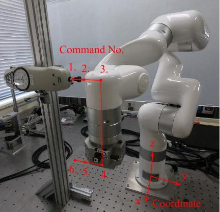
Fig. 4. Experimental environment under command No.4.
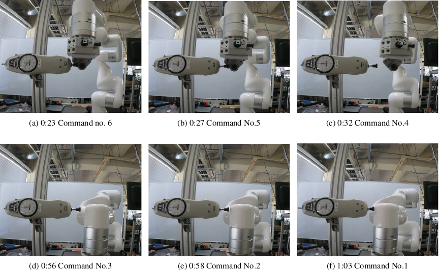
Fig. 5. Overview of the experiment.
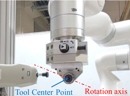
Fig. 6. End effector with \(-z\) direction of the structure where force is applied to the tool center point by a cam follower.
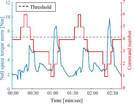
Fig. 7. Result of collision detection.
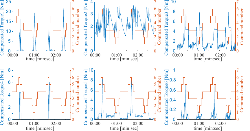
Fig. 8. Absolute value of compensated joint driving torques.
According to Fig. 7, the norm of the null-space torque reaches its maximum during the transition from command No.1 to command No.2 with a value of approximately 9 Nm. This transition from command No.1 to No.2 corresponds to the moment when the largest collision force is applied, and the norm of the null-space torque increases accordingly. However, during the transition from command No.6 to No.5, where the manipulation force applied to the end effector reaches its maximum, the norm of the null-space torque is approximately 3.5 Nm, which is smaller than the value observed when a collision force is applied. However, during command Nos.5 and 4, the norm of the null-space torque remains at approximately 6 Nm, despite the absence of external forces, indicating a relatively high value. This is likely because the gravity and dynamic friction torques cannot be fully compensated by the respective compensation methods. This was attributed to identification errors in the gravity torque parameters and dynamic friction coefficients obtained using the least-squares method. According to Fig. 8, it can be observed that, except around the transition from command No.1 to No.2 and from command No.6 to No.5 where external forces are applied to the arm, the joint driving torques counteracting external forces are small. However, residual joint driving torques of approximately 4 Nm remain, indicating that the compensation for the gravity and dynamic friction torques is imperfect. In actual production, false collision detection in the absence of real collisions reduces the productivity. Therefore, while setting conservative thresholds, it is important to avoid false detections; excessively high thresholds suppress false alarms but fail to detect minor collisions. The purpose of collision detection is to ensure the safety of collaboration with humans and to prevent damage to the robot itself and the environment. Therefore, the speed of collision detection is critical to prevent severe accidents, whereas the accuracy of collision detection using only minor collision forces is of relatively low importance. Therefore, in the experiment validation shown in Fig. 7, the collision-detection threshold was set to 7.2 Nm, corresponding to 1.2 times the maximum null-space torque norm during operations without external collision forces. This threshold suppresses false detections while preventing serious accidents, thereby enabling reliable collision detection with minimal false detections even under conditions with an unknown manipulation force.
5. Discussion
This paper proposes a sensorless collision-detection method that exploits static redundancy to achieve robustness against unknown manipulation forces and low-latency detection.
Conventional methods, such as those that directly monitor motor currents 2,3,4,5,6, and momentum-observer-based methods 7,8,9,10,11, detect collisions by comparing the joint driving torque generated in response to external collision forces with the joint torque estimated from a manipulator model. When a collision occurs, the joint torque from the base to the link, where the collision force is applied, deviates from the manipulator model, thereby enabling collision detection. However, when a collision occurs at a terminal link, the resulting deviation from the model cannot be distinguished from that caused by unknown manipulation forces, making collision detection infeasible under such conditions. The method using the power index proposed in 12,13 addresses this issue by enabling the detection of the collision location, thereby allowing discrimination between unknown manipulation forces and collision forces applied to the terminal link. Consequently, collision detection becomes feasible even under unknown manipulation force conditions. However, as time integration is used, a detection delay of approximately 40 ms occurs after the collision. Methods based on deep learning, autoencoders, and support vector machines 14,15,16 can detect collisions at the terminal link even under unknown manipulation force conditions, achieving a detection delay as low as 10 ms. However, as these methods are based on machine learning, they require a large amount of training data, and insufficient training can result in poor collision-detection performance. In contrast, the method proposed in this paper exploits static redundancy to separate the joint driving torque in a limited task space from its null-space component for collision detection. This allows the detection of collisions at the terminal link even under unknown manipulation force conditions. Moreover, as the method only monitors the joint torque components within the subspaces, the detection speed is comparable to that of conventional methods based on the direct monitoring of joint torques. In addition, as the norm of the null-space torque is computed using the Jacobian matrix of the end effector, the proposed method is computationally simple. However, as the proposed method is based on static redundancy for collision detection, it cannot be applied to tasks in which static redundancy does not exist.
In the simulation results shown in Table 1, the application of the collision force \({}^{c3}\!\boldsymbol{f}\) is labeled as “No Collision,” although a collision force is applied. This detection failure occurs because there exists a manipulation force that produces the same joint driving torque vector as that generated by the collision force \({}^{c3}\!\boldsymbol{f}\). As this manipulation force lies within a limited task space, it cannot be distinguished from manipulation forces. This phenomenon, in which different external forces produce the same torque, is analogous to the force-moment relationship, where different application points of external forces can produce the same moment. As shown in Fig. 9, when represented in the joint torque space, the joint driving torque vector \(\boldsymbol{J}_{c}^{{\,}T} {}^{c3}\!\boldsymbol{f}\) counteracting the collision force lies on the hyperplane spanned by the Jacobian \(\boldsymbol{J}_{c}^{{\,}T}\) associated with the collision point. This torque vector is decomposed into \(\boldsymbol{\tau}_t\), which lies on the hyperplane \(\boldsymbol{J}^{{\,}T} \boldsymbol{V}{\,}\boldsymbol{G}^{-1} \boldsymbol{V}^{{\,}T}\) corresponding to the limited task space, and \(\boldsymbol{\tau}_n\), which lies on the orthogonal complement \(\boldsymbol{u}_1\). However, there are cases in which the hyperplane spanned by the Jacobian \(\boldsymbol{J}_{c}^{{\,}T}\) associated with the collision point intersects with the hyperplane \(\boldsymbol{J}^{{\,}T} \boldsymbol{V}{\,}\boldsymbol{G}^{-1} \boldsymbol{V}^{{\,}T}\) corresponding to the limited task space. Therefore, when the joint driving torque vector \(\boldsymbol{J}_{c}^{{\,}T} {}^{c3}\!\boldsymbol{f}\) counteracting the collision force lies in the intersection subspace of the two hyperplanes, the distance from the limited task space (i.e., the norm of the null-space torque vector) becomes zero, resulting in collision-detection failure. In principle, these collisions cannot be detected using the proposed method. Therefore, the proposed collision-detection method must be combined with other detection methods to compensate for cases in which collisions cannot be detected using this approach alone.
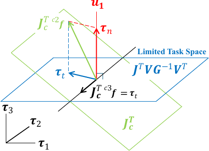
Fig. 9. Collision-detection failure condition owing to the intersection of the hyperplane spanned by the Jacobian at the collision point and that of the limited task space.
In the experimental results shown in Fig. 7, the norm of the null-space torque reaches a relatively high value of approximately 5 Nm during motion toward command No.4, where no external force is applied after the end effector separates from the force gauge following the manipulation phase. In the experiments presented in this paper, gravity and friction torque compensation was performed using parameters identified by the least-squares method to estimate the joint driving torque that counteracts the external forces applied to the manipulator. As shown in Fig. 8, the compensated joint driving torque exhibits high values during the transitions from command No.6 to No.5 and command No.1 to No.2 in the actual experimental motion. This is attributed to the reversal of the motion direction of the end effector, which results in a static friction condition. Furthermore, at approximately 25 s, where the null-space torque exhibits a high value despite no external forces being applied in Fig. 7, the compensated joint driving torque at the third joint, which counteracts the external forces, as shown in Fig. 8, also exhibits a relatively high value. These observations suggest that the performance of the proposed collision-detection method is highly dependent on the accuracy of the gravity and friction torque compensation.
6. Conclusions
This paper proposed a sensorless collision-detection method that exploits static redundancy, achieving robustness against unknown manipulation forces and a short detection delay. In addition, simulations using a planar 2-DOF manipulator and actual experiments using a vertical 6-DOF manipulator were conducted, and the following results were obtained:
-
Collisions, including those at the terminal link, could be detected even under unknown manipulation force conditions.
-
By appropriately limiting the task space according to the task, static redundancy can be introduced, enabling the application of the proposed collision-detection method.
-
In principle, collisions in which the joint torque counteracting the collision force lies within the row space of the Jacobian matrix cannot be detected using the proposed method. Therefore, it is necessary to compensate for such cases by combining this method with other collision-detection methods.
In future studies, we will combine the proposed method with other approaches to detect collisions whose counteracting torques lie within the row space of the Jacobian matrix. In addition, we plan to investigate the dynamic characteristics and extend the method to allow reliable collision detection even during high-speed motion.
Acknowledgments
This work was supported by JSPS KAKENHI Grant Number JP25K17585.
- [1] S. Haddadin, A. De Luca, and A. Albu-Schäffer, “Robot collisions: A survey on detection, isolation, and identification,” IEEE Trans. on Robotics, Vol.33, No.6, pp. 1292-1312, 2017. https://doi.org/10.1109/TRO.2017.2723903
- [2] S. Takakura, T. Murakami, and K. Ohnishi, “An approach to collision detection and recovery motion in industrial robot,” 15th Annual Conf. of IEEE Industrial Electronics Society, Vol.2, pp. 421-426, 1989. https://doi.org/10.1109/IECON.1989.69669
- [3] T. Murakami, S. Takakura, and K. Ohnishi, “Collision detection and recovery motion for industrial robot based on signal of disturbance observer,” IEEJ Trans. on Industry Applications, Vol.110, No.11, pp. 1155-1162, 1990 (in Japanese). https://doi.org/10.1541/ieejias.110.1155
- [4] K. Suita et al., “A failure-to-safety ‘Kyozon’ system with simple contact detection and stop capabilities for safe human-autonomous robot coexistence,” Proc. of 1995 IEEE Int. Conf. on Robotics and Automation, Vol.3, pp. 3089-3096, 1995. https://doi.org/10.1109/ROBOT.1995.525724
- [5] K. Kosuge, T. Matsumoto, and S. Morinaga, “Collision detection system for manipulator based on adaptive control scheme,” Trans. of the Society of Instrument and Control Engineers, Vol.39, No.6, pp. 552-558, 2003 (in Japanese). https://doi.org/10.9746/sicetr1965.39.552
- [6] S. Morinaga and K. Kosuge, “Collision detection system for manipulator based on adaptive impedance control law,” 2003 IEEE Int. Conf. on Robotics and Automation, Vol.1, pp. 1080-1085, 2003. https://doi.org/10.1109/ROBOT.2003.1241736
- [7] A. de Luca and R. Mattone, “Sensorless robot collision detection and hybrid force/motion control,” Proc. of the 2005 IEEE Int. Conf. on Robotics and Automation, pp. 999-1004, 2005. https://doi.org/10.1109/ROBOT.2005.1570247
- [8] A. De Luca, A. Albu-Schaffer, S. Haddadin, and G. Hirzinger, “Collision detection and safe reaction with the DLR-III lightweight manipulator arm,” 2006 IEEE/RSJ Int. Conf. on Intelligent Robots and Systems, pp. 1623-1630, 2006. https://doi.org/10.1109/IROS.2006.282053
- [9] J. Xiao, Q. Zhang, Y. Hong, G. Wang, and F. Zeng, “Collision detection algorithm for collaborative robots considering joint friction,” Int. J. of Advanced Robotic Systems, Vol.15, No.4, 2018. https://doi.org/10.1177/1729881418788992
- [10] L. Han, W. Xu, B. Li, and P. Kang, “Collision detection and coordinated compliance control for a dual-arm robot without force/torque sensing based on momentum observer,” IEEE/ASME Trans. on Mechatronics, Vol.24, No.5, pp. 2261-2272, 2019. https://doi.org/10.1109/TMECH.2019.2934141
- [11] S. Huang, M. Gao, L. Liu, J. Chen, and J. Zhang, “Collision detection for cobots: A back-input compensation approach,” IEEE/ASME Trans. on Mechatronics, Vol.27, No.6, pp. 4951-4962, 2022. https://doi.org/10.1109/TMECH.2022.3169084
- [12] J. Bimbo, C. Pacchierotti, N. G. Tsagarakis, and D. Prattichizzo, “Collision detection and isolation on a robot using joint torque sensing,” 2019 IEEE/RSJ Int. Conf. on Intelligent Robots and Systems, pp. 7604-7609, 2019. https://doi.org/10.1109/IROS40897.2019.8967998
- [13] Z. Qiu, R. Ozawa, and S. Ma, “Adaptive virtual power-based collision detection and isolation with link parameter estimation,” Advanced Robotics, Vol.34, No.12, pp. 814-825, 2020. https://doi.org/10.1080/01691864.2020.1751707
- [14] Y. J. Heo et al., “Collision detection for industrial collaborative robots: A deep learning approach,” IEEE Robotics and Automation Letters, Vol.4, No.2, pp. 740-746, 2019. https://doi.org/10.1109/LRA.2019.2893400
- [15] K. M. Park, J. Kim, J. Park, and F. C. Park, “Learning-based real-time detection of robot collisions without joint torque sensors,” IEEE Robotics and Automation Letters, Vol.6, No.1, pp. 103-110, 2021. https://doi.org/10.1109/LRA.2020.3033269
- [16] K. M. Park, Y. Park, S. Yoon, and F. C. Park, “Collision detection for robot manipulators using unsupervised anomaly detection algorithms,” IEEE/ASME Trans. on Mechatronics, Vol.27, No.5, pp. 2841-2851, 2022. https://doi.org/10.1109/TMECH.2021.3119057
- [17] F. Min, G. Wang, and N. Liu, “Collision detection and identification on robot manipulators based on vibration analysis,” Sensors, Vol.19, No.5, Article No.1080, 2019. https://doi.org/10.3390/s19051080
- [18] K. Okabe, “Translating manipulating force polytope by dynamics on kinematical redundant manipulators,” J. of the Robotics Society of Japan, Vol.41, No.3, pp. 303-308, 2023. https://doi.org/10.7210/jrsj.41.303
- [19] C. Gaz, E. Magrini, and A. De Luca, “A model-based residual approach for human-robot collaboration during manual polishing operations,” Mechatronics, Vol.55, pp. 234-247, 2018. https://doi.org/10.1016/j.mechatronics.2018.02.014
This article is published under a Creative Commons Attribution-NoDerivatives 4.0 Internationa License.