Development Report:
Development of a Tomato Harvesting Robot: Integration of Manipulator Configuration, Recognition, and End Effector
Toru Kuga*, Toshiyuki Yokoue*, Keita Kitano*, Hiroki Asano*, and Hisashi Sugiura*,**,***

*Yanmar Holdings Co., Ltd.
2481 Umegahara, Maibara, Shiga 521-8511, Japan
**Kyushu Institute of Technology
2-4 Hibikino, Wakamatsu-ku, Kitakyushu, Fukuoka 808-0196, Japan
***Fukushima University
1 Kanayagawa, Fukushima 960-1248, Japan

This study presents a comprehensive tomato harvesting robot system addressing three critical technical aspects: 1) optimal manipulator configuration design, 2) robust environmental recognition, and 3) efficient end effector control. For the manipulator configuration design, four different mounting configurations were systematically evaluated, with the vertical configuration featuring an offset end effector achieving the highest target reachability of 97.7%. For environmental recognition, a multi-sensor system that combines RGB and depth (RGBD) cameras and light detection and ranging (LiDAR) was implemented, utilizing depth filtering to suppress outliers. The end effector integrates suction and cutting mechanisms, employing a suction pad with conforming motion and Bowden cable-driven scissors. A bunch model was developed based on actual fruit bunches to create a testing environment with diversity and reproducibility. Field experiments conducted in a commercial greenhouse demonstrated continuous harvesting operations with a 68% suction success rate and a 45% overall harvesting success rate across 159 target fruits from 200 bunches. Additionally, the fruit position distribution in the field was measured, which can be utilized for layout optimization. This study contributes to advancing practical agricultural robotics by providing validated solutions for the three fundamental challenges in robotic crop manipulation.
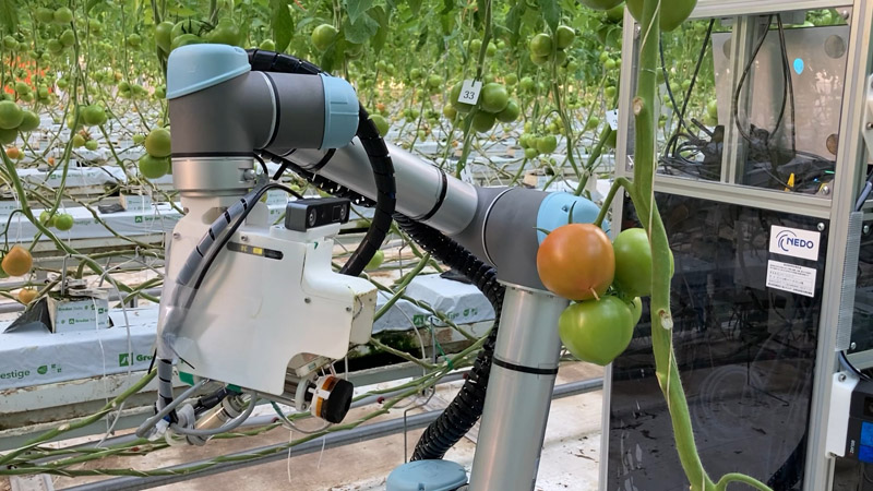
Developed tomato harvesting robot
1. Background
1.1. Current State of Agriculture
Japanese agriculture is facing complex structural challenges. The first is the issue of human resources. Japan’s agricultural workforce decreased by approximately 39% in the 15 years from 2005–2020, with approximately 70% of the remaining workers aged 65 years or older 1. This decline and aging population does not simply mean a labor shortage; it represents a structural risk that leads to disruptions in business succession and skill transfer, affecting the maintenance of regional production systems and distribution infrastructure.
Secondly, there are several environmental challenges. The International Labor Organization (ILO) predicts that global warming will reduce outdoor working hours by 2.2% in the shade and up to 3.8% in direct sunlight 2. The frequent occurrence of heat waves, heavy rain, and droughts introduces uncertainty into both work safety and process planning.
Third, there are exogenous shocks from geopolitical and market factors. The number of interstate conflicts in 2024 was the highest since 1946 3, exposing global logistics, materials, and energy supplies to intermittent disruptions. From a food security perspective, Japan’s food self-sufficiency rate of 38% on a calorie basis and approximately 60% on a production value basis is particularly problematic 4. Items with high import dependency and overseas procurement of fertilizers and feed are highly susceptible to fluctuations in exchange rates, maritime shipping costs, and raw material prices, leading to increased costs for agricultural management. Furthermore, labor shortages increase both fixed and variable costs, incentivizing the postponement of machinery upgrades and downsizing of operations.
Against this backdrop, automation and labor-saving technologies are not merely labor substitutes but fundamental investments that contribute to fulfilling safety obligations, ensuring a business continuity plan (BCP), improving quality consistency, and strengthening export competitiveness. However, a decline in skilled workers leads to a loss of tacit knowledge, increasing the difficulty of the standardization, proceduralization, and parameterization required for digital implementation. To bridge this gap, the Japanese government, led by the Ministry of Agriculture, Forestry, and Fisheries (MAFF), is promoting initiatives such as the Smart Agriculture Promotion Comprehensive Package, development of next-generation agricultural support services, demonstration projects, technology development, the “Measures for Achievement of Decarbonization and Resilience with Innovation (MIDORI) Food System Strategy,” and the “Act on the Promotion of Development and Introduction of Smart Agricultural Technologies” 5,6,7,8,9,10. These initiatives aim to lower the barriers to adoption in the field through subsidies, institutional design, and standard development.
1.2. Current State of Crop Manipulation
In contrast to the successful automation of machinery in agriculture, such as autonomous tractors 11,12,13,14,15,16,17,18 and drones 19,20,21, the field of “crop manipulation,” tasks performed by human hands such as harvesting, deleafing, de-budding, and training, has shown slow progress in mechanization, with commercialization proving even more difficult. This is due to the variability of target objects, the non-uniformity of the environment, and the delicacy of contact-based operations.
In industrial robotics, it is possible to “prepare” target objects using line arrangements and jigs. However, agricultural crops are inconsistent in shape, pose, firmness, and surface properties and are subject to seasonality and narrow optimal harvesting windows. For non-perennial crops, the period available for experimentation is limited, making reproducible evaluations challenging. Furthermore, the cultivation methods and arrangements of trellises and wires vary from farm to farm. An aging workforce, which discourages investment and leads to a small market size, also creates barriers to profitability 22,23,24,25.
Although various operations in greenhouse horticulture, such as climate control, irrigation, and nutrient management, have been progressively automated, harvesting remains largely dependent on manual labor. Quantitative studies have indicated that harvesting accounts for a substantial proportion of the total labor input in tomato production systems. Wang et al. 26 reported that harvesting alone represents approximately 50% of the total labor demand in greenhouse tomato cultivation, whereas a detailed work-time analysis under organized production conditions showed that harvesting still accounts for approximately 24% of the total working time 27. These results suggest that harvesting constitutes the primary bottleneck toward the realization of unmanned crop production in greenhouse environments. Therefore, in this study, tomato harvesting was selected as a representative high-impact crop manipulation task.
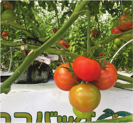
Fig. 1. Bunch of beefsteak tomatoes.
2. Tomato Harvesting Robot
2.1. Why Tomato Harvesting?
Harvesting is one of the most labor-intensive tasks in crop manipulation, making its analysis essential for advancing agricultural automation. To accelerate the implementation, conditions similar to those used in industrial robotics are preferable. Therefore, this study focused on tomatoes, which have a relatively large global market and are cultivated year-round except during the brief growing period after transplanting. This study focused on the Venlo-style greenhouse system, which is common in the Netherlands. In the Venlo system, cultivation management is systematized to facilitate human labor and efficiently increase the yield, making harvesting easier. This system has been widely adopted in large-scale farms in Japan, providing a viable market for harvesting robots.
2.2. Examples and Challenges of Tomato Harvesting Robots
Various tomato harvesting robots have been developed and studied 28,29,30,31. Recent trends include improved recognition accuracy based on deep learning (e.g., YOLO series 31), the use of multi-view cameras and semantic processing for enhanced precision, increased flexibility and adaptability of gripper designs, and the verification of practical utility through implementation and evaluation in real-world greenhouse environments. However, in addition to improving the recognition performance and trajectory generation, future social implementation requires evaluation of the harvesting robot as an integrated system, complete with functionalities from harvesting and movement to fruit storage.
Regarding the characteristics and conventional challenges of harvesting large tomatoes, as shown in Fig. 1, beefsteak tomatoes grow in dense clusters of approximately four fruits. As tomato fruits within the same cluster often exhibit different maturity levels, selective harvesting based on fruit ripeness is required. This heterogeneity in the growth state increases the complexity of harvesting operations because the target fruit must be accessed without disturbing the surrounding unripe fruits or plant structures. Fujinaga et al. 32 analyzed tomato growth states for automated harvesting and showed that variations in fruit maturity within a cluster pose a fundamental challenge to automated harvesting systems, even in structured greenhouse environments.
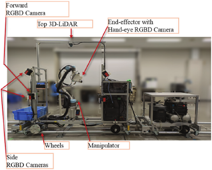
Fig. 2. System configuration of the prototype harvesting robot.
In Japan, soft-fleshed varieties intended for raw consumption in salads are mainstream and require selective harvesting of only ripe fruits. Therefore, harvesting a single target fruit from a dense cluster is difficult from both recognition and operational standpoints. Obstacles, such as leaves and stems, significantly complicate fruit recognition in greenhouse environments. Ikeda et al. 33 demonstrated that overlapping leaves and stems frequently occlude tomato fruits, causing substantial degradation in the recognition performance of harvesting robots, and highlighted the necessity of perception methods that are robust to such occlusions.
In this study, these challenges were analytically divided into separate issues, which were subsequently integrated into a single harvesting robot system: 1) designing a manipulator layout to improve workability, 2) developing a method to reduce errors in environmental recognition using a depth camera, and 3) creating an end effector with a suction mechanism to accommodate errors. These components were then integrated into the proposed system and its performance was evaluated.
The remainder of this paper is structured as follows: Section 3 introduces the proposed robot system. Section 4 describes the three improvement efforts and results, which are the novelties of this study. Section 5 describes the environment and results of the harvesting test of the entire robot. Section 6 discusses the challenges. Finally, Section 7 provides the conclusion.
Table 1. Sensor specifications.

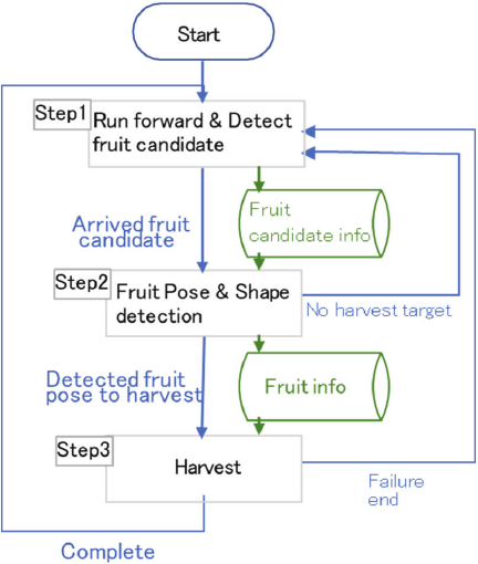
Fig. 3. General operational flowchart.
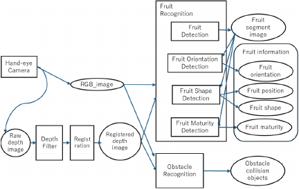
Fig. 4. Recognition flow overview. Squares represent processes and ovals represent data.
3. Overview of Tomato Harvesting Robot
3.1. System Overview
The prototype system configuration is shown in Fig. 2. The robot has wheels running on iron pipe rails that were already laid in the greenhouse. The left side of Fig. 2 show the forward direction of the robot. On the right side of the image, a cart carrying batteries and other equipment is attached to the rear of the vehicle. A collaborative robot (cobot) manipulator is installed inside the chassis frame of the robot, and an end effector and a hand-eye camera are mounted at the tip of the manipulator. A forward-facing front camera is installed in front of the chassis frame. Multiple cameras are installed on each side of the chassis frame. Side cameras are installed facing the working area on the side of the manipulator. A light detection and ranging (LiDAR) device is installed facing downward on top of the chassis frame. The specifications of each sensor are listed in Table 1. Each camera is an RGB and depth (RGBD) camera. Depth sensing methods include time of flight (ToF) and stereoscopy. The hand-eye camera provides the highest accuracy and reliability. The system identifies fruits using multiple cameras and confirms the pose with hand-eye camera before harvesting. The control system was built using robot operating system (ROS), and the manipulator is controlled using MoveIt.
3.2. Harvesting Operation Sequence
A general workflow of the operation is shown in Fig. 3.
-
Step 1)
The robot moves forward with its wheels while searching for fruits using the forward camera. If a fruit is found, its position is recorded as a fruit candidate. The wheel stops when the robot arrives at the fruit candidate location.
-
Step 2)
The manipulator extends to a pose where the fruit candidate position is visible to the hand-eye camera. The fruit candidate position is also visible from the side cameras. Cameras are used to capture images. Images are processed to detect the fruits. The detection process is described in detail later. If the fruit detection is successful, the resulting pose and shape of the fruits are recorded as the “fruit information.”
-
Step 3)
The manipulator extends to a pose where the end effector can harvest the fruit. The end effector grabs the fruit using a suction pad and cuts the peduncle. If cutting succeeds, the manipulator moves the end effector above the container, as indicated by the blue box on the left in Fig. 2. The end effector then releases the suction and drops the fruit. That completes the sequencing cycle.
3.3. Recognition Process
The outline of the recognition flow is shown in Fig. 4. This section describes the processing of images taken with the “hand-eye camera.” The processing of the other cameras is a reduced version of this procedure. The “hand-eye camera” outputs RGB and depth images.
The “raw depth image” from the camera is converted to RGB camera coordinates through the registration process. This obtains the pixel depth corresponding to the RGB pixels. The resulting image is called the “registered depth image.”
The “fruit recognition” process first performs instance segmentation as “fruit detection” to classify fruit regions in the image as the “fruit segment image.” The “fruit segment image” and the “registered depth image” are passed to the “fruit orientation detection,” “fruit shape detection,” and “fruit maturity detection” processes, and the “fruit orientation,” “fruit position,” “fruit shape,” and “fruit maturity” are calculated, respectively. These are the contents of the “fruit information.”
“Obstacle recognition” receives RGB and depth images and generates obstacle information. “Obstacle recognition” first performs semantic segmentation on an RGB image to determine obstacle regions. The obstacle areas include tomato stems, leaves, and equipment such as growing mats. A point cloud of obstacles is generated from the obstacle and depth images. The generated point cloud is input into a voxel grid filter to reduce the number of points. A sphere is placed as an obstacle at each point in the reduced point cloud. This places real-world obstacles in the MoveIt path-planning space. If flying pixels exist in the depth image as shown in Fig. 11(a) (in Section 4.2), an imaginary obstacle is created, narrowing the operating space and leading to path generation failure.
4. Technological Contributions of the Proposed System
4.1. Mechanical Design: Manipulator Layout
4.1.1. Manipulator and End Effector Placement
Multiple layouts (mounting arrangements of the vehicle body, manipulator, and end effector) of robotic systems have been reported. Many studies on harvesting robots have evaluated their performance, most of which are based on the results of actual tests, such as the harvesting success rate and speed 25,34,35,36,37, and few have discussed design optimization. Manipulability 38 is a classic indicator that is used to evaluate the quality of robotic manipulator layouts. Several similar indices have been proposed 39,40.
Manipulability is an index that is evaluated at individual positions and postures, calculated over the target work range and used to determine the design through optimization. When harvesting fruits, it is necessary to adopt a variety of working postures to handle crops with large variations in posture. Therefore, the optimal layout of the harvesting robot is not trivial. Although the calculation of evaluation indices such as manipulability is useful, it is not sufficient to prioritize work areas based on the frequency of actual work. Examples of design optimization include 41,42. In 41, optimization was performed using the index covering the set work range and the actual working posture.
In this study, as in 41, harvesting postures (end effector postures) created from actual target fruits were collected and optimization was used to determine the arm placement and end effector attachment that could cover as many postures as possible.
The reachable workspace varies significantly depending on the position and angle at which the manipulator and end effector are connected, necessitating a design choice that corresponds to the desired workspace. This study considered a “Universal Robot (UR)-type” manipulator, which is an articulated manipulator as shown in Fig. 5, with mirror symmetry, as shown in Fig. 8 (in Section 4.1.2), to investigate the optimal arrangement. Cobot manipulators including the UR series have the following design conventions. The link arrangement and axis configuration are shown in Fig. 5, and many of their joints can rotate by more than 360° (for five axes other than the Elbow). The upper arm and forearm links are offset, allowing the Elbow to bend in the forward and backward directions. The three consecutive joint axes, the Shoulder, Elbow, and Wrist1, are parallel. The Wrist (W) 1–3 axes have a basic posture of three orthogonal axes, and when W2 \(=\) 90°, the W1 and W3 axes become parallel, forming a singular configuration that must be avoided.
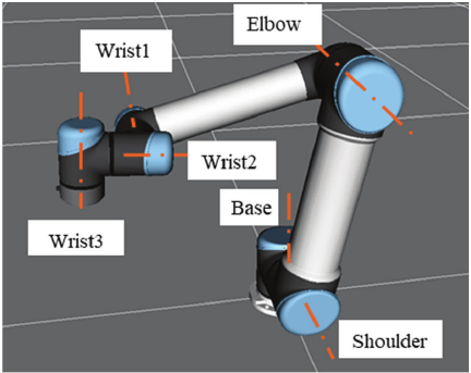
Fig. 5. Configuration and axis names of the Universal Robots UR series manipulator.
Four mounting configuration candidates were selected and their achievable rates for the target harvesting poses were compared to determine the best arrangement (Fig. 6). Based on the shape and dimensions of the end effector and the shape of the manipulator tip, four layout concepts were manually designed with the intention of having less overlap and interference between the end effector and the manipulator, while maintaining a compact outline to enable a wide range of motion. The base mounting surface was fixed horizontally or vertically for ease of manufacturing.
Type O is a vertical configuration, which is the arrangement originally used in the prototype. The suction pad and W3 axes are coaxial, and the Base axis is placed vertically. While it is easy to perform a roll motion (rotation along the pad axis), yaw \(=\pm 90°\) are singular configurations. Thus, it is not suitable for postures that require wrapping around from the left or right of the fruit, and singular regions or joint limits often appear in the middle of the path, requiring detours and resulting in non-smooth movements.
Type A is another vertical configuration, in which the W3 axis is connected in the \(+z\) direction on top of the end effector, and the Base axis is vertical. The W3 axis and end effector are offset in the axial direction, and the entire end effector is ahead of the W3 flange surface, allowing W3 to rotate by 360° without self-interference. As W3 is responsible for the yaw motion, this configuration has high freedom in the yaw direction, making it easy to wrap around the left and right sides of the fruit.
Type B is the third vertical configuration, where the W3 axis is connected in the \(+z\) direction behind the end effector. The difference from Type A is that the positional relationship between the end effector and the W3 axis has been changed from vertical to horizontal, reducing the thickness in the \(z\) direction and allowing it to reach a slightly higher position than Type A. By contrast, a 360° rotation around W3 is not possible.
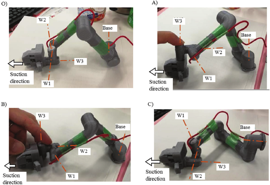
Fig. 6. Compared manipulator configurations (O, A, B, C), shown using miniature model of the manipulator.
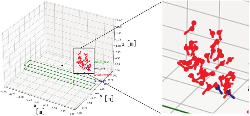
Fig. 7. 3D plot showing the target poses of the 43 fruits used for evaluation. The black vertical bar represents the manipulator base. The target poses, shown in red and blue, are represented by a sphere indicating the position and line segments indicating the peduncle and suction direction. The green frame represents the chassis shape, where interference with the manipulator is prohibited.
Type C is a “pseudo-SCARA” (SCARA: selective compliance assembly robot arm) configuration, where the Base axis is oriented horizontally and wall-mounted, and the Shoulder, Elbow, and W1 axes are generally oriented in the \(z\) direction. The suction pad axis is coaxial with the W3 axis, providing the highest degree of freedom for rolling.
To tune the manipulator base position and end effector mounting angle of each candidate, parameter optimization was performed with reference to the fruit pose list (Fig. 7) consisting of 43 sets of end effector positions and orientations. The poses were obtained from field measurements as described later. In this study, 43 working poses were treated as representatives of the standard tomato cultivation environment in terms of their distribution and range. Each layout defined by the parameters was evaluated based on the success rate of reaching the poses in the simulation. In the simulation, path planning for the target poses was performed using MoveIt, which is equal to the actual robot control system. The four layout concepts were compared based on the maximized success rate after optimization. For optimization, a parameter search tool (MLflow 43 \(+\) Optuna 44) that operates in Bayesian optimization was used. Six parameters were optimized: the manipulator base position \(x\), \(y\), \(z\); position \(x\), \(y\); and the pitch angle of the end effector from the manipulator end. This evaluation consisted of 43 path planning processes for each parameter combination, which resulted in a relatively large computational load. Bayesian optimization enables an efficient search for a good set from among a huge number of parameter combinations inside specified parameter range. Bayesian optimization generates and updates the prediction model based on past evaluation results, and selects a promising next candidate.
Optimization was performed for each of the four types. The optimization cycle was stopped after approximately 200 cycles, where the results stopped improving. The test results are listed in Table 2. Type A was the best method.
Table 2. Target pose reachability rate for each manipulator configuration type.

The reason for the superiority of Type A is that the singular posture is in the region of pitch \(\approx 90°\), and highly tilted fruits requiring such a posture are rare and thus not a significant problem (this is common to Types B and C). Type A was able to handle fruits of various orientations due to the ease of movement in the yaw direction. UR-type arms are primarily used for picking and placing in factories; in such cases, they are often used with the end effector mounted downwards in a configuration equivalent to Type A to grasp the workpiece from above. As this was a similar usage case, there were few defects. For example, since the tip W3 is the yaw axis, infinite rotation of the yaw axis is possible, making it easy to adapt to a wide range of workpiece orientations.
Type B had slightly inferior results compared with Type A. As the end effector and joints W2 and W1 overlap in the \(z\)-axis direction, it is difficult to move the yaw angle of the end effector by more than 90°. It is suggested that this has caused inferiority, because some of the fruits facing sideways require a large yaw rotation for access.
Regarding Type C, it is suggested that the reason for the inferior result is the working positions being far from the base in the \(z\) direction. In such situations, rotation of the Base causes the Shoulder and Elbow to deviate from the near-vertical position, resulting in a configuration that no longer corresponds to a pseudo-SCARA arrangement and approaches a singular configuration. This interpretation has also been applied in previous studies. In 25, the mounting of the manipulator and end effector corresponded to Type C; however, the range of operation was expanded by adding a Lift axis in the \(z\) direction, thereby overcoming the weakness of Type C mentioned previously. However, there was an increase in cost due to the additional axis.
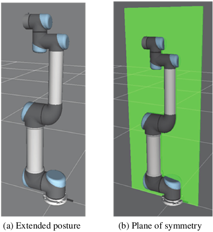
Fig. 8. Symmetry of a UR-type manipulator.
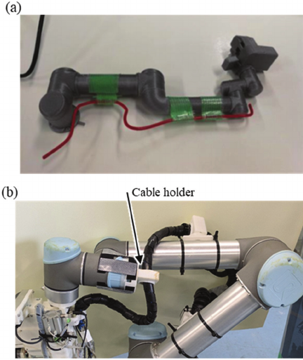
Fig. 9. Cable routing method. (a) Straight section: cables are fixed to the manipulator along the plane of symmetry. (b) Wrist section: a cable holder installed on the W2 axis holds the cables.
4.1.2. Cable Routing
Many cobots, including the UR series, have symmetrical shapes and ranges of joint motions. From the extended posture shown in Fig. 8(a), the robot can move equally to the front and back with the plane of symmetry shown in Fig. 8(b) as the boundary. Some joints (such as the Shoulder) have a symmetrical posture angle that is not 0° in the product; however, for the sake of simplicity, this study describes it based on the symmetrical posture. Despite this symmetry, typical manipulator layouts adopt an asymmetrical cable routing, as shown in Supplementary a, which loses symmetry and narrows the range of motion.
To take advantage of the symmetry, a manipulator configuration that can move symmetrically was adopted. Specifically, the paths for the cables and air tubes leading to the end effector were set within the symmetry plane, as shown in Fig. 9(a), to maintain the symmetry of the manipulator. Around the three wrist axes, as shown in Fig. 9(b), an arrangement that has a low risk of interfering with the manipulator and does not restrict its movement was realized by preparing cables (black) along the W1–W3 axes with lengths corresponding to the maximum rotation angle of each joint, and by providing a cable holder (made of white plastic) that can rotate and slide the cable freely on the intermediate W2 axis. As the W2 axis cable holder is in the opposite direction to the 0° direction of the end effector, it does not interfere, except in the extreme case of yaw \(=180°\). Furthermore, the manipulator control system was configured to move equally using the front and back sides, allowing the Elbow and other joints to rotate evenly. In addition, a multi-stage search method was adopted for the inverse kinematics solution, initially limiting the search range to the vicinity of the current position and expanding it if no solution was found. Through these measures, for situations where the wrist part obstructs the target end effector posture, it was possible for the path search to find a working posture that resolved the interference by bending the Elbow in the opposite direction and flipping the manipulator. During the harvesting tests, a path that inverted the Elbow according to the position of the target fruit was created, and there were no cable problems around the Elbow. Although the cables around the wrist were not taut, the problem of occasional pinching between the links remained.
4.2. Outlier Removal from Depth Image
Depth images generated by depth cameras have several common issues, such as noise, flying pixels, missing data, wavy errors, and insufficient resolution, regardless of the camera model. In response to these issues, median filters have traditionally been used to suppress noise 45. A bilateral filter was used to effectively reduce short-period wavy errors 45. In addition, super-resolution processing and artificial intelligence-based prediction are being developed to improve the resolution and fill in missing data. For flying pixels that create fictitious distance points between close and far objects, methods have been proposed to remove them by combining them with color images 45,46,47,48; however, combining the judgments of the two types of images increases the required calculations. The Point Cloud Library, which handles 3D point clouds, implements a function to remove outlier points that are far from the surrounding points (see 49 and Supplementary b); however, the amount of calculations required is large because it requires a large number of 3D point-to-point distances. In this study, depth was used to detect the shape of the fruit and the surrounding environment, as shown in Fig. 4. Therefore, fictitious points were treated as fictitious obstacles that caused path planning failures. However, there is a small problem if some points are thinned out from fruits or environmental shapes that contain a large number of points. Therefore, it would be effective to prioritize the removal of fictitious points and filter the depth images using a simple algorithm. Previous research has been computationally intensive partly because that it has attempted to estimate and improve depth values from fictitious depth 46,47,48. However, in this study, the approach was simplified by suppressing only the outliers.
In the proposed algorithm to suppress flying pixels, the input depth image was processed using a depth filter that invalidated distance values that were significantly different from their surroundings. A standard deviation of \(3\times 3\) pixels, centered on the target pixel, was used to measure the difference. If the calculated standard deviation exceeded a threshold value, the depth of the target pixel was rewritten as an invalid value. The behavior of the algorithm was tested by varying the threshold. The test results are shown in Figs. 10 and 11. Fig. 10 shows a cylinder with a diameter of 60 mm placed in front of the camera. The cylinder was red, the floor brown, and the rest of the background white. In Figs. 10(b) and (c), without the depth filter, flying pixels occurred within a range of approximately 100 mm behind the cylinder, connecting the cylinder to the background. The standard deviation threshold was tested in the range 2–40 mm. As in Fig. 10(d) with a 10 mm threshold or larger, almost no points were removed. At a threshold of 4 mm as shown in Fig. 10(e), the fictitious points disappeared, as did parts of the floor and walls. However, this was local and was judged to be acceptable for environmental detection. At a threshold of 2 mm as shown in Fig. 10(f), the wide areas of the floor and walls disappeared, and were close to the size of end effector. Therefore, a threshold of 4 mm was used. Figs. 11(a) and (b) show an example of an application to images from tomato harvesting, where numerous flying pixels extending far from the fruit have been removed. The camera captured from the left side. The appearance of the center of the tomato protruding towards the camera is an error originating from the characteristics of the depth data of the camera, which was not addressed in this study. This depth filter enables a more accurate capture of the fruit and its surrounding shapes, facilitating efficient path planning. Further quantitative analyses of the impact on harvest rates and adaptive thresholding are required. In addition, the filter threshold was implemented as a constant value, which is better changed depending on the distance and camera resolution; however, this is yet to be verified.
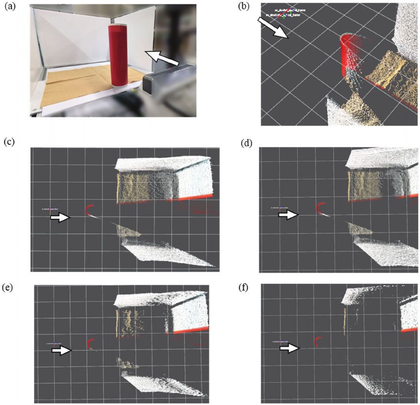
Fig. 10. Images with and without the depth filter. (a) Test setup. The camera in the foreground captured the cylinder and white background in front. The bottom surface was brown. (b) The point cloud viewed from an angle above, with the camera shooting from the top left. (c) Top view of the cylinder processed without the depth filter. (d)–(f) Top view of the cylinder processed with the depth filter of thresholds 10, 4, and 2 mm, respectively. The grid size was 100 mm. The cylinder diameter was 60 mm. The arrows indicate the camera position and capturing direction.
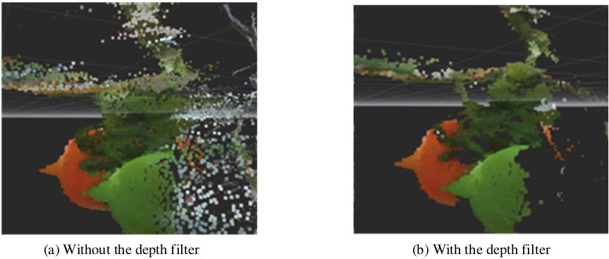
Fig. 11. Comparison of tomatoes processed with and without the depth filter.
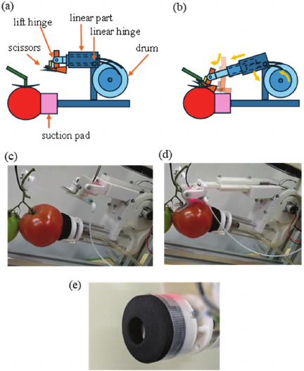
Fig. 12. End-effector overview (a) Layout. (b) Scissors expansion. (c)–(d) Test scene. (e) Trun-cone pad.
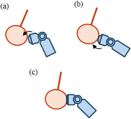
Fig. 13. Suction conforming motion example. The initial position of the suction pad is misaligned down from the center of fruit. (a) The pad swings down but does not fit to the fruit surface. (b) The pad swings up and fits to fruit surface, resulting in a suctioned state (c).
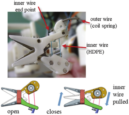
Fig. 14. Scissors driving unit.
4.3. End Effector
An end effector was developed that combines the suction and cutting mechanisms 50. As shown in Figs. 12(a)–(d), after attaching to a fruit with a suction pad, a pair of scissors on a telescopic structure extends, inserts into the peduncle, and cuts it. The fruits were then suctioned.
The “trun-cone pad” previously developed in 51 has a protruding suction port at the front, making it easy to attach the suction surface to various objects (Fig. 12(e)). This allows it to suction the fruit onto the vine with little reaction force. However, if the angle between the suction and fruit surface is large, a tight seal cannot be formed, and suction fails. As the surface tends to tilt due to variations in fruit shape and errors in the suction position, a “conforming motion” was introduced that tilts the suction pad to align the surfaces (Fig. 13). Specifically, with the center of the suction surface as the center of rotation, the angle was sequentially tilted in all directions to match the surface of the fruit and achieve successful suction. Theoretically, assuming a tomato is a sphere with a diameter of 60 mm, a conforming motion that tilts by 20° can expand the allowable error between the suction pad axis and the central axis of the fruit by \(\pm 10\) mm. It is important that the conforming motion is centered on the suction pad surface; if the motion is centered on the wrist axis, the suction cup will swing around, which pushes the fruit away and decreases the number of successes.
Many end effectors with a cutting method that incorporates scissors have been proposed, and the actuator tends to be larger than the scissors owing to the force required to cut tomatoes (approximately 100 N). Consequently, the end effector becomes several times larger than the scissors alone, making it difficult to rotate according to the orientation of the fruit. In response, a drive system is proposed that separates the scissors and actuator 50. The cutting unit uses a Bowden cable, with a combination of high-density polyethylene (HDPE) thread and a metal spring, to drive the scissors (Fig. 14). Although HDPE is weak against contact with sharp corners, it is protected by the combination with the outer coil spring and does not hit sharp corners. The friction between the HDPE and the smooth coil surface was low, increasing the drive efficiency without lubricants. Polymer threads continue to stretch under continuous tension 52, but the time required to close the scissors for cutting is short; therefore, this is unlikely to be a problem. In the experiment, an inner wire made of HDPE with a thickness of No.6 (tensile strength of 400 N) was used that could stably transmit a tension of 100 N. The driving force was doubled using a pulley on the back of the scissors, closing with a force of 200 N. No thread breakage occurred, even after multiple tests. When using a metal inner wire, it has a high bending stiffness to withstand the same tension, and the pulley diameter needs to be approximately three times larger owing to the limitation of the minimum bending radius, which is not suitable for miniaturization.
5. Experiments
5.1. Experimental Environment
The evaluation was conducted in three stages: 1) the design was verified in Gazebo simulation, 2) repeated evaluations were conducted in a mock environment, and 3) the performance was confirmed in a real field.
5.1.1. Mock Environment
In real-world experiments, performance can vary greatly owing to factors that are difficult to control, such as season, weather, and crop growth, making it difficult to maintain evaluation consistency. Therefore, a mock environment (bunch models) was created for long-term identical testing. To reproduce the individual differences and diversity of the bunches, a thermoplastic resin that softens at 40° was bent along real branches to replicate the shape of the bunches (Fig. 15). Commercially available fruit models were used to construct the mock environment. As the target fruit for the robot, the ripest fruit in the original bunch was colored red in the model, and the other fruits were green. The bunches to be modeled were selected such that the number of fruits, length of the branches, position of the target fruit, orientation of the calyx, front-back position with other fruits, and the main stem were dispersed. For the main stem model, a \(\phi 10\) mm air tube was used, and the connection between the bunch and the main stem was made with a magnet at the base, allowing for quick replacement. As the branches of the model could not be cut, the evaluation was based on the criterion that harvesting was successful when scissors were inserted into the peduncle.
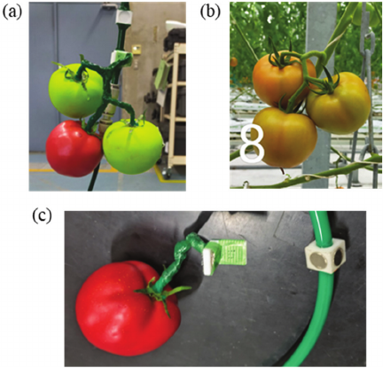
Fig. 15. Example of a bunch model. (a) Model. (b) Original bunch. (c) Magnetic joint.
A total of 50 bunch models were created. Of these, 21 models with different fruit numbers and branch length configurations were selected as the test set and used to evaluate the harvesting operation. Evaluation tests using this set showed that the harvest success rate improved from 24% at the beginning to 71% at the end of development. The success rate for each bunch revealed the following trends in the factors that determine harvesting difficulty: a) the greater the number of fruits, the greater the difficulty; and b) the harder it is to see the calyx, the greater the difficulty because the fruit orientation is uncertain.
5.1.2. Real Environment: Distribution of Harvest Target
The distribution range of the target fruits was measured in the field. Fig. 16 shows a photograph of the entrance of a lane in the field towards the back, and Fig. 17 shows a plot of the position of the fruits in a plane perpendicular to the lane. As shown in Fig. 16, the coordinate system has the \(y\)-axis at the center of the row and the \(z\)-axis originating from the top surface of the hot water pipe, which serves as the rail on which the robot runs. The fruit ranged between 370–620 mm in the \(y\) direction and 190–880 mm in the \(z\) direction. Based on this, a fruit map was created to evaluate the achievable rates.
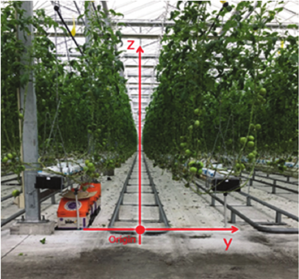
Fig. 16. View inside a greenhouse lane.
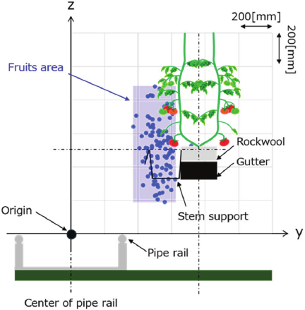
Fig. 17. Fruit distribution chart.
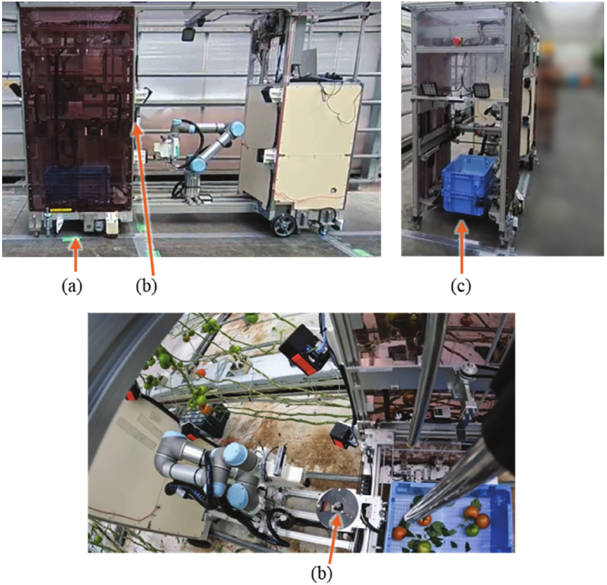
Fig. 18. Storage mechanism. (a) Container storage unit. (b) Tomato transfer unit. (c) Stored container stack.
5.1.3. Storage
To store the harvested fruits, a storage system was created that takes stackable containers into the vehicle body and sequentially places the harvested tomatoes in these containers (Fig. 18(a)). When the robot manipulator places the harvested fruit into the transfer unit (Fig. 18(b)), the transfer unit moves back and forth, left and right above the container (Fig. 18(c)), and sequentially drops it into the designated positions. When one layer of the container is full, it switches to the next layer and begins filling it. This enabled continuous harvesting.
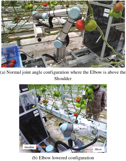
Fig. 19. Harvesting test.
5.2. Experimental Results
The designed harvesting motion was confirmed in simulation as stage 1. Insertion of scissors were confirmed in the model bunches as stage 2. Continuous harvesting in the field was achieved as stage 3. The test results are shown in Fig. 19. In the target field, 159 harvestable fruit were collected from 200 bunches. The average rate of detecting and successfully suctioning the fruit was 68%, and the overall average harvest success rate, including cutting and retrieval, was 45%.
Owing to the symmetry of the cables and the optimized layout, it was possible to position the robot with its Elbow down and look up at the target fruit, as shown in Fig. 19(b), thereby expanding the range of operations for recognition and harvesting.
The results of the suction-conforming motion are listed in Table 3 for a breakdown of 100 suction movements. Conforming improved the success rate by 7% and reduced the failure rate by 24%. The remaining suction failures were mainly caused by factors other than positional errors, such as the placement of the suction cup over the peduncle. This result is a comprehensive combination of factors, such as sensor and manipulator position errors and fruit shape variety, and is not determined by conforming alone.
Table 3. Suction results in the harvesting experiment.

6. Discussion
6.1. Analysis of Failure Factors
Suction failures are mainly caused by the suction pad not reaching the fruit owing to position estimation errors, end effector position errors, and undetected obstacles. Harvesting failures are due to scissors not capturing the peduncle because of pose estimation errors, inability to reach because of obstruction by surrounding fruits and branches, and erroneous detection of cutting. In general, failure occurs when the relationship among the (1) manipulator mounting/movement error, (2) recognition error, and (3) end effector tolerance becomes (1) \(+\) (2) \(>\) (3). Furthermore, although the push-in structure above the scissors can detect the capture of the peduncle, the deviation vector (in which direction and by how much it is missed) when it misses a branch is not obtained, making it difficult to perform effective retries.
6.2. Future Work
-
(i)
Enhanced feedback: Selecting the approach direction with a smaller error based on the measurement direction, back-estimation of the peduncle direction from minute forces and velocities during contact through the addition of proximity, tactile, and force sensors, and increasing the reliability of the cutting judgment by learning to discriminate the scissor opening/closing force waveform.
-
(ii)
Interference-resistant path planning: Utilizing the yaw freedom of Type A to select the entry angle based on the geometry of the positional relationship between the main stem and bunch and the orientation of the fruit.
-
(iii)
Robust perception and feedback: Quantitative evaluation and adaptive optimization of depth-filtering thresholds to handle varying lighting and distances.
-
(iv)
Standardization on the cultivation side: Unifying the workspace shape and improving the work speed by regulating the tree shape and clarifying the aisle width and obstacle placement.
-
(v)
Safety requirements: Establishing safety requirements that are not currently specified for agricultural robots, by referring to general standards.
7. Conclusion
This study optimized three elements of the mechanical configuration, environmental recognition, and end effector for tomato harvesting, before integrating and verifying them in a real field. The Type A manipulator layout had the best reachability rate. Recognition robustness was improved through a multi-stage sensor system and outlier suppression, and reliable harvesting performance was achieved with a suction and cutting end effector. Continuous harvesting was realized in a real field, with a suction success rate of 68% and a harvest success rate of 45%. The use of a mock environment based on real crops enabled consistent performance monitoring and continuous improvement. This helped to identify the cause of the difficulty, which depended on the number of fruits and the visibility of the calyx.
Future work will include the detection and correction of error amounts, designing intrusion paths that are resistant to interference, standardization on the cultivation side, and the application and achievement of safety standards. With these improvements, a further increase in the harvest success rate and reduction in operating costs are expected.
Acknowledgments
This research was supported by the “Innovative Robotics R&D Infrastructure Development Project” of the New Energy and Industrial Technology Development Organization (NEDO) and the Development and Improvement Program of Strategic Smart Agricultural Technology Grants (JPJ011397) from the Project of the Bio-oriented Technology Research Advancement Institution (BRAIN).
- [1] Ministry of Agriculture, Forestry and Fisheries of Japan (MAFF), “Annual report on food, agriculture and rural areas in Japan FY2021 (Summary),” 2022.
- [2] International Labour Organization (ILO), “Working on a warmer planet: The impact of heat stress on labour productivity and decent work,” 2019.
- [3] S. A. Rustad, “Conflict Trends: A global overview, 1946–2024,” PRIO Paper, Oslo: Peace Research Institute Oslo (PRIO), 2025.
- [4] Ministry of Agriculture, Forestry and Fisheries (MAFF), “Annual report on food, agriculture and rural areas in Japan FY2023,” 2024.
- [5] Ministry of Agriculture, Forestry and Fisheries (MAFF), “Promotion of smart agriculture,” 2025.
- [6] Ministry of Agriculture, Forestry and Fisheries (MAFF), “Promotion of smart agriculture,” 2020.
- [7] T. Saito, A. Shinjyo, M. Wada, M.Ishihara, and S. Hayashi, “Agricultural Data Collaboration Platform: WAGRI-System Structure and Operation,” Food and Fertilizer Technology Center for the Asian and Pacific Region (FFTC-AP), 2019. https://doi.org/10.56669/TIWC5797
- [8] Ministry of Agriculture, Forestry and Fisheries (MAFF), “Strategy for sustainable food systems, MIDORI,” Policy summary, 2021.
- [9] Japanese Law Translation Office, Government of Japan, “Outline of the act on the promotion of the development and introduction of smart agricultural technologies,” 2024.
- [10] Food and Agriculture Organization of the United Nations (FAO), International Fund for Agricultural Development (IFAD), the United Nations Children’s Fund (UNICEF), World Food Programme (WFP), World Health Organization (WHO), “The State of Food Security and Nutrition in the World 2025,” p. 234, 2025.
- [11] J. F. Reid, Q. Zhang, N. Noguchi, and M. Dickson, “Agricultural automatic guidance research in North America,” Computers and Electronics in Agriculture, Vol.25, Issues 1-2, pp. 155-167, 2000. https://doi.org/10.1016/S0168-1699(99)00061-7
- [12] M. Kise, N. Noguchi, K. Ishii, and H. Terao, “Development of the Agricultural Autonomous Tractor with an RTK-GPS and a Fog,” IFAC Proc. Volumes, Vol.34, No.19, pp. 99-104, 2001. https://doi.org/10.1016/S1474-6670(17)33120-8
- [13] D. M. Bevly, J. C. Gerdes, and B. W. Parkinson, “A new yaw dynamic model for improved high speed control of a farm tractor,” J. of Dynamic Systems, Measurement, and Control, Vol.124, No.4, pp. 659-667, 2002. https://doi.org/10.1115/1.1515329
- [14] R. Takai, O. Barawid Jr., and N. Noguchi, “Autonomous navigation system of crawler-type robot tractor,” IFAC Proc. Volumes, Vol.44, Issue 1, pp. 14165-14169, 2011. https://doi.org/10.3182/20110828-6-IT-1002.03355
- [15] N. Noguchi and O. C. Barawid Jr., “Robot farming system using multiple robot tractors in Japan,” IFAC Proc. Volumes, Vol.44, Issue 1, pp. 633-637, 2011. https://doi.org/10.3182/20110828-6-IT-1002.03838
- [16] R. Takai, L. Yang, and N. Noguchi, “Development of a crawler-type robot tractor using RTK-GPS and IMU,” Engineering in Agriculture, Environment and Food, Vol.7, Issue 4, pp. 143-147, 2014. https://doi.org/10.1016/j.eaef.2014.08.004
- [17] M. O’Connor, T. Bell, G. Elkaim, and B. Parkinson, “Automatic Steering of Farm Vehicles Using GPS,” Proc. of the Third Int. Conf. on Precision Agriculture, pp. 767-777, 1996. https://doi.org/10.2134/1996.precisionagproc3.c91
- [18] Y. Nagasaka, N. Umeda, Y. Kanetai, K. Taniwaki, and Y. Sasaki, “Autonomous guidance for rice transplanting using global positioning and gyroscopes,” Computers and Electronics in Agriculture, Vol.43, Issue 3, pp. 223-234, 2004. https://doi.org/10.1016/j.compag.2004.01.005
- [19] C. Zhang and J. M. Kovacs, “The application of small unmanned aerial systems for precision agriculture: A review,” Precision Agriculture, Vol.13, No.6, pp. 693-712, 2012. https://doi.org/10.1007/s11119-012-9274-5
- [20] W. H. Maes and K. Steppe, “Perspectives for remote sensing with unmanned aerial vehicles in precision agriculture,” Trends in Plant Science, Vol.24, Issue 2, pp. 152-164, 2019. https://doi.org/10.1016/j.tplants.2018.11.007
- [21] H. Aasen, E. Honkavaara, A. Lucieer, and P. J. Zarco-Tejada, “Quantitative remote sensing at ultra-high resolution with UAV spectroscopy: A review of sensor technology, measurement procedures, and data correction workflows,” Remote Sensing, Vol.10, Issue 7, Article No.1091, 2018. https://doi.org/10.3390/rs10071091
- [22] G. Kootstra, X. Wang, P. M. Blok, J. Hemming, and E. van Henten, “Selective harvesting robotics: Current research, trends, and future directions,” Current Robotics Reports, Vol.2, No.1, pp. 95-104, 2021. https://doi.org/10.1007/s43154-020-00034-1
- [23] C. W. Bac, E. J. van Henten, J. Hemming, and Y. Edan, “Harvesting robots for high-value crops: State-of-the-art review and challenges ahead,” J. of Field Robotics, Vol.31, Issue 6, pp. 888-911, 2014. https://doi.org/10.1002/rob.21525
- [24] E. J. van Henten, J. Hemming, B. A. J. van Tuijl, J. G. Kornet, J. Meuleman, J. Bontsema, and E. A. van Os, “An autonomous robot for harvesting cucumbers in greenhouses,” Autonomous Robots, Vol.13, No.3, pp. 241-258, 2002. https://doi.org/10.1023/A:1020568125418
- [25] C. Lehnert, A. English, C. McCool, A. W. Tow, and T. Perez, “Autonomous Sweet Pepper Harvesting for Protected Cropping Systems,” IEEE Robotics and Automation Letters, Vol.2, No.2, pp. 872-879, 2017. https://doi.org/10.1109/LRA.2017.2655622
- [26] T. Wang, W. Du, L. Zeng, L. Su, Y. Zhao, F. Gu, L. Liu, and Q. Chi, “Design and testing of an end-effector for tomato picking,” Agronomy, Vol.13, Issue 3, Article No.947, 2023. https://doi.org/10.3390/agronomy13030947
- [27] T. Kuroda, M. Yamamoto, and H. Saito, “Accuracy assessment of tomato harvest working time predictions,” Agriculture, Vol.14, Issue 12, Article No.2257, 2024. https://doi.org/10.3390/agriculture14122257
- [28] T. Yoshida, T. Fukao, and T. Hasegawa, “Fast detection of tomato peduncle using point cloud with a harvesting robot,” J. Robot. Mechatron., Vol.30, No.2, pp. 180-186, 2018. https://doi.org/10.20965/jrm.2018.p0180
- [29] S. Oda, R. Fukumoto, K. Hirata, S. Tahara, K. Yoshida, S. Yasukawa, and K. Ishii, “Development of a tomato harvesting robot for farm field,” Proc. of Int. Conf. on Artificial Life and Robotics, Vol.28, pp. 479-483, 2023. https://doi.org/10.5954/ICAROB.2023.OS20-4
- [30] K. Koe, P. K. Shah, B. Walt, J. Westphal, S. Marri, S. Kamtikar et al., “Precision harvesting in cluttered environments: Integrating end effector design with dual camera perception,” arXiv preprint, arXiv:2501.19395, 2025. https://doi.org/10.48550/arXiv.2501.19395
- [31] J. Redmon, S. Divvala, R. Girshick, and A. Farhadi, “You only look once: Unified, real-time object detection,” Proc. of the IEEE Conf. on Computer Vision and Pattern Recognition (CVPR), pp. 779-788, 2016. https://doi.org/10.1109/CVPR.2016.91
- [32] T. Fujinaga, S. Yasukawa, and K. Ishii, “Tomato Growth State Map for the Automation of Monitoring and Harvesting,” J. Robot. Mechatron., Vol.32, No.6, pp. 1279-1291, 2020. https://doi.org/10.20965/jrm.2020.p1279
- [33] T. Ikeda, R. Fukuzaki, M. Sato, S. Furuno, and F. Nagata, “Tomato Recognition for Harvesting Robots Considering Overlapping Leaves and Stems,” J. Robot. Mechatron., Vol.33, No.6, pp. 1274-1283, 2021. https://doi.org/10.20965/jrm.2021.p1274
- [34] J. Davidson, S. Bhusal, C. Mo, M. Karkee, and Q. Zhang, “Robotic manipulation for specialty crop harvesting: A review of manipulator and end-effector technologies,” Global J. of Agricultural and Allied Sciences, Vol.2, No.1, pp. 25-41, 2020. https://doi.org/10.35251/gjaas.2020.004
- [35] Q. Pan, D. Wang, J. Lian, Y. Dong, and C. Qiu, “Development of an automatic sweet pepper harvesting robot and experimental evaluation,” 2024 IEEE Int. Conf. on Robotics and Automation (ICRA), 2024. https://doi.org/10.1109/ICRA57147.2024.10610866
- [36] V. Bloch, A. Bechar, and A. Degani, “Fitness of diverse orchard architectures on optimal robot manipulator,” IROS Workshop on Agri-Food Robotics, 2015.
- [37] B. Arad, J. Balendonck, R. Barth, O. Ben-Shahar, Y. Edan, T. Hellström, J. Hemming, P. Kurtser, O. Ringdahl, T. Tielen, and B. van Tuijl, “Development of a sweet pepper harvesting robot,” J. of Field Robotics, Vol.37, Issue 6, pp. 1027-1039, 2020. https://doi.org/10.1002/rob.21937
- [38] T. Yoshikawa, “Manipulability of Robotic Mechanisms,” The Int. J. of Robotics Research, Vol.4, No.2, pp. 3-9, 1985. https://doi.org/10.1177/027836498500400201
- [39] P. Chiacchio, S. Chiaverini, L. Sciavicco, and B. Siciliano, “Global task space manipulability ellipsoids for multiple-arm systems,” IEEE Trans. on Robotics and Automation, Vol.7, No.5, pp. 678-685, 1991. https://doi.org/10.1109/70.97880
- [40] C. Gosselin and J. Angeles, “A global performance index for the kinematic optimization of robotic manipulators,” J. of Mechanical Design, Vol.113, No.3, pp. 220-226, 1991. https://doi.org/10.1115/1.2912772
- [41] D. Guri and G. Kantor, “A systematic robot design optimization methodology with application to redundant dual-arm manipulators,” arXiv preprint, arXiv:2507.21896, 2025. https://doi.org/10.48550/arXiv.2507.21896
- [42] A. Silwal, J. R. Davidson, M. Karkee, C. Mo, Q. Zhang, and K. Lewis, “Design, integration, and field evaluation of a robotic apple harvester,” J. of Field Robotics, Vol.34, No.6, pp. 1140-1159, 2017. https://doi.org/10.1002/rob.21715
- [43] M. Zaharia et al., “Accelerating the machine learning lifecycle with MLflow,” IEEE Data Engineering Bulletin, Vol.41, No.4, pp. 39-45, 2018.
- [44] T. Akiba, S. Sano, T. Yanase, T. Ohta, and M. Koyama, “Optuna: A next-generation hyperparameter optimization framework,” Proc. of the 25th ACM SIGKDD Int. Conf. on Knowledge Discovery and Data Mining, pp. 2623-2631, 2019. https://doi.org/10.1145/3292500.3330701
- [45] T. Matsu, N. Fukushima, and Y. Ishibashi, “Depth map refinement with weighted cross bilateral filter,” The J. of the Institute of Image Information and Television Engineers, Vol.66, No.11, pp. 434-443, 2012 (in Japanese). https://doi.org/10.3169/itej.66.J434
- [46] E. Vasudevan, S. N. Sridhara, E. Pavez, A. Ortega, R. Singh, and S. Kalluri, “Color-guided flying pixel correction in depth images,” arXiv preprint, arXiv:2410.08084, 2024. https://doi.org/10.48550/arXiv.2410.08084
- [47] T. Schairer, B. Huhle, P. Jenke, and W. Straßer, “Parallel non-local denoising of depth maps,” Proc. of the Int. Workshop on Local and Non-Local Approximation in Image Processing (EUSIPCO Satellite Event), 2008.
- [48] Y. Song and Y.-S. Ho, “Time-of-flight image enhancement for depth map generation,” Proc. of the 2016 Asia-Pacific Signal and Information Processing Association Annual Summit and Conf. (APSIPA), 2016. https://doi.org/10.1109/APSIPA.2016.7820774
- [49] R. B. Rusu, Z. C. Marton, N. Blodow, M. Dolha, and M. Beetz, “Towards 3D point cloud based object maps for household environments,” Robotics and Autonomous Systems, Vol.56, Issue 11, pp. 927-941, 2008. https://doi.org/10.1016/j.robot.2008.08.005
- [50] T. Kuga, T. Yokoue, M. Saiki, and H. Sugiura, “A cutting-suctioning-feeding end effector for large tomato harvesting,” Proc. of the JSME The 8th Int. Conf. on Advanced Mechatronics (ICAM2024), 2024.
- [51] M. Saiki, T. Yokoue, T. Kuga, K. Kitano, and H. Sugiura, “Development of suction harvesting hand ‘Trun-cone pad’ for spherical crops,” SICE System Integration Division Annual Conf., 2021 (in Japanese).
- [52] A. Takata, G. Endo, K. Suzumori, and H. Nabae, “Basic study for drive mechanism with synthetic fiber rope – Third report: Creep testing machine and preliminary experiments –,” 2017 JSME Conf. on Robotics and Mechatronics, 2017 (in Japanese). https://doi.org/10.1299/jsmermd.2017.1P2-G07
- [a] IGUS, “Arm clamp for cobot – COB.” https://www.universal-robots.com/marketplace/products/01tP40000071NP6IAM/ [Accessed September 22, 2025]
- [b] Point Cloud Library (PCL), “pcl::StatisticalOutlierRemoval
Class Template Reference,” 2017. https://pointclouds.org/documentation/classpcl_1_1_statistical_outlier_removal.html [Accessed January 30, 2026]
This article is published under a Creative Commons Attribution-NoDerivatives 4.0 Internationa License.