Paper:
Design and Evaluation of a Two-Wheeled Weeding Robot for Paddy Fields
Hiroyuki Inoue*, Hitoshi Sori*, Masashi Sugimoto**
 , Hiroyuki Hatta***, and Yasuhiro Ando***
*National Institute of Technology, Tsuyama College
624-1 Numa, Tsuyama, Okayama 708-8509, Japan
**National Institute of Technology, Tomakomai College
443 Nishikioka, Tomakomai, Hokkaido 059-1275, Japan
***IKOMA Robotech Corporation
634-28 Toshima, Tsuyama, Okayama 708-0016, Japan

Recently, consumers have shown a high level of interest in food safety and security, as well as in reducing environmental impacts. Therefore, for rice, which is the staple food of the Japanese people, its cultivation without the use of herbicides or chemical fertilizers is desired. This paper proposes a two-wheeled weeding robot that floats on a water surface and is equipped with a movable mechanism in which large-diameter wheels contact the soil under their own weight in response to water level height and soil unevenness. The robot body was designed to float on water by placing floats on both sides and spanning the rice row, enabling it to continue moving even as the rice grows. The movable system utilizes a simple yet robust four-bar linkage, which is designed to accommodate soil adhesion. This study first clarified the design method for a four-bar linkage mechanism. Next, it experimentally investigated the effect of the angle of paddles attached to the wheels on the propulsive force. Finally, it experimentally confirmed the effectiveness of the proposed weeding robot.
Two-wheeled weeding robot for paddy fields
1. Introduction
Recently, consumer interest in food safety and security, as well as in reducing environmental impacts, has increased significantly. Consequently, demand for cultivation methods that do not use herbicides or chemical fertilizers is increasing, even for rice, which is the staple food of the Japanese people. However, weed removal is essential for rice cultivation in the absence of herbicides. Representative weeding methods include biological weed control using ducks and mechanical weed control using walk-behind and ride-on weeders. However, these methods have problems such as requiring significant care, imposing heavy labor burdens, and incurring high initial costs. Therefore, research and development are being conducted on a compact and easily portable paddy field-weeding robot that saves labor and reduces physical effort.
To address the technical challenges associated with mobile mechanisms traveling on the irregular terrain of paddy fields, various weeding robots have been proposed, including crawler 1,2,3,4, screw 5, and wheeled 6,7,8,9,10,11 types. A critical consideration when employing these robots is their susceptibility to soil surface irregularities resulting from rice paddy puddling and rice-transplanter wheel tracks. In particular, with heavier robots, mobile mechanisms tend to disturb soil surfaces, leading to locomotive failures caused by excessive slip and insufficient torque. Because these weeding robots maintain a fixed positional relationship between their mobile mechanisms and the main chassis, strict water-level management is indispensable. Furthermore, because the attitude of the robot fluctuates in response to soil-surface irregularities, careful consideration is required when identifying rice rows using image processing. The specific impacts of design parameters such as the geometry of crawlers, screws, and wheels, as well as the mounting angles of the paddles, on the propulsion performance of these robots remain largely unclarified.
Kameyama and Wada 12 proposed a compact paddy-weeding robot equipped with a mechanism that adjusts the relative position between the wheels and robot body, enabling it to travel while floating on the water surface. However, slippage or damage occurs in the gear connecting the two links that comprise this mechanism. Furthermore, because the robot moves by pushing down the rice plants, they become obstacles approximately three weeks after transplantation, making its operation difficult; consequently, alternative weeding methods are required thereafter.
This paper proposes a two-wheeled weeding robot that travels while straddling a rice row with its body floating on the water surface. First, by floating on the water surface, the proposed robot does not require to support its own weight with wheels, thereby reducing the extent to which the wheels sink into the soil. Consequently, the resistance force exerted on the wheels by the soil is reduced; therefore, the wheel diameter is increased to prevent them from falling into a depression. The wheels are attached to the robot’s body via a four-bar linkage mechanism such that they make contact with the soil under their own weight, thereby allowing vertical movement. Subsequently, the effect of the mounting angle of the paddles attached to the wheels on the propulsive force of the robot was investigated.
The first experiment involved fabricating a half-scale wheel model and examining how biomass plastic spheres, which were used as a substitute for soil, moved in response to wheel rotation. The second experiment was conducted in a simulated paddy field on campus, where one end of the rubber cord was attached to a force gauge and the other end to the robot’s body, and the robot was propelled forward to measure its thrust. Based on these two experiments, the effect of paddle mounting angle on the propulsive force of the robot was determined. Finally, the results of locomotion and weeding experiments conducted to verify the effectiveness of the proposed two-wheeled weeding robot are presented.
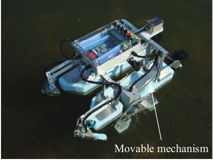
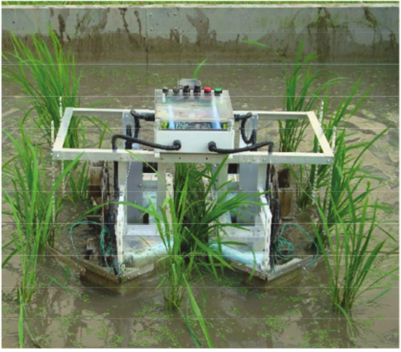
Fig. 1. Overview of two-wheeled weeding robot.
2. Weeding Robot
2.1. Structure of Weeding Robot
The proposed weeding robot is shown in Fig. 1. The robot consists of a main body and a movable wheel mechanism. It travels while straddling rice rows, with its body floating on the water surface. The robot body uses low-density polystyrene foam floats to achieve light weight and high buoyancy, and aluminum frames in sections requiring rigidity. As illustrated in Fig. 2, floats mounted on both sides of the robot body ensure lateral stability and allow travel even as the rice plants grow. Furthermore, by floating on the water surface, the position of the robot body relative to the water surface is stabilized, enabling it to maintain a consistently horizontal posture. The drive wheels are attached to the left and right frames of the robot body via a four-bar linkage mechanism and rotated using DC motors covered with waterproof casings.
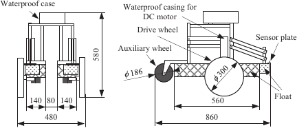
Fig. 2. Structure of two-wheeled weeding robot.
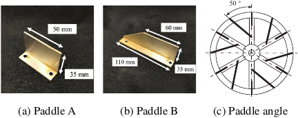
Fig. 3. Overview of the drive wheel.
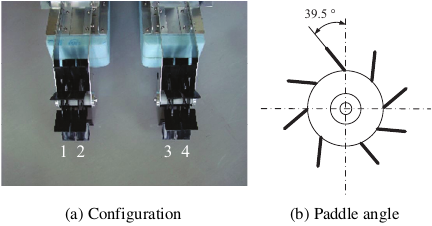
Fig. 4. Overview of the auxiliary wheel.
The drive wheel has a diameter of 300 mm and width of 38 mm and is made of an aluminum alloy. Six paddles of each type are attached to the sides of these wheels, as shown in Fig. 3(c). Paddle A measures 50 mm in length, 15 mm in width, and 35 mm in height (Fig. 3(a)), and paddle B has a top width of 60 mm, bottom width of 110 mm, thickness of 15 mm, and height of 35 mm (Fig. 3(b)). The robot moves as the wheels rotate and the paddles generate resistance from the soil. A microcontroller and two batteries enclosed in a waterproof case are mounted on the upper part of the robot. Auxiliary wheels are installed at the rear to prevent the front of the robot from lifting during movement and to enhance the water agitation. The auxiliary wheels have a diameter of 186 mm and width of 30 mm and are created from polypropylene, with two wheels paired, as shown in Fig. 4(a). Eight paddles measuring 45 mm in length, 30 mm in width, and 3 mm in thickness are attached to the circumferential surface of the wheels at an angle of 39.5°, as shown in Fig. 4(b). The specifications of the weeding robot are listed in Table 1. Two Li-Po batteries are used as the power source, allowing approximately three hours of operation on a single charge. The drive wheels are driven by independent DC motors, and their rotational speeds are controlled using pulse width modulation.
The weeding method is shown in Fig. 5. The weeding robot traverses the paddy field using its wheels to uproot weeds and agitate the soil, thereby clouding the water, blocking sunlight, and inhibiting photosynthesis to suppress weed growth.
Table 1. Specifications of weeding robot.

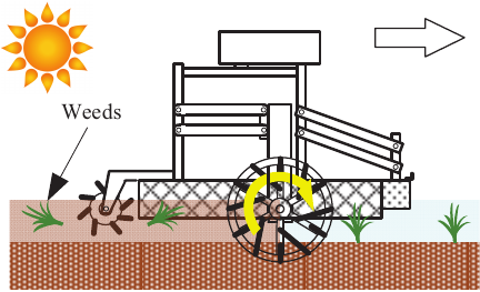
Fig. 5. Weeding method.
2.2. Design of Four-Bar Linkage Mechanism
This section describes the design procedure for a four-bar linkage mechanism, which serves as the movable mechanism of the wheel to accommodate fluctuations in the water level and soil irregularities within paddy fields. In the design, the structure is simplified to reduce the risk of damage and ensure its durability. The required function of the four-bar linkage mechanism is to maintain contact between the wheels and the soil, thereby preventing a decrease in the propulsive force and wheel idling. In paddy rice cultivation, the water level is generally maintained at 50–70 mm when the rice plants have been established. Soil unevenness in paddy fields is approximately –30 mm owing to puddling and 30–50 mm in depth owing to the wheel tracks of rice transplanters 13. Fig. 6(a) shows the variations in water level, and Fig. 6(b) shows the changes caused by soil irregularities within the paddy field. As shown in Fig. 6, the required upward travel range of the four-bar linkage mechanism is 40 mm, combining a 10 mm change in the water level and a 30 mm soil elevation. Conversely, the required downward travel range is 60 mm, combining a 10 mm change in water level and a 50 mm soil depression. Therefore, the total required range of motion is 100 mm, indicating that soil irregularities in the paddy field have a significant impact. In the design, after determining the total range of motion, 40% is allocated to upward movement and 60% to downward movement. In the present design, we allowed a margin in the required range of motion and set to 150 mm; 60 mm is allocated for upward movement and 90 mm for downward movement.
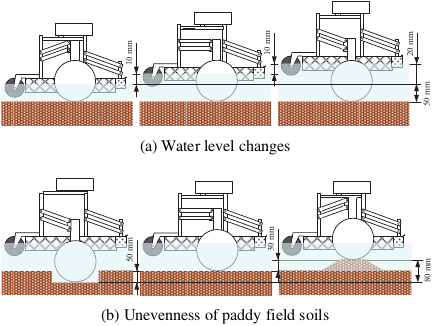
Fig. 6. Required range of four-bar linkage mechanism.
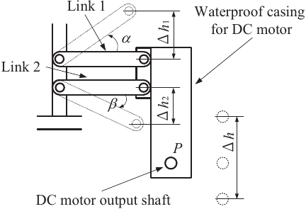
Fig. 7. Four-bar linkage model.
Figure 7 shows the model of the four-bar linkage mechanism to be designed. The horizontal positions of links 1 and 2 are used as a reference, and the lengths of the links are denoted as \(L_{1}\) and \(L_{2}\). The lengths \(L_1\) and \(L_2\) are equal and arranged in parallel. The left ends of the links are attached to the robot body frame, whereas the right ends are connected to the waterproof casing housing the DC motor. Point \(P\) corresponds to the output shaft of the DC motor to which the drive wheel is attached via a flange. With the horizontal direction as a reference, the angle of the four-bar linkage mechanism is defined as \(\alpha\) when the output shaft \(P\) moves upward and as \(\beta\) when it moves downward. The vertical displacement of the output shaft \(P\) can be determined using the following equation:
Therefore, the total range of motion of the output shaft \(P\) is given by
In the present design, with \(\Delta h=150\) mm, \(L_1=L_2=150\) mm, \(\alpha=35°\), and \(\beta=25°\), \(\Delta h_1\) is approximately 86 mm, and \(\Delta h_2\) is approximately 63 mm. A downward force of approximately 20 N, including the weights of the drive wheel, DC motor, and waterproof casing, is applied to the four-bar linkage mechanism. When a 60 mm upward travel range is set during the robot’s operation, \(\Delta h_1\) becomes \(86 - 60\) mm, and from Eq. \(\eqref{eq:1}\), \(\alpha\) is approximately 10°. Therefore, when the weeding robot is placed in the paddy field, the water level is adjusted such that \(\alpha\) is approximately 10°.
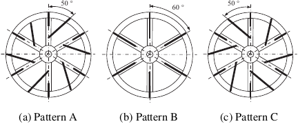
Fig. 8. Paddle mounting patterns on the drive wheels.
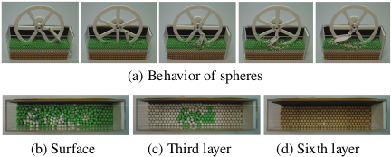
Fig. 9. Experimental results of pattern A (equipped with paddle B).
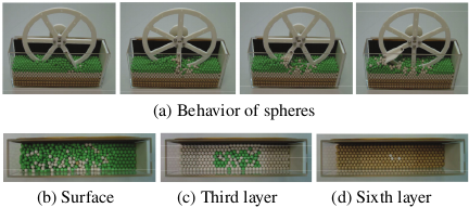
Fig. 10. Experimental results of pattern B (equipped with paddle B).
2.3. Evaluation of Drive Wheel Paddles
In this section, the effects of paddles A and B on the drive wheels and the influence of the mounting angle of paddle B are investigated. First, approximately 6 mm in diameter biomass plastic spheres of different colors were placed in a transparent case to enhance visibility, and a half-scale wheel model with paddle B mounted at three different angles, as shown in Fig. 8, was used. Figs. 9–11 show the behavior of the spheres when the wheel equipped with paddle B was rotated clockwise in 30° increments. The transparent case contained six layers of brown spheres at the bottom, three layers of green spheres in the middle, and two layers of white spheres at the top. No differences were observed in the movement of the spheres on the surface or in the third layer between patterns A and B. In pattern C, the surface on the right side was covered with green spheres, and a dense cluster of green spheres was observed at the center of the third layer. Therefore, the green spheres had moved into a relatively narrow area near the underside of the wheel. Furthermore, because the white spheres did not move into the sixth layer, we inferred that they primarily migrated toward the rear of the wheel. For pattern B, several white spheres migrated to the sixth layer. Based on the above, pattern C appeared to be the most suitable for generating propulsion because it moved the soil without dispersing it toward the rear of the wheel. However, from the perspective of soil agitation, patterns A and B appeared to be more appropriate.
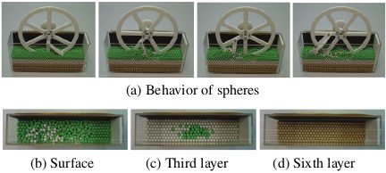
Fig. 11. Experimental results of pattern C (equipped with paddle B).
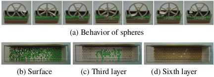
Fig. 12. Experimental results of pattern A (equipped with paddles A and B).
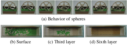
Fig. 13. Experimental results of pattern C (equipped with paddles A and B).
Figures 12 and 13 show the behavior observed when a wheel equipped with one paddle A and one paddle B was rotated clockwise at 30° intervals. In pattern B, the installation of paddle A was not feasible; therefore, this configuration was excluded from the experiment. In both patterns A and C, compared with the previous experiment, the white spheres on the surface and the green spheres in the third layer moved over a wider area. However, in pattern C, the white spheres had not moved into the sixth layer. Therefore, paddle A was considered to move the spheres over a wide area downward. Based on the above, to achieve both propulsion and soil agitation, we inferred that paddle B should be mounted in pattern C to direct the soil rearward, whereas paddle A, which provides soil agitation, should be installed.
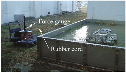
Fig. 14. Experimental setup.
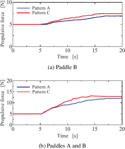
Fig. 15. Measured propulsive force.
Next, the effect of the mounting angles of paddles A and B on the propulsive force of the robot was investigated. In the experiment, paddles were mounted on the wheels of the prototype weeding robot in patterns A and C, and the robot was run through a simulated paddy field while the propulsive force was measured using a force gauge. Fig. 14 shows the experimental setup used for the measurements. The force gauge was fixed to a stand, with one end of a rubber cord attached to it and the other end connected to the robot body. The propulsive force was measured by moving the robot forward from a state in which the rubber cord was under a tension of 5 N and recording the tension when the robot stopped. The rotational speed of the wheels during weeding was approximately 10 rpm.
Figure 15(a) shows the propulsive force when six paddle Bs were mounted on the wheel, and Fig. 15(b) shows the propulsive force when six each of paddles A and B were mounted on the wheel. Fig. 15 shows that the propulsive force was greater when both types of paddles were mounted and that pattern C of the mounting angles produced a larger propulsive force than pattern A. This confirmed that the results of the present experiment exhibited a trend similar to that observed in the previous wheel model experiment. Therefore, the following experiments used a drive wheel with both types of paddles mounted in pattern C.
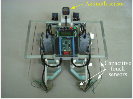
Fig. 16. Sensor system.
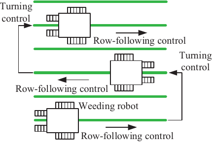
Fig. 17. Navigation route.
3. Control System
The weeding robot is equipped with a capacitive touch sensor to detect rice plants and an azimuth sensor, as shown in Fig. 16. The capacitive touch sensors are mounted as follows: two sensor plates on the floats in front of the drive wheels, and one sensor plate on each side of the robot body. When a rice plant contacts the sensor plate, the capacitance changes, causing a corresponding change in the sensor output voltage. An azimuth sensor is mounted on the rear upper section of the weeding robot. The travel path of the weeding robot is shown in Fig. 17. In previous studies, methods using image processing to identify rice rows have been proposed; however, precautions must be taken to prevent interference from sunlight reflected from the water surface 14.
In this study, the weeding robot was positioned at the edge of the paddy field, straddling the rice rows. When the start switch was pressed, the current orientation was recorded as the target heading. At the start of the operation, the robot acquired data from the front and side capacitive touch sensors. In the absence of rice plant detection by the front sensors, the trajectory correction is performed based on the deviation between the current orientation and target heading. Upon detecting a rice plant, the robot controls the DC motor duty ratio to navigate around the plant, thereby ensuring row-following control along the rice rows. If the sensor plates do not detect rice plants on either side for a certain period, the robot determines that it has reached the end of the row and initiates turning control. Regarding the operational constraints, an area of approximately 1300 mm from the levee to the edge of the rice rows must be kept free.
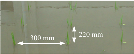
Fig. 18. Condition of the simulated paddy field.
4. Experimental Results and Consideration
To verify the effectiveness of the prototype weeding robot, we conducted experiments in a simulated paddy field on campus. Rice transplantation was performed as shown in Fig. 18, with a row spacing of 300 mm, plant spacing of 220 mm, and three seedlings per plant. For the experimental setup, a simulated paddy field measuring 4,000 mm \(\times\) 4,000 mm was partitioned into three sections: weeded, non-weeded, and performance evaluation zones. In the performance evaluation zone, rice plants were not planted at either end of the rows. The simulated paddy field was exposed to outdoor conditions including wind and rain. In the absence of a water circulation mechanism, the water level was maintained exclusively through manual supply and discharge, and no other environmental controls were applied.
Because weeding is typically performed for approximately 30–40 days until the start of mid-season drainage, the average weeding period was considered to be approximately six weeks. In the weeded zone, the first weeding test was conducted seven days after transplanting. The prototype weeding robot was scheduled to travel weekly for six weeks; however, owing to unfavorable weather conditions, the weeding period was extended to seven weeks. In the performance evaluation zone, the experiment was extended to eight weeks to demonstrate the ability of the robot to travel through mature rice plants. This duration was selected because the plant height varies significantly depending on the cultivar and environmental conditions; thus, a longer period was necessary to verify the performance against more advanced growth stages.
4.1. Travel Experiments
First, the effectiveness of the proposed four-bar linkage mechanism was evaluated. Fig. 19 illustrates the traveling conditions of the weeding robot one week after rice transplanting. The left image shows the robot traveling over the level soil, the center image shows the left wheel moving upward owing to the soil elevation, and the right image shows the right wheel moving upward.
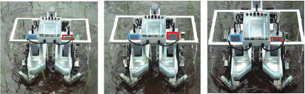
Fig. 19. Behavior of four-bar linkage mechanism.
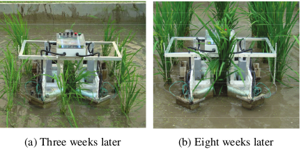
Fig. 20. Traveling motion of the weeding robot.
Subsequently, the operational period of the robot was investigated. Fig. 20(a) shows the robot traveling among the rice plants three weeks after transplanting, whereas Fig. 20(b) shows its traveling motion eight weeks after transplanting. Fig. 20(b) shows that the robot travels astride the grown rice plants. The weeding robot was designed with a high ground clearance; consequently, it can travel through rice plants even eight weeks after transplanting. In addition, as shown in Fig. 20(b), the water level was higher than that shown in Fig. 20(a); thus, both wheels moved downward. Therefore, the proposed four-bar linkage mechanism can accommodate fluctuations in the water level and soil irregularities, and it demonstrated excellent durability with no malfunctions during the experiments. We confirmed that the robot remained capable of operating even seven weeks after transplanting when weeding became necessary.
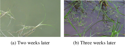
Fig. 21. Dislodged weeds.
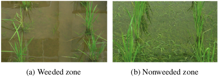
Fig. 22. State of the simulated paddy field three weeks after.
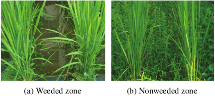
Fig. 23. State of the simulated paddy field eight weeks after.
4.2. Weeding Experiments
Figure 21(a) shows the weeds floating on the water surface two weeks after transplanting, and Fig. 21(b) shows the weeds floating three weeks after transplanting, as observed during the travel of the weeding robot. Two weeks after transplantation, the number of floating weeds was low, whereas at three weeks after transplantation, numerous weeds were observed on the water surface. Therefore, some weed suppression can be expected from water turbidity immediately after transplanting; however, weekly traveling motion alone cannot completely inhibit weed growth, highlighting the effectiveness of wheel weeding. Fig. 22 shows the state of the rice plants three weeks after transplanting, while Fig. 23 shows their condition eight weeks after transplanting. In the weeded zone, almost no weeds remained between rice rows. However, a small number of weeds remained near the rice plants, where the wheels did not pass.
Moreover, as shown in Fig. 23(a), no damage to the rice plants was observed during the robot operation. However, operating the robot during the heading stage could result in contact between the tops of the rice plants and the robot body, potentially reducing the yield and is considered potentially problematic. Therefore, we can conclude that the prototype weeding robot is effective both in dislodging weeds and agitating water.
5. Conclusion
In this study, we developed a two-wheeled weeding robot equipped with large-diameter wheels that straddles rice rows while its body floats on the water surface. By floating on the water surface, the wheels of the robot support its weight. Consequently, wheels can be designed with a large diameter, thereby preventing them from sinking into depressions. Subsequently, the design procedure for the four-bar linkage mechanism installed between the robot body and wheels is clarified, enabling the wheels to maintain continuous contact with the ground under their own weight. Subsequently, the effect of the paddle mounting angle on the propulsive force of the robot was clarified. Finally, travel and weeding experiments conducted in a simulated paddy field confirmed the effectiveness of the proposed two-wheeled weeding robot.
A future challenge is the transition from a visual assessment of water turbidity to a quantitative evaluation. To this end, we plan to investigate methods, such as image analysis using a high-speed camera.
Acknowledgments
This study was supported by JSPS KAKENHI Grant Number JP20K06331.
- [1] T. Mitsui, T. Kobayashi, T. Kagiya, A. Inaba, and S. Ooba, “Verification of a weeding robot ‘AIGAMO-ROBOT’ for paddy fields,” J. Robot. Mechatron., Vol.20, No.2, pp. 228-233, 2008. https://doi.org/10.20965/jrm.2008.p0228
- [2] S. Nakai and Y. Yamada, “Development of a weed suppression robot for rice cultivation: Weed suppression and posture control,” Int. J. of Mechanical and Mechatronics Engineering, Vol.8, No.12, pp. 1886-1890, 2014.
- [3] Q. Zhang, M. E. S. J. Chen, and B. Li, “A visual navigation algorithm for paddy field weeding robot based on image understanding,” Computers and Electronics in Agriculture, Vol.143, pp. 66-78, 2017. https://doi.org/10.1016/j.compag.2017.09.008
- [4] H. Madokoro et al., “Prototype development of small mobile robots for mallard navigation in paddy fields: Toward realizing remote farming,” Robotics, Vol.10, No.2, Article No.63, 2021. https://doi.org/10.3390/robotics10020063
- [5] K. H. Choi, S. K. Han, K.-H. Park, K.-S. Kim, and S. Kim, “Vision based guidance line extraction for autonomous weed control robot in paddy field,” 2015 IEEE Int. Conf. on Robotics and Biomimetics, pp. 831-836, 2015. https://doi.org/10.1109/ROBIO.2015.7418873
- [6] D. Fujioka, H. Inoue, H. Sori, Y. Ando, and H. Hatta, “Development of turning algorithm for autonomous weeding robot,” Mechanical Engineering Congress 2013, Session No.G151036, 2013 (in Japanese).
- [7] H. Hatta, Y. Ando, K. Iizuka, H. Inoue, and H. Sori, “Development of weeding robot for paddy field,” Mechanical Engineering Congress 2013, Session No.S151013, 2013 (in Japanese).
- [8] S, Akihira, H. Inoue, H. Sori, H. Hatta, and Y. Ando, “Weeding robot control for rice plant line following,” Proc. of the 2015 JSME Conf. on Robotics and Mechatronics, Session No.2P1-B09, 2015 (in Japanese). https://doi.org/10.1299/jsmermd.2015._2P1-B09_1
- [9] K. Namba, H. Inoue, H. Sori, H. Hatta, and Y. Ando, “Rice plant line detection using capacitive touch sensor for weeding robot,” Proc. of the 2015 JSME Conf. on Robotics and Mechatronics, Session No.2P1-B10, 2015 (in Japanese). https://doi.org/10.1299/jsmermd.2015._2P1-B10_1
- [10] H. Sori, H. Inoue, H. Hatta, and Y. Ando, “Effect for a paddy weeding robot in wet rice culture,” J. Robot. Mechatron., Vol.30, No.2, pp. 198-205, 2018. https://doi.org/10.20965/jrm.2018.p0198
- [11] J. Ju et al., “Design and experiment of an adaptive cruise weeding robot for paddy fields based on improved YOLOv5,” Computers and Electronics in Agriculture, Vol.219, Article No.108824, 2024. https://doi.org/10.1016/j.compag.2024.108824
- [12] K. Kameyama and T. Wada, “Adaptation of a small robot for paddy fields to the water depth change using variable legs,” J. Robot. Mechatron., Vol.34, No.1, pp. 159-166, 2022. https://doi.org/10.20965/jrm.2022.p0159
- [13] R. Tabatabaekoloor and M. Rezaei, “Puddling effects on the shear parameters of paddy field soil,” Agricultural J., Vol.8, No.5, pp. 217-221, 2013.
- [14] B. Chen, S. Tojo, and K. Watanabe, “Machine vision for a micro weeding robot in a paddy field,” Biosystems Engineering, Vol.85, No.4, pp. 393-404, 2003. https://doi.org/10.1016/S1537-5110(03)00078-3
This article is published under a Creative Commons Attribution-NoDerivatives 4.0 Internationa License.