Research Paper:
Toolpath Generation Based on Mathematical Algorithms with Shape Simulation for Mold Machining
Daigo Inui, Hidenori Nakatsuji, and Isamu Nishida†
Graduate School of Engineering, Kobe University
1-1 Rokkodai-cho, Nada-ku, Kobe, Hyogo 657-8501, Japan
†Corresponding author

Owing to the shortening of product life cycles and the diversification of consumer needs, the mold industry is also facing increasing demands for shorter lead times, higher quality, and lower costs in mold manufacturing. To meet these demands, automation, high-precision, and high-efficiency technologies in both the pre-processing and post-processing of mold machining are essential. This study proposes and develops a system that includes solution methods of the mathematical Traveling Salesman Problem (TSP) to generate toolpaths with suppressed redundant motions from standard triangulated language (STL)-format computer-aided design (CAD) models, which represent the surface of a three-dimensional shape as a set of triangular meshes and are independent of the type of CAD software, as input data. In the proposed system, a dexel-based workpiece simulation is conducted in parallel with toolpath analysis to identify unmachined regions remaining after pre-machining processes. By detecting these remaining removal regions and calculating efficient paths based on the TSP, the system can output toolpaths from which idle tool motions without cutting have been reduced. To verify the effectiveness of the system, two case studies are conducted using two mold CAD models. The results of the case studies show that toolpaths for both mold models are automatically generated from their STL-format CAD models. The generated toolpaths are then used for actual machining, and the results confirm that the molds have been successfully machined without any critical issues.
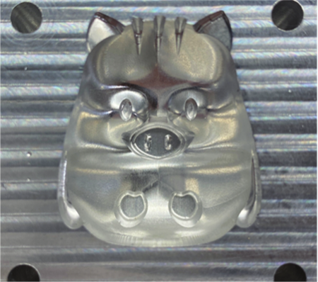
Machined results of case study
1. Introduction
Currently, there is an increasing demand for high-mix, low-volume production in the manufacturing industry. At the same time, labor shortages caused by a declining birth rate and an aging population have become significant concerns. Mold manufacturing typically requires considerable time and cost; however, low-cost and high-quality production is expected. Consequently, the implementation of automated process planning technologies has been promoted as an effective solution. Although previous studies have addressed the automatic generation of numerical control (NC) programs for mold machining 1, several challenges remain unresolved, including the insufficient consideration of redundant toolpaths and the inability to automate tool selection. In addition, a study proposed a method in which generated toolpaths were evaluated using a simulation based on a grid-point model representing workpiece geometry, thereby enabling the detection and omission of air cutting, which is defined as tool movement without material removal 2. However, this approach still has a limitation. Although the tool can rapidly move to the next cutting point while avoiding air-cutting regions, the retraction and repositioning paths themselves still constitute air cutting.
In the broader context of automated process planning, a flexible process planning method that is adaptable to changing manufacturing conditions for milling has been proposed 3. In addition, a process planning method based on machining feature recognition for a turning-milling center has been proposed 4. Furthermore, a framework for decomposing a target shape into removal volumes and recognizing machining features was proposed for both polyhedral and curved surface geometries, thereby providing a basis for shape understanding in process planning 5,6. C-space-based computer-aided process planning for freeform mold cavity machining and automated process planning for mold parts integrating feature recognition and group technology have also been reported 7,8. In contrast, as a direct toolpath generation method using standard triangulated language (STL)-format polyhedral models, a curve-based approach for three-axis machining based on a local offset has also been reported 9. These studies provide important insights into flexible process planning, feature-recognition-based process planning, shape understanding based on removal volume decomposition, process planning for freeform surface machining, automated process planning for mold parts, and direct toolpath generation from STL models. However, existing process planning studies generally assume relatively structured shape descriptions based on machining features or computer-aided design (CAD) models and therefore do not provide a framework for consistently generating multistage toolpaths for mold geometries containing many freeform surfaces using STL meshes as input. In addition, direct STL-based toolpath generation methods primarily focus on a single machining stage and do not address the tracking of the remaining removal regions between stages or the optimization of path connectivity considering such regions. Therefore, automatically generating toolpaths that suppress air cutting in a systematic manner by optimizing the path connectivity while considering the remaining removal regions across multiple machining stages using an STL-format CAD model as input remains an unresolved issue.
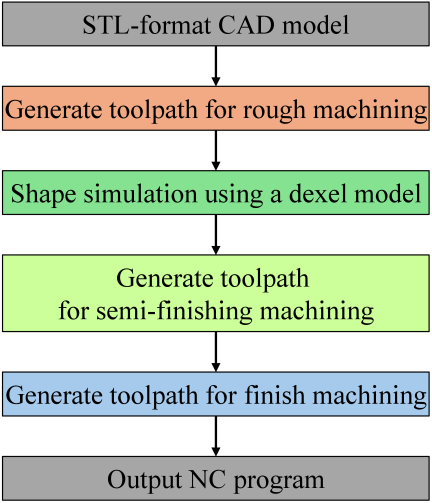
Fig. 1. Workflow of the proposed system.
This paper proposes a novel method for calculating toolpaths using an STL-format product CAD model that represents a three-dimensional shape solely with triangular meshes and is independent of any specific CAD software as input data. In the proposed method, contour lines are first extracted during rough machining from the intersection curves between the STL mesh and the \(XY\)-planes, and toolpaths suitable for mold machining are generated by applying offsetting and Boolean operations. Next, in semi-finishing, a shape simulation of the workpiece is conducted using a dexel model to identify the remaining removal regions between machining stages, and the simulation results are reflected in the toolpath generation. Furthermore, for the identified remaining removal regions, mathematical algorithms for the Traveling Salesman Problem (TSP), namely the greedy algorithm, 2-opt method, and double-bridge operation, were applied to optimize the connection order of the toolpath segments, thereby generating efficient toolpaths with reduced air cutting. Finally, scanning line toolpaths are generated based on the geometric contact relationship between the triangular mesh and the tool geometry. The overall workflow of the system is shown in Fig. 1 to clarify the relationships among the processes constituting the proposed system.
The contribution of this study does not lie in the STL-based toolpath generation itself or the use of a dexel model alone, both of which have been reported previously. Rather, the novelty lies in an integrated framework that sequentially tracks the remaining removal regions across roughing, semi-finishing, and finishing; generates process-specific toolpaths for these machining processes; and optimizes the connectivity among toolpath segments corresponding to the remaining removal regions using TSP-based algorithms. By integrating these functions into a single workflow, the proposed system enables automatic multiprocess toolpath generation from STL-format CAD models while reducing unnecessary tool motions across machining processes.
Finally, two case studies were conducted to validate the usefulness of the proposed system. Two mold models were prepared, and NC programs were automatically generated from their STL-format CAD models. Machining was then conducted using the generated tool paths, followed by mold production and casting. These steps confirmed the validity of the proposed system. The results show that the proposed framework can automatically generate practical multiprocess toolpaths for mold machining while minimizing unnecessary tool motions.
2. Toolpath Generation Based on Mathematical Algorithms for Mold Machining
In mold machining processes, such as injection molding or casting, it is necessary to remove the material from a block-shaped workpiece to form the desired product shape. Therefore, closed-pocket machining is primarily applied. In this machining method, the tool enters a confined space enclosed by the surrounding material, which requires sophisticated control to manage the approach and avoid collisions. Furthermore, the molded geometry of a product often consists of complex free-form surfaces. Consequently, conventional automated process planning methods 3,10,11,12 based on simple prismatic features or holes, the so-called machining features that represent geometrically defined regions corresponding to specific machining operations, are insufficient for handling such shapes effectively. There are also limitations to the tools used. For instance, square-end mills do not have cutting edges on the bottom face and are therefore unsuitable for plunge machining operations. In such cases, cutting loads become concentrated, thereby increasing the risk of machining defects and tool breakage. Although flat drills, which are suitable for axial cutting, have been proposed for roughing operations 13, they require machine tools with high torques to withstand the increased cutting resistance, thereby imposing additional equipment constraints. Therefore, high-feed machining has recently attracted considerable attention as a practical alternative. It minimizes the axial depth of the cut while significantly increasing the feed rate, thereby reducing the machining time. However, this approach typically involves the use of large-diameter tools for roughing and switching to smaller-diameter tools for semi-finishing and finishing. Consequently, machining between processes leads to air cutting, which reduces the overall machining efficiency. In complex geometries, these air-cut regions can become extensive, significantly affecting the total machining time. Therefore, it is essential to track the machined regions sequentially and optimize the toolpaths for each machining stage.
The following sections present the proposed approach to addressing these challenges.
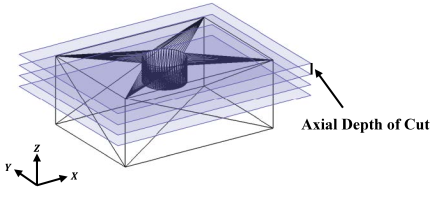
Fig. 2. Product model divided on the \(XY\)-plane at specified intervals.
2.1. Geometrical Analysis of Contour Lines to Generate Toolpath for Rough Machining
In mold machining, die-sinking operations, in which a tool plunges vertically to form deep cavities, are common. However, conventional roughing methods based on scanning lines involve frequent plunging motions that lead to increased machining time and higher cutting loads. As mentioned above, square-end mills tend to exhibit machining instability during plunging, which often necessitates a reduction in the feed rate. Moreover, from the perspective of machine tools, plunging imposes a substantial load on the spindle, which can lead to operational instability. To address these issues, this study generated a toolpath using contour-based machining instead of scanning lines, thereby reducing the plunging motion and improving machining efficiency.
First, the system extracts the contour line information from the STL-format CAD model. The contours were obtained based on the intersection between the \(XY\)-plane and the triangular mesh. They are represented as one or more closed curves describing the product geometry within each plane. As shown in Fig. 2, the STL CAD data were divided along the \(XY\)-planes at \(Z\)-intervals, determined by the axial depth of the cut specified in the machining conditions. Next, for each divided \(XY\)-plane, the intersections between the plane and each triangular mesh were geometrically extracted. The line segments where the triangular mesh plane intersects the \(XY\)-plane are identified and connected if they share the same start and end points, as shown in Fig. 3. Fig. 4 shows the contour line obtained by connecting the raw intersection segments between the triangular meshes and the divided \(XY\)-plane. Because STL meshes are generally non-uniform, the extracted segment lengths are also non-uniform: flat regions tend to be represented by long segments, whereas curved regions tend to be represented by multiple short segments. If such long segments are used directly, the spatial resolution may become insufficient for the subsequent offsetting, Boolean operations, and toolpath generation. Therefore, when the length of an intersection segment exceeds the supported resolution, interpolated points are inserted along the segment, as illustrated in Fig. 5. Thus, sufficient resolution can be maintained in the subsequent geometric operations. In contrast, when the segment length is shorter than the supported resolution, the original endpoints are retained without modification. Through this procedure, contour information can be successfully extracted from STL-format CAD data 14.
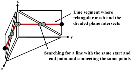
Fig. 3. Geometrical relationship between the triangular mesh and the divided plane.
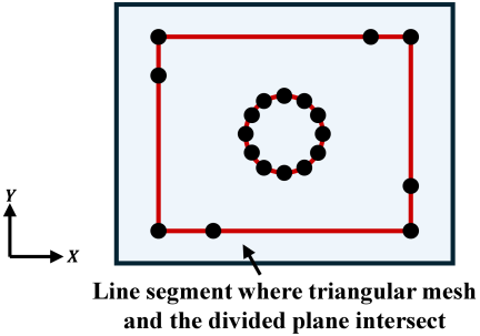
Fig. 4. Contour line obtained by connecting the intersection segments between the triangular meshes and the divided \(XY\)-plane.
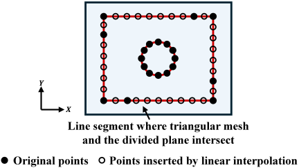
Fig. 5. Addition of linearly interpolated points to long intersection segments to satisfy the required resolution for subsequent geometric operations.
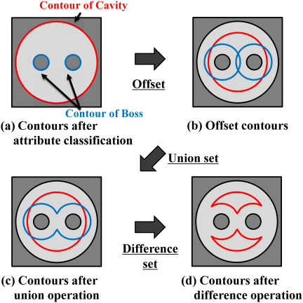
Fig. 6. Contours for toolpath generation after offsetting, union, and difference operations.
Based on the concavity and convexity of the shape, the extracted contour is classified: contours representing concave regions are identified as “Cavity,” while those representing convex regions are identified as “Boss.” As shown in Fig. 6, the system offsets the contours while considering the tool radius and machining allowance. Specifically, the Cavity contours are offset inward, and the Boss contours are offset outward by an amount corresponding to the sum of the tool radius and machining allowance (Fig. 6(b)). After the offsetting operation, if the Cavity or Boss contours overlap or contact each other, a union operation is performed for each attribute group to unify the contours. This ensures a consistent organization of contours based on their attributes (Fig. 6(c)). Subsequently, if intersections exist between the Cavity and Boss contours, a difference operation is performed to subtract the Boss from Cavity. This operation eliminates overlapping and contacting regions across all contours, enabling the construction of nonredundant, well-defined contours (Fig. 6(d)). Consequently, even in cases involving complex overlaps or intersections among multiple contours, geometric consistency can be maintained. Furthermore, if the difference operation results in a Cavity that is not entirely enclosed by a Boss or is not completely eliminated, the system recursively adds the radial depth of cut (i.e., the tool-radius-direction offset amount) for the current machining condition to the previous offset amount and repeats the offset and Boolean operations. This enables the consistent extraction of contours that comprehensively cover the machining region on the \(XY\)-plane. The entire process begins at the top surface of the workpiece and is applied stepwise to each \(XY\)-plane according to the axial depth of the cut. In other words, by applying the offset and Boolean operations to each \(Z\)-slice plane, the system constructs contours that define the overall three-dimensional machining region.
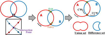
Fig. 7. Entry/exit classification and contour traversal in the Greiner–Hormann algorithm.
The union and difference operations used in this process are based on the Greiner–Hormann algorithm. As shown in Fig. 7, the Greiner–Hormann algorithm constructs a connection structure between two simple polygons by detecting intersections and inserting them into their corresponding polygon edges. In this algorithm, when the contour of polygon A, in which the vertices are arranged counterclockwise, is taken as the reference, each intersection point on A’s contour is classified as either an “entry” or an “exit” based on the location of the next vertex. If the next vertex lies inside polygon B, in which the vertices are arranged counterclockwise, the intersection is marked as an entry point; if it lies outside, it is marked as an exit point. In the union operation, the resulting contour is generated by first traversing polygon B from the entry point counterclockwise until it reaches the exit point. The traversal then switches to polygon A, continuing in a counterclockwise direction and returning to the original entry point. Conversely, in the difference operation, the contour is generated by first traversing polygon B from the entry point clockwise until it reaches the exit point. The traversal then switches to polygon A and continues counterclockwise and then back to the entry point. If multiple entry–exit point pairs exist, this procedure is repeated for each pair 15,16. All contours obtained through this series of operations are then used as toolpaths and outputted as NC programs.
2.2. Toolpath Optimization for Remaining Removal Regions Using TSP-Based Algorithms
To improve machining efficiency, adopting a multiprocess approach that uses multiple cutting tools of different diameters for roughing and semi-finishing is effective. Initially, a large-diameter tool was used to efficiently remove material over a wide region, followed by a small-diameter tool for the precise machining of the remaining regions. This approach enables a reduction in the total machining time while maintaining high machining accuracy. However, during the semi-finishing process, a key challenge arises from air cutting, in which the tool travels through regions that have already been removed during roughing. Avoiding such redundant machining is essential for optimizing semi-finishing operations. To address this issue, the system analyzes the tool path in conjunction with shape simulation using the dexel model. This allows the system to compute the tool path for different tool diameters while excluding regions where air cutting would occur. The dexel model is a representation method in which a 3D shape is divided into uniformly spaced grid cells on the \(XY\)-plane, and each cell records the depth information along the \(Z\)-axis as a continuous value 17,18. This simplified structure, which focuses solely on the \(Z\)-direction in space, significantly reduces the amount of data to be processed, making it suitable for the efficient analysis of shape changes during each machining process. First, the regions remaining after roughing were represented using the dexel model. The geometric relationship between the tool and dexel cells during interference is shown in Fig. 8. When updating the dexel, the \(Z\)-coordinate of the spherical surface at the tip of the ball-end mill was calculated and replaced using the following equation:
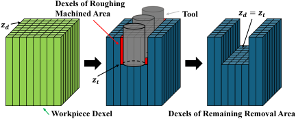
Fig. 8. Geometric relationship between the tool and the dexel model.
At this stage, exhaustive geometric calculations must be conducted between all discretely represented dexels and the point set representing the current tool positions. Because the roughing toolpath computed in the previous section is represented as a discrete set of tool position points, the number of tool positions is extremely large. In addition, the number of dexels representing the workpiece shape increases with analysis resolution. However, this approach inherently involves a massive number of repetitive computations, resulting in significant computational inefficiency.
To address this issue, the present study implements parallel computation using a graphics processing unit (GPU), which was originally designed for graphics rendering but has recently been exploited as a highly effective platform for general-purpose parallel processing. Interference detection between each tool position and dexel can be conducted independently, as each tool position is analyzed in the same manner to determine the dexels that interfere with the tool and update their height values. In this approach, all the dexel data, along with the \(X\)-, \(Y\)-, and \(Z\)-coordinates of each tool position and tool radius, are first transferred to the GPU memory. Each GPU core then performs interference judgment with the dexels and calculates the updated \(Z\)-values of the interfered dexels. The computed results are subsequently transferred to the CPU, thereby achieving parallel processing.
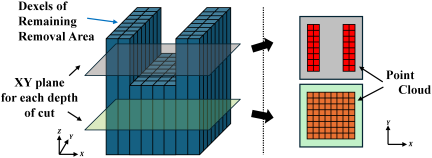
Fig. 9. Extraction of remaining material regions on the \(XY\)-plane at each axial depth.
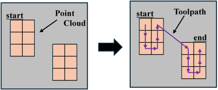
Fig. 10. Toolpath generation using the greedy algorithm.
Although the \(Z\)-values of the dexels after interference detection may differ among different tool positions, the minimum \(Z\)-value for each dexel was adopted as a valid one. Through this parallel interference computation between the tool and dexels using the GPU, the analysis time can be significantly reduced.
Next, as shown in Fig. 9, the system extracts the remaining material regions in the target \(Z\)-coordinate as a point cloud based on the dexel. The extracted point cloud represents the uncut regions according to the resolution of the dexel model. If the toolpath is calculated to pass through all of these points, as described later, and the tool radius is larger than the spatial resolution, the material removal rate will be substantially lower than the tool’s maximum capacity. Therefore, the point cloud was filtered and reconstructed based on the tool radius. This process prevents the generation of redundant toolpaths caused by overly dense points relative to the tool size, thereby enabling the generation of an efficient toolpath that reflects the tool characteristics.
To generate a toolpath that passes through the resulting point cloud without omissions, this study adopted a greedy algorithm. This algorithm is an approximate solution of the TSP. As shown in Fig. 10, the greedy algorithm constructs a toolpath by sequentially selecting the nearest unvisited point from the current position and moving it to that point. This method aims to form an overall path efficiently by repeatedly making locally optimal choices at each step. The TSP is an NP-hard problem, and obtaining an exact solution requires an enormous amount of computation. In contrast, the greedy algorithm offers the advantage of the computational complexity of \(O(n^2)\). This is because for a point set of size \(n\), the algorithm constructs a path by calculating the distances to all the remaining points at each iteration. Owing to its relatively low computational cost and ease of implementation, the greedy algorithm is considered an effective approach for generating an initial toolpath 19. Using this method, the point cloud can be reordered to generate a feasible toolpath. However, the result is an approximate solution and is not guaranteed to be optimal.
To improve the tool path obtained by the greedy algorithm, the 2-opt method, which is a local search (LS) technique, was adopted. This method is based on an improvement strategy, in which two edges in the initial path are selected and replaced. If the resulting new path is shorter than the original path, the change is considered acceptable. As shown in Fig. 11, two arbitrary indices, \(i\) and \(j\) (\(i<j\)), are selected from the initial path, and the segment between \(i+1\) and \(j\) is reversed. The length of the resulting path was then evaluated. If the total distance of the new path is reduced, the modification is accepted and the search proceeds to the next iteration. By repeating this operation for all combinations of \(i\) and \(j\), the algorithm converges to a local optimum where no further improvement is possible 20. However, if the 2-opt method is implemented by recalculating the entire path length at each step, it requires \(O(n)\) computation per edge exchange, resulting in a total computational cost of \(O(n^3)\). To reduce this computational cost, delta evaluation was introduced. This technique only evaluates the change in the total distance caused by the removal and addition of two edges, allowing the effect of each operation to be determined with minimal computation. Consequently, the overall computational cost was reduced to \(O(n^2)\). Nevertheless, the solutions obtained through LS methods are heavily dependent on the initial path, and there is a strong tendency to converge to a local optimum. In large-scale combinatorial problems, the search space becomes extremely large, and simple LS techniques can only explore a limited portion. Consequently, the algorithm has a high risk of terminating far from the global optimum.
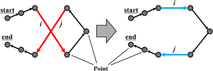
Fig. 11. 2-opt edge exchange for local path improvement.
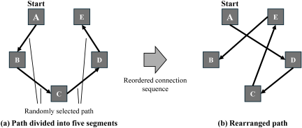
Fig. 12. Double-bridge perturbation for escaping local optima.
To address these issues, the proposed system incorporates an iterated local search (ILS) framework that employs a double-bridge operation as a perturbation mechanism. The ILS is a metaheuristic approach that begins by applying an LS to an initial solution to find a local optimum. Subsequently, a deliberate perturbation was applied to the local optimum, shifting the solution to a different region in the solution space, followed by another round of LSs. This process is repeated to enable a broader exploration beyond a single local optimum, thereby aiming to achieve higher-quality solutions overall 21. The double-bridge operation is a perturbation technique used to escape from a path that has converged through an LS and is characterized by its ability to introduce a larger structural change than local edge exchanges, such as the 2-opt method. In the proposed system, the starting point on the tool path is fixed; therefore, the segment containing the starting point is excluded from the operation, and the double-bridge operation is applied only to a portion of the path after the starting point. As shown in Fig. 12, several positions were randomly selected from the path, excluding the fixed starting point, and the path was divided into five subsegments (A, B, C, D, and E) (Fig. 12(a)). Subsequently, by rearranging the connection order of these subsegments, the reconstructed path is assigned a topology different from that of the original path (Fig. 12(b)). In this process, the order of points inside each subsegment is preserved, whereas only the connections between the subsegments are modified; thus, the global shape of the path changes significantly. Even when the starting point is fixed, this rearrangement enables the solution to jump away from the neighborhood of the current local optimum, making it easier for the subsequent 2-opt method to converge to a different local solution. Furthermore, the double-bridge operation has a low computational cost, making it well-suited for large-scale problems. By combining the double-bridge perturbation with the 2-opt LS, the system achieves both escape from local optima and search intensification.
In the proposed system, the initial path was first constructed using a greedy algorithm. The 2-opt method is then applied to this path to obtain a locally optimized solution. Subsequently, a double-bridge perturbation is introduced to generate a new solution that is significantly different from the current solution, followed by another round of LS using the 2-opt method. By iteratively repeating this process, the system can explore not only local optima but also globally superior solutions. Consequently, the point cloud can be rearranged into an effective sequence, enabling the generation of an optimized toolpath.
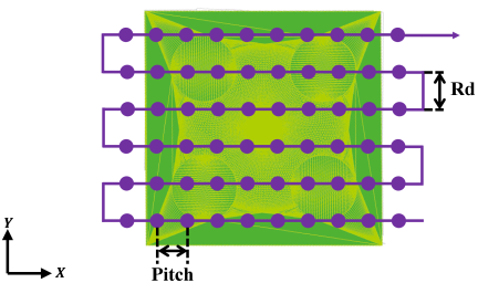
Fig. 13. Tool position on the \(XY\)-plane in scanning machining.
2.3. Toolpath Generation for Finishing Using Scanning Lines
For complex three-dimensional shapes composed of freeform surfaces, such as molds, high-precision finishing is required. In such machining processes, scanning line machining, in which the tool moves while following the surface of the product, is effective.
This method constructs linear toolpaths on the \(XY\)-plane and determines the contact points by performing interference checks between the discretely defined tool positions and the product surface, thereby calculating the tool position along the \(Z\)-axis 1. STL-format CAD models represent geometries using triangular mesh vertices and their corresponding normal vectors. These data can be used to identify the sloped and curved regions. By examining the \(Z\)-component of each triangle’s normal vector, it is possible to classify the triangle: a value of 1 or \(-1\) indicates a flat surface, a value of 0 indicates a vertical side, and any other value corresponds to an inclined or curved surface. As shown in Fig. 13, the tool positions were defined on the \(XY\)-plane based on the tool radius increment (\(\mathit{Rd}\)) and the resolution in the feed direction (pitch), and the corresponding \(Z\)-coordinates were calculated at each position.
The system calculates the \(Z\)-axis offset for each \(XY\) tool position. In a ball-end mill, the \(Z\)-offset is defined as the height at which the spherical tool tip contacts the triangle of the product surface. Specifically, the system geometrically computes the \(Z\)-coordinate corresponding to the highest valid contact between the spherical surface of the tool and triangle, considering the following three types of contact:
-
Contact between the sphere and a triangle face (Fig. 14(a));
-
Contact between the sphere and a triangle edge (Fig. 14(b));
-
Contact between the sphere and a triangle vertex (Fig. 14(c)).
The geometric relationship for face contact is shown in Fig. 15. In a three-dimensional space, given a unit normal vector \(\vec{n}\) and point \(A\) on the plane, the projection of point \(P\) onto the plane is denoted as \(H\). The following relationship holds.
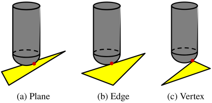
Fig. 14. Contact points between the ball-end mill and the triangle mesh for determining the tool position for scanning machining.
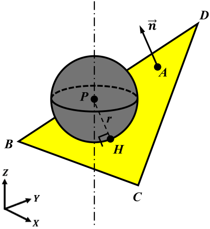
Fig. 15. Geometric relationship between a sphere and a plane.
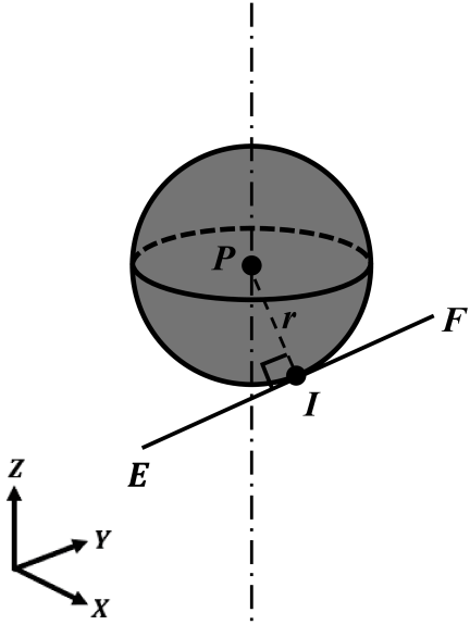
Fig. 16. Geometric relationship between a sphere and an edge.
Because the radius of the sphere is equal to the tool radius \(r\), the distance from the center point \(P\) to the contact point \(H\) must satisfy
Furthermore, the contact point must lie inside the target triangle, which requires that
The edge-contact relationship is shown in Fig. 16. Let \(I\) be the foot of the perpendicular drop from point \(P\) to edge segment \(\mathit{EF}\). The orthogonality condition was as follows:
Similarly, the radius condition is
To ensure that the contact lies within the edge segment, the following must hold.
Contact with vertices is considered a special case of edge contact. The system evaluates all triangles and their edges for each tool position determined in the \(XY\)-plane. By identifying point \(P\) that satisfies Eqs. \(\eqref{eq:eq2}\)–\(\eqref{eq:eq7}\) and has the maximum \(Z\)-value, the system determines the appropriate \(Z\)-axis tool height.
3. Case Study
Two case studies were conducted using mold CAD models to validate the effectiveness of the proposed system. In both case studies, the NC programs were generated using the developed system under the machining conditions listed in Table 1. The analyses were performed on a computer equipped with a CPU (Intel Core i7-12700H) and GPU (Nvidia GeForce RTX 3050 Ti laptop GPU). The workpiece material was an aluminum alloy (A5052), and machining was carried out using a three-axis machining center (ROBODRILL \(\alpha\)-D14MiB5, Fanuc Corporation). For comparison, the generated toolpaths were evaluated against a conventional approach, in which scanning-line machining was applied throughout roughing, semi-finishing, and finishing. Additionally, for the semi-finishing process of the remaining removal regions, the effects of the greedy algorithm, LS, and ILS were examined using simulated machining time.
To ensure a fair comparison, the same machining conditions were used for the proposed and conventional methods. These conditions were set conservatively to ensure stable verification during the actual machining. Therefore, the significance of the present comparison lies not in the absolute machining times themselves, but in demonstrating that the proposed system can automatically generate practical multiprocess toolpaths without manual adjustment and can reduce unnecessary tool motions under identical machining conditions.
3.1. Case Study 1
The first case study was conducted using the mold CAD model shown in Fig. 17. Fig. 17(a) shows an overview of the mold model, and Fig. 17(b) shows an enlarged view of the central region. The CAD model consisted of 460,946 triangular meshes. The total computation time required for toolpath generation was approximately 20 min, including 2, 3, and 15 min for roughing, semi-finishing, and finishing, respectively. This result indicates that the proposed system can generate multiprocess toolpaths for mold machining within a practical computation time.
Table 1. Machining conditions used in the case studies.

Machining was successfully performed by using the generated toolpaths. Casting was performed using a machined mold to obtain the desired cast shape. Figs. 17(c) and 17(d) show the machined results for A5052 and the casting results using tin as the casting material, respectively. The toolpaths generated by the proposed system for roughing, semi-finishing, and finishing are shown in Figs. 17(e), 17(f), and 17(g), respectively, whereas the toolpaths generated by the conventional scanning-line approach for roughing and semi-finishing are shown in Figs. 17(h) and 17(i), respectively.
Table 2 summarizes the simulated machining times for Case Study 1. In the proposed system, the roughing time was 53.52 min, and the finishing time was 449 min. Because toolpath optimization based on the greedy algorithm, LS, and ILS were applied to the semi-finishing process of the remaining removal regions, only the semi-finishing time differed among the methods. The semi-finishing time was 23.42 min when only the greedy algorithm was used, 22.41 min when LS was applied, and 22.28 min when ILS was further introduced. The total machining times were reduced to 525.94 min, 524.93 min, and 524.80 min, respectively. In contrast, the conventional scanning-line approach required 117.79 min for roughing, 90.11 min for semi-finishing, and 449 min for finishing, resulting in a total machining time of 656.90 min.
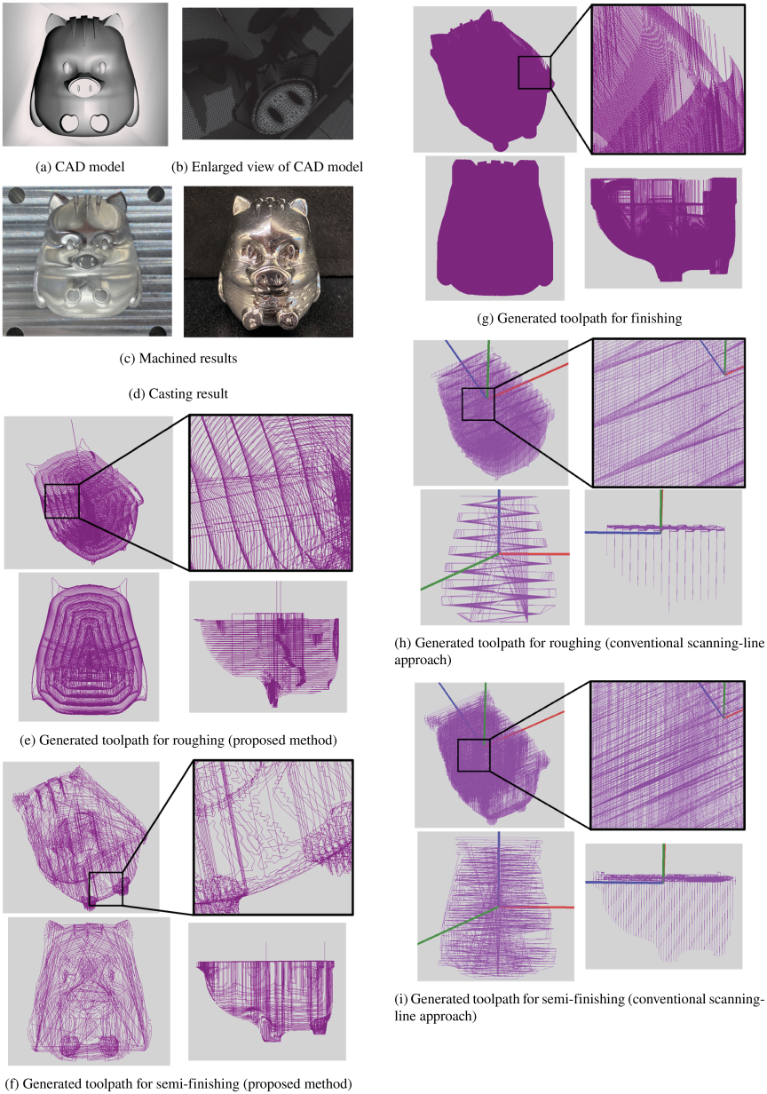
Fig. 17. CAD model and results of Case Study 1.
These results indicate that the proposed system substantially reduces the total machining time compared with the conventional scanning-line approach. In addition, a comparison of the three semi-finishing optimization methods showed that the introduction of the LS and ILS further shortened the semi-finishing time beyond the initial greedy path, although the improvement from the LS to ILS was limited in this case study.
In the conventional semi-finishing process adopted in this study, air-cut removal based on previous research 2 was applied. Therefore, the conventional method does not machine the entire region uniformly, regardless of the machined area. However, as shown in Fig. 17(i), unnecessary tool motion remained because the connectivity among the remaining separated removal regions was not optimized. By contrast, the semi-finishing toolpath generated by the proposed system, as shown in Fig. 17(f), is concentrated mainly around the remaining removal regions because the connection order of the corresponding toolpath segments was optimized using the greedy algorithm, LS, and ILS.
During roughing, the conventional scanning line toolpath shown in Fig. 17(h) involved more frequent entry and retraction motions than the contour-based roughing toolpath shown in Fig. 17(e), resulting in more plunging motions in the \(Z\)-direction. These factors contribute to an increase in the machining time in the conventional approach. Thus, the reduction in machining time in Case Study 1 was mainly achieved by decreasing the number of plunging motions in roughing and by reducing the number of inefficient tool motions in semi-finishing through connectivity optimization among the remaining removal regions.
3.2. Case Study 2
The second case study was conducted using another mold CAD model, as shown in Fig. 18. Fig. 18(a) shows an overview of the mold model, and Fig. 18(b) shows an enlarged view of the central region. The CAD model comprised 194,484 triangular meshes. The total computation time required for toolpath generation was approximately 15 min, including 2, 3, and 10 min for roughing, semi-finishing, and finishing, respectively. This result demonstrates that the proposed system can generate practical toolpaths for mold machining within a reasonable computational time.
Machining was successfully performed using the generated toolpaths. Casting was performed using a machined mold to obtain the intended cast shape. Figs. 18(c) and 18(d) show the machined results for A5052 and the casting results using tin as the casting material, respectively. The toolpaths generated by the proposed system for roughing, semi-finishing, and finishing are shown in Figs. 18(e), 18(f), and 18(g), respectively, whereas those generated by the conventional scanning-line approach for roughing and semi-finishing are shown in Figs. 18(h) and 18(i), respectively.
Table 2. Comparison of machining time [min] for Case Study 1.

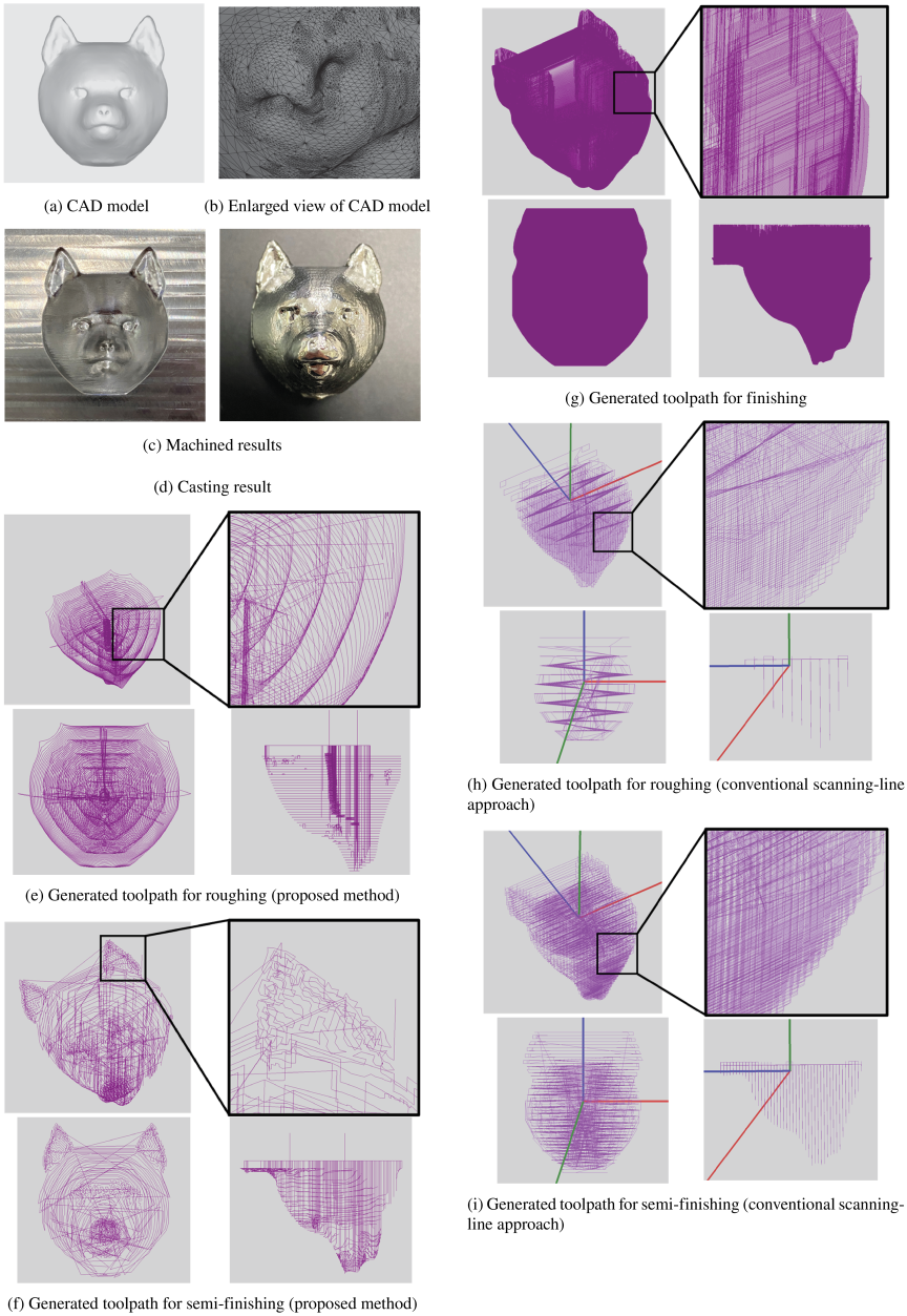
Fig. 18. CAD model and results of Case Study 2.
Table 3 summarizes the simulated machining times for Case Study 2. In the proposed system, the roughing time was 16.92 min, and the finishing time was 245 min. Because toolpath optimization based on the greedy algorithm, LS, and ILS were applied to the semi-finishing process of the remaining removal regions, only the semi-finishing time differed among the methods. The semi-finishing time was 11.59 min when only the greedy algorithm was used, 11.21 min when LS was applied, and 11.13 min when ILS was further introduced. As a result, the total machining time was reduced to 273.51 min, 273.13 min, and 273.05 min, respectively. In contrast, the conventional scanning-line approach required 25.58 min for roughing, 52.86 min for semi-finishing, and 245 min for finishing, resulting in a total machining time of 323.44 min.
These results indicate that the proposed system also reduced the total machining time in Case Study 2 compared with the conventional scanning-line approach. In addition, a comparison of the three semi-finishing optimization methods showed that the introduction of the LS and ILS further shortened the semi-finishing time beyond the initial greedy path, although the additional improvement from the LS to ILS was limited in this case study.
As in Case Study 1, the conventional semi-finishing process already includes air-cut removal, based on previous research 2. Nevertheless, as shown in Fig. 18(i), inefficient tool motion remained because the connectivity among the remaining separated removal regions was not optimized. By contrast, the semi-finishing toolpath generated by the proposed system, as shown in Fig. 18(f), is concentrated mainly around the remaining removal regions because the connection order of the corresponding toolpath segments is optimized using TSP-based algorithms.
Furthermore, the conventional roughing toolpath shown in Fig. 18(h) includes more frequent entry and retraction motions than the contour-based roughing toolpath shown in Fig. 18(e), which results in more plunging motions in the \(Z\)-direction and contributes to a longer machining time. Therefore, the reduction in machining time in Case Study 2 was mainly achieved by decreasing the plunging motions in roughing and by reducing the inefficient tool motions in semi-finishing through connectivity optimization among the remaining removal regions.
From these two case studies, it was confirmed that the proposed system can automatically generate practical multiprocess toolpaths for different mold geometries and reduce the machining time compared to the conventional scanning-line approach under identical machining conditions. In particular, the reduction in machining time was mainly achieved by decreasing the number of plunging motions in roughing and by reducing inefficient tool motions in semi-finishing through remaining-region-based path connectivity optimization, while maintaining machining feasibility and casting validity.
4. Conclusion
This paper presented an integrated framework for automatic multiprocess toolpath generation for die and mold machining using STL-format CAD models. The contribution of the proposed system does not lie in STL-based toolpath generation itself or in dexel-based extraction of remaining removal regions alone, both of which have been reported previously, but in the integration of process-specific toolpath generation and remaining-region-based path optimization across multiple machining stages. The main achievements of this study are summarized as follows.
-
A multiprocess toolpath-generation framework was developed to handle roughing, semi-finishing, and finishing in an integrated manner for die and mold machining based on STL-format CAD models.
-
In roughing and semi-finishing, the remaining removal regions were sequentially tracked across machining stages, and the resulting information was incorporated into the subsequent toolpath generation.
-
In semi-finishing, the connectivity among the toolpath segments corresponding to the remaining removal regions was optimized using the greedy algorithm, 2-opt method, and double-bridge operation, thereby reducing unnecessary tool motion.
-
The effectiveness of the proposed framework was validated through case studies and actual machining experiments, which confirmed that practical toolpaths could be generated automatically and that machining time could be reduced under identical machining conditions.
Future work will focus on the further automation of process planning, including the automatic selection of effective tool types and tool diameters according to the removal regions.
Table 3. Comparison of machining time [min] for Case Study 2.

Acknowledgments
This study was partially supported by the JSPS KAKENHI Grant Number JP25K01135.
- [1] I. Nishida, E. Yamada, and H. Nakatsuji, “Automated process planning system for machining injection molding dies using CAD models of product shapes in STL format,” Int. J. Automation Technol., Vol.17, No.6, pp. 619-626, 2023. https://doi.org/10.20965/ijat.2023.p0619
- [2] K. Matsukawa, H. Nakatsuji, and I. Nishida, “Automated tool-path generation for complex shapes applicable to 5-axis indexing machining using STL-format CAD models,” Int. J. Automation Technol., Vol.19, No.5, pp. 698-711, 2025. https://doi.org/10.20965/ijat.2025.p0698
- [3] E. Morinaga, M. Yamada, H. Wakamatsu, and E. Arai, “Flexible process planning method for milling,” Int. J. Automation Technol., Vol.5, No.5, pp. 700-707, 2011. https://doi.org/10.20965/ijat.2011.p0700
- [4] K. Dwijayanti and H. Aoyama, “Basic study on process planning for turning-milling center based on machining feature recognition,” J. Adv. Mech. Des. Syst. Manuf., Vol.8, No.4, Article No.14-00096, 2014. https://doi.org/10.1299/jamdsm.2014jamdsm0058
- [5] H. Sakurai, “Volume decomposition and feature recognition: Part 1—polyhedral objects,” Comput.-Aided Des., Vol.27, No.11, pp. 833-843, 1995. https://doi.org/10.1016/0010-4485(95)00007-0
- [6] H. Sakurai and P. Dave, “Volume decomposition and feature recognition: Part II—curved objects,” Comput.-Aided Des., Vol.28, Nos.6-7, pp. 519-537, 1996. https://doi.org/10.1016/0010-4485(95)00067-4
- [7] B. K. Choi and K. Ko, “C-space based CAPP algorithm for freeform die-cavity machining,” Comput.-Aided Des., Vol.35, No.2, pp. 179-189, 2003. https://doi.org/10.1016/S0010-4485(02)00051-9
- [8] W.-R. Jong, P.-J. Lai, Y.-W. Chen, and Y.-H. Ting, “Automatic process planning of mold components with integration of feature recognition and group technology,” Int. J. Adv. Manuf. Technol., Vol.78, Nos.5-8, pp. 807-824, 2015. https://doi.org/10.1007/s00170-014-6627-4
- [9] C.-S. Jun, D.-S. Kim, and S. Park, “A new curve-based approach to polyhedral machining,” Comput.-Aided Des., Vol.34, No.5, pp. 379-389, 2002. https://doi.org/10.1016/S0010-4485(01)00110-5
- [10] K. Nakamoto, K. Shirase, H. Wakamatsu, A. Tsumaya, and E. Arai, “Automatic production planning system to achieve flexible direct machining,” JSME Int. J. C Mech. Syst. Mach. Elem. Manuf., Vol.47, No.1, pp. 136-143, 2004. https://doi.org/10.1299/jsmec.47.136
- [11] A. Ueno and K. Nakamoto, “Proposal of machining features for CAPP system for multi-tasking machine tools,” Trans. JSME, Vol.81, No.825, Article No.15-00108, 2015 (in Japanese). https://doi.org/10.1299/transjsme.15-00108
- [12] E. Morinaga, T. Hara, H. Joko, H. Wakamatsu, and E. Arai, “Improvement of computational efficiency in flexible computer-aided process planning,” Int. J. Automation Technol., Vol.8, No.3, pp. 396-405, 2014. https://doi.org/10.20965/ijat.2014.p0396
- [13] I. Nishida, H. Nakatsuji, and K. Shirase, “Automated tool path generation for roughing using flat drill,” Int. J. Automation Technol., Vol.14, No.6, pp. 1036-1044, 2020. https://doi.org/10.20965/ijat.2020.p1036
- [14] I. Nishida and K. Shirase, “Automated process planning system for end-milling operation by CAD model in STL format,” Int. J. Automation Technol., Vol.15, No.2, pp. 149-157, 2021. https://doi.org/10.20965/ijat.2021.p0149
- [15] H. Rushmeier, G. Greiner, and K. Hormann, “Efficient clipping of arbitrary polygons,” ACM Trans. Graph., Vol.17, No.2, pp. 71-83, 1998. https://doi.org/10.1145/274363.274364
- [16] E. L. Foster, K. Hormann, and R. T. Popa, “Clipping simple polygons with degenerate intersections,” Comput. Graph.: X, Vol.2, Article No.100007, 2019. https://doi.org/10.1016/j.cagx.2019.100007
- [17] M. Inui, T. Sakurai, and N. Umezu, “Data conversion technology between triple dexel model and polygonal model,” J. Jpn. Soc. Precis. Eng., Vol.76, No.2, pp. 226-231, 2010 (in Japanese). https://doi.org/10.2493/jjspe.76.226
- [18] M. Inui and N. Umezu, “Contour-type cutter path computation using ultra-high-resolution dexel model,” Comput.-Aided Des. Appl., Vol.17, No.3, pp. 621-638, 2020. https://doi.org/10.14733/cadaps.2020.621-638
- [19] D. J. Rosenkrantz, R. E. Stearns, and P. M. Lewis, “Approximate algorithms for the traveling salesperson problem,” 15th Annu. Symp. Switch. Autom. Theory, pp. 33-42, 1974. https://doi.org/10.1109/SWAT.1974.4
- [20] G. A. Croes, “A method for solving traveling-salesman problems,” Oper. Res., Vol.6, No.6, pp. 791-812, 1958. https://doi.org/10.1287/opre.6.6.791
- [21] S. Lin and B. W. Kernighan, “An effective heuristic algorithm for the traveling-salesman problem,” Oper. Res., Vol.21, No.2, pp. 498-516, 1973. https://doi.org/10.1287/opre.21.2.498
This article is published under a Creative Commons Attribution-NoDerivatives 4.0 Internationa License.