Research Paper:
Automated Process Planning for Machining Organic Shapes Using Eccentric-Axis Turning
Kentaro Matsukawa, Hidenori Nakatsuji, and Isamu Nishida†

Graduate School of Engineering, Kobe University
1-1 Rokkodai-cho, Nada-ku, Kobe, Hyogo 657-8501, Japan
†Corresponding author

With the shift toward high-mix, low-volume production, the proportion of process planning within the overall manufacturing lead time has increased. This issue is particularly critical in the medical field, where custom-made production of organically shaped components with complex curved surfaces is required, while the number of experienced workers responsible for process planning is decreasing. Typically, machining of models with complex curved surfaces is performed by milling processes, including 5-axis indexing machining and 5-axis simultaneous machining. However, cycle time can be reduced by incorporating additional machining processes, such as turning, alongside milling. Recently, the development of multitasking machine tools equipped with eccentric-axis turning functions has enabled greater machining flexibility and the potential for reduced machining time. Nevertheless, methods for tool path generation and numerical control (NC) program generation that effectively utilize eccentric-axis turning have not yet been sufficiently established. Therefore, in this study, an automated process planning and tool path generation method was proposed that applies eccentric-axis turning to the roughing stage for organically shaped components. In the proposed method, workpiece dimensions and product placement are determined based on shape analysis of a three-dimensional computer-aided design model in Standard Triangulated Language format, and an intermediate shape suitable for eccentric-axis turning is automatically extracted. Furthermore, for regions where material removal by turning is difficult, scanning machining that considers air cuts is applied, and tool paths for each process are generated. To verify the effectiveness of the proposed method, analytical evaluation and actual machining experiments were conducted using organically shaped components. The results confirm that the proposed method appropriately performs shape analysis and NC program generation, and that roughing using eccentric-axis turning is effective in reducing machining time for organically shaped components.
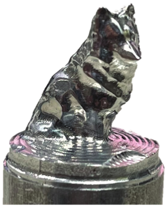
Result of machined product shape in Case study 2
1. Introduction
In recent years, with the shift toward high-mix, low-volume production in manufacturing industries, the necessity of process planning for individual products has increased 1,2,3. At the same time, the retirement of experienced workers and the decline in the working population have led to constraints on the human resources responsible for process planning, making the improvement of efficiency and automation of process planning an important issue. To achieve efficient and automated process planning, it is essential to automate a series of procedures, including process planning and tool-path determination based on product geometry.
Numerous studies on automatic tool-path generation have been reported, and review papers summarizing these methods have been published 4. In addition, various individual approaches have been proposed, such as machining feature recognition methods based on target geometry 5,6,7,8 and methods that define machining regions based on removal volumes 9,10,11,12,13,14. Although these studies have demonstrated effective approaches for achieving high-precision machining and automatic determination of tool orientations, computational cost and machining time often increase when applied to complex, organically shaped products, such as dental implants, artificial bones, and products designed through generative design 15,16. In particular, when these methods are directly applied to roughing processes, their practical application in actual machining often becomes difficult from the viewpoints of computational cost and machining time.
Many studies have also been conducted on process planning and numerical control (NC) program generation for multitasking machine tools 17,18,19. A multitasking machine tool integrates the functions of a 5-axis machining center and an NC lathe, enabling highly efficient machining by consolidating multiple processes and using multi-axis spindles 20. However, as machining freedom increases, the design of tool paths and machining conditions becomes more complex. For complex geometries, the difficulty of generating practical tool paths suitable for actual machining has been highlighted.
Studies have also reported tool-path generation for hybrid machining that combines conventional turning for roughing with milling for semi-finishing and finishing processes, targeting organically shaped components with complex curved surfaces 21. These studies reduced overall machining time by applying high-efficiency turning in the roughing stage. However, automated process planning in these studies is limited to conventional turning, where the workpiece center serves as the rotation axis. As a result, they did not address the problem of automatically determining an intermediate shape and the corresponding NC programs when the roughing operation involves eccentric-axis rotation.
Related technologies, such as noncircular turning and synchronized turning, have also been investigated for generating non-axisymmetric geometries by synchronizing tool motion with spindle rotation 22,23,24. Many of these studies have focused on machining control, servo control, and tool motion required to generate a prescribed non-axisymmetric geometry. Typically, the target geometry is provided in advance, and the main challenge is realizing that geometry through synchronized tool motion. In contrast, the present study addresses a different problem: how to automatically derive a machinable intermediate shape for eccentric axis turning from a Standard Triangulated Language (STL)-format computer-aided design (CAD) model of an organically shaped component and how to connect this roughing process to the subsequent milling process.
Therefore, the focus of this study was on the roughing process of organically shaped components, and a tool-path generation method was proposed that actively uses eccentric-axis turning to address the issue of low rotational symmetry with respect to the workpiece center, which reduces material removal efficiency in conventional turning. In the proposed method, geometric shape analysis is performed using an STL-format CAD model as input. An intermediate shape suitable for eccentric-axis turning is automatically extracted, and NC programs are generated for both the eccentric-axis turning roughing stage and the subsequent milling stage. Furthermore, the rough-machined intermediate shape is represented using a dexel model, enabling automatic detection and removal of air cut regions in the subsequent milling process. Thus, the novelty of this study lies not in proposing a new principle of synchronized or noncircular turning but in the automated linkage of STL-based shape analysis, eccentric-axis turning roughing, dexel-based intermediate shape representation, and milling tool-path generation for organically shaped components.
The remainder of this paper is organized as follows: Section 2 provides an overview of the NC program generation method for eccentric axis turning and system configuration. Section 3 explains the NC program generation method for milling in the semi-finishing and finishing stages. Section 4 presents the machining experiments conducted to verify the effectiveness of the proposed method and discusses the results.
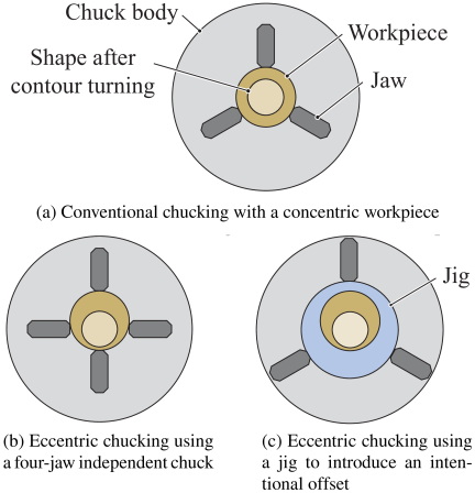
Fig. 1. Workpiece chucking methods for eccentric-axis turning on a conventional lathe.
2. Automated Process Planning for the Roughing Stage in Eccentric-Axis Turning
2.1. Overview of Eccentric-Axis Turning
In conventional turning, the center of the workpiece serves as the rotation axis; so the machinable geometry is limited to concentric circular shapes about that axis. In contrast, eccentric-axis turning is a machining method that does not follow this principle.
On a conventional engine lathe, eccentric-axis turning can be achieved by intentionally offsetting the clamping position of the workpiece, as shown in Fig. 1, using a four-jaw independent chuck or fixture fabricated by milling. This approach has conventionally been used to manufacture components with eccentric geometries, such as cams and eccentric shafts.
However, recent CNC machine tools enable high-precision control of tool position and spindle rotation. As illustrated in Fig. 2, eccentric-axis turning with arbitrary eccentricity and phase can be performed without changing the chucking position of the workpiece by synchronizing the tool motion with the workpiece rotation. With such control, cutting that would otherwise be intermittent on a conventional engine lathe can, in some cases, be performed as continuous cutting, thereby reducing the load on the cutting tool.
However, in eccentric-axis turning, the tool post must be driven at high speed in synchronization with spindle rotation. Therefore, it is often necessary to limit the spindle rotational speed compared to conventional turning operations, especially in large machine tools.
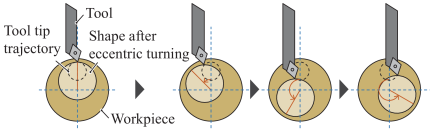
Fig. 2. Concept of tool-synchronized motion in eccentric-axis turning.
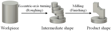
Fig. 3. Machining process combining eccentric-axis turning and milling.
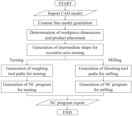
Fig. 4. Overall workflow of the proposed automated NC program generation system.
2.2. Overview of the Proposed Algorithm
In this paper a system is proposed that automatically generates tool paths by effectively combining turning, which provides high material removal efficiency, and milling, which offers high geometric flexibility. The objective is to achieve efficient machining of organically shaped components. In particular, the proposed method actively uses eccentric axis turning during the roughing stage to reduce roughing time for organically shaped geometries.
As shown in Fig. 3, the proposed process first machines a cylindrical bar stock into an intermediate shape using eccentric axis turning. Subsequently, semi-finishing and finishing operations are performed using milling. Through this process configuration, the roughing time for organically shaped components is reduced.
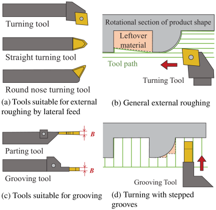
Fig. 5. Classification of turning tools and corresponding machining methods.
Figure 4 illustrates the overall processing flow of the proposed system. First, an STL-format CAD model representing the product geometry is provided as input and converted into a contour line model, as described later. Based on this contour line model, the required workpiece dimensions and the center positions of the product within the workpiece are determined.
Next, for the lathe roughing stage, cylindrical machining regions are extracted by considering the tool information and machining conditions. Subsequently, for the milling stage, the scanning machining tool paths considering the air cut are calculated. Finally, an NC program is developed based on the results of these analyses.
2.3. Tool Path Generation in Eccentric-Axis Turning
2.3.1. Cutting Tools Used in This Study
In this study, the cutting tools used for turning were classified into two types based on the machining method.
The first type consists of single-point turning tools, such as straight-turning tools and pointed tools, as shown in Fig. 5(a). These tools perform cutting primarily by feeding in the radial direction. They are suitable for contour roughing operations, as illustrated in Fig. 5(b), and enable high material removal efficiency for relatively smooth geometries or large-scale products because tool interference is less likely to occur. However, when the geometry has significant concavity and convexity, or when the tool size is relatively large compared to the geometric scale, the available approach directions are restricted due to tool interference. Consequently, the effectiveness of reducing roughing time tends to be limited.
The second type includes tools, such as parting and grooving tools, as shown in Fig. 5(c), which perform cutting by feeding in the axial direction. In this case, the workpiece material is removed incrementally based on the tool width. The cutting edge width \(B\) is a geometric parameter that defines the width of the region removed in a single cutting pass. As illustrated in Fig. 5(d), machining with this type of tool can be interpreted as turning, where the product geometry is represented as a set of cylindrical volumes with constant width. However, appropriate selection of tool width according to the product geometry is required, and when the target removal region is large, the machining efficiency is generally lower than that of tools that primarily use radial feed.
Because the products targeted in this study, such as medical device components, were relatively small and had organically shaped geometries, the latter type of tool is used for turning operations. The tool width is specified by the system operator and assumed to be within the range of typical tool specifications.
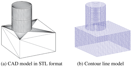
Fig. 6. Conversion of computer-aided design (CAD) model in Standard Triangulated Language (STL) format to a contour line model.
2.3.2. Contour Line Model for Extracting the Intermediate Shape
In this study, an STL-format CAD model in which the surface of a three-dimensional geometry is represented by triangular meshes was used as the input for geometric analysis. In general, meshes representing planar regions tend to be coarse, whereas those representing curved surfaces tend to be finer. Therefore, direct analysis based solely on a triangular mesh may result in uneven geometric resolution.
To address this issue, a contour line model converted from an STL-format CAD model was used for subsequent analysis. As shown in Fig. 6, the contour line model represents the product geometry by slicing the model with planes perpendicular to an arbitrary orthogonal axis and superimposing the outer contour lines obtained from each cross section. By stacking these contour lines, the three-dimensional geometry can be represented in a form suitable for geometric processing and intermediate shape extraction.
First, the CAD model is sliced at fine intervals using planes perpendicular to the turning rotation axis, as shown in Fig. 7(a). For each cross section, the intersection points between the plane and the edges of the triangular meshes are calculated. By connecting these intersection points, the intersection lines between the triangular meshes and the slicing plane are obtained. Because adjacent triangular meshes share common edges, they also share common intersection points; therefore, connecting these points generates a contour line for each cross section, as illustrated in Fig. 7(b).
When the distance between adjacent points exceeds a specified spatial resolution, additional points are inserted by linear interpolation, as shown in Fig. 7(c). Finally, by stacking all generated cross sections sequentially, the original CAD model is converted into a discrete point cloud suitable for subsequent geometric analysis.
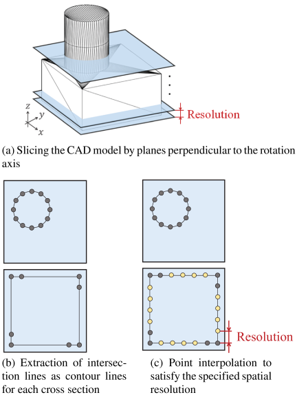
Fig. 7. Process to obtain contour line model and discrete point clouds from CAD model in STL format.
2.3.3. Determination of Workpiece Dimensions and Product Position
This section describes the method for automatically determining the minimum required dimensions of a workpiece for machining. It is assumed that the operator prepares a bar stock whose dimensions exceed the calculated minimum values. Because the product must be completely contained within the workpiece, its position inside the workpiece is determined simultaneously along with its dimensions.
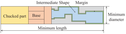
Fig. 8. Cross-sectional view of the workpiece showing the minimum required dimensions.
Because the roughing stage is performed by turning, the workpiece is assumed to be a cylindrical bar. As illustrated in Fig. 8, the minimum required length of the workpiece is determined by considering not only the product length, but also the machining allowance, portion removed during cutoff, the chuck gripping length required for turning, and the base length required when milling is performed in a separate process.
Alternatively, the position of the product within the workpiece is preferably determined to minimize the volume of material to be removed. To achieve this, a minimum-diameter cylinder that completely encloses the product geometry is calculated, and the product is positioned so that the central axis of this cylinder coincides with the turning rotation axis. The minimum required workpiece diameter is then defined as the diameter of the enclosing cylinder plus an additional machining allowance.
The algorithm for calculating the minimum diameter of the cylinder that encloses the product geometry based on the contour line model is described below. In this study, the turning rotation axis is defined as the \(Z\)-axis in the Cartesian coordinate system.
The contour line model consists of point clouds representing the outer contour of each cross section obtained by slicing the CAD model with planes perpendicular to the turning rotation axis. In this analysis, each cross section is evaluated as a planar shape orthogonal to the rotation axis; therefore, the contour line model is treated as a set of point clouds on the \(XY\)-plane.
To reduce computational time, points whose differences in both \(x\)- and \(y\)- coordinates are below a predefined threshold are removed from the point cloud. The convex hull of the remaining point set is then constructed using the Graham scan algorithm.
Next, Welzl’s algorithm is applied to compute the minimum enclosing circle of the point set. This procedure yields the diameter and center position of the minimum circle that encloses the product geometry.
The problem of determining the smallest circle that encloses a set of points on a plane is known as the minimum enclosing circle problem. Several solution methods have been proposed for this problem. In this study, the algorithm proposed by Welzl was adopted.
Welzl’s algorithm proceeds as follows. First, an arbitrary point \(p_1\) is removed from the point set \(P\), and the minimum enclosing circle of the remaining set \(P'\) is computed. If \(p_1\) lies inside the resulting circle, then this circle is the minimum enclosing circle of the original set \(P\) (Fig. 9(a)). Conversely, if \(p_1\) lies outside the circle, the minimum enclosing circle of \(P\) must include \(p_1\) on its boundary (Fig. 9(b)).
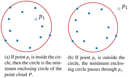
Fig. 9. Minimum enclosing circle of \(P'\), where \(P'\) is obtained by removing point \(p_1\) from \(P\).
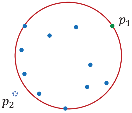
Fig. 10. Minimum enclosing circle of the point cloud \(P''\) passing through the points of point cloud \(R\).
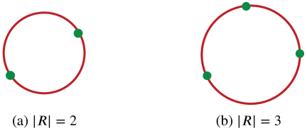
Fig. 11. Minimum enclosing circle when point cloud \(P^{(n)}\) is empty.
In the latter case, let \(R\) denote the set of points that must lie on the boundary of the circle, and add \(p_1\) to \(R\). Then, another point \(p_2\) is removed from \(P'\), and the minimum enclosing circle of the remaining set \(P''\), which also contains all points in \(R\) on its boundary, is computed (Fig. 10). By repeating this procedure recursively and checking whether each removed point lies inside or outside the current circle, the minimum enclosing circle is ultimately obtained.
As points are removed individually, all points are eventually eliminated, and set \(R\), which contains the points that must lie on the boundary of the circle, includes between zero and three points. The provisional minimum enclosing circle at this stage is determined by the number of points in \(R\), as described below.
If \(R\) contains zero or one point, the minimum enclosing circle is trivially defined as a circle with zero radius. If \(R\) contains two points, the minimum enclosing circle is defined as the circle whose diameter is the line segment connecting these two points (Fig. 11(a)). If \(R\) contains three points, the minimum enclosing circle is given by the circumcircle of the triangle formed by these three points, with its center at the circumcenter (Fig. 11(b)).
For two points \((x_1, y_1)\) and \((x_2,y_2)\), the center \((x_C,y_C)\) and radius \(r_C\) of the circle with the line segment between them as its diameter are calculated from the midpoint and the distance between the two points as follows:
However, for the three points \((x_1,y_1)\), \((x_2,y_2)\), and \((x_3,y_3)\), the center \((x_C,y_C)\) and radius \(r_C\) of the circumcircle are determined from the properties of the circumcenter. Because all three points lie on the circumference, the following relations hold:
By solving Eq. \(\eqref{eq:2}\), the center and radius of the circumcircle can be obtained as follows. For simplicity, auxiliary quantities \(A\), \(B\), and \(D\) are introduced as defined below.
Accordingly, the center coordinates and radius of the circumcircle are given by the following equations:
Welzl’s algorithm searches for points that lie on the boundary of a minimum enclosing circle. However, the number of points in the contour line model used as the input is extremely large, and the direct application of the algorithm increases computational time. Therefore, in this study, points unnecessary for the analysis were removed in advance to reduce computational cost.
Because Welzl’s algorithm identifies points that lie on the boundary of the minimum enclosing circle, only points that can potentially appear on the circumference of the minimum enclosing circle are required for computation.
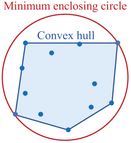
Fig. 12. Calculation of the minimum enclosing circle when the convex hull encompasses all points, and the minimum enclosing circle encompasses the convex hull.
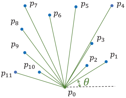
Fig. 13. The point cloud is sorted by angle from the reference point.
As shown in Fig. 12, a convex hull is the smallest convex set enclosing a given point cloud, and the minimum enclosing circle must enclose this convex hull. In other words, if a point lies inside the convex hull, it cannot appear on the circumference of the minimum enclosing circle outside the convex hull.
Accordingly, it is sufficient to use only the vertices of the convex hull to compute the minimum enclosing circle, and points located inside the convex hull can be removed as unnecessary for analysis.
The Graham scan algorithm is an efficient method for computing the convex hull of a point set. In this algorithm, a reference point is first selected. The point with the smallest \(y\)-coordinate is chosen as the reference point; if multiple points share the same minimum \(y\)-coordinate, the point with the smallest \(x\)-coordinate is selected. Because this reference point is at the lowest position in the point cloud, it is guaranteed to be a vertex of the convex hull.
Next, the remaining points are sorted in counterclockwise order based on the polar angle measured from the reference point. A sequence of points is then constructed with the reference point placed at the beginning of the list, as illustrated in Fig. 13.
Subsequently, points from the second element onward in the sorted sequence are processed sequentially to determine whether each point is a vertex of the convex hull.
Let the point under consideration be \(p_k(x_k,y_k)\), the preceding point be \(p_{k-1}(x_{k-1},y_{k-1})\), and the succeeding point be \(p_{k+1}(x_{k+1},y_{k+1})\). The determination is performed based on the relationship between the vectors \(\overrightarrow{p_{k-1}p_k}\) and \(\overrightarrow{p_{k-1}p_{k+1}}\).
Because the points are arranged in counterclockwise order with respect to the reference point, point \(p_k\) forms a convex vertex with respect to its adjacent points \(p_{k-1}\) and \(p_{k+1}\) if the vector \(\overrightarrow{p_{k-1}p_{k+1}}\) lies counterclockwise relative to \(\overrightarrow{p_{k-1}p_k}\).
This condition is equivalent to the positive \(z\)-component of the cross-product.
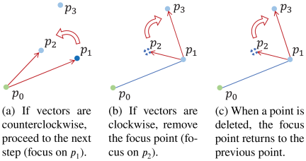
Fig. 14. Graham scan algorithm.
If \(D>0\), point \(p_k\) is a vertex of the convex hull, and the algorithm evaluates the next point (Fig. 14(a)).
If \(D\le 0\), the point \(p_k\) is not a vertex of the convex hull and must be removed from the sequence (Fig. 14(b)). In this case, because the succeeding point relative to \(p_{k-1}\) changes after deleting \(p_k\), the algorithm re-evaluates using \(p_{k-1}\) as the current focus point (Fig. 14(c)).
By repeating this procedure until the end of the sequence is reached, only the vertices that constitute the convex hull remain in the list. The point following the last point in the sequence is treated as the reference point.
2.3.4. Extraction of the Intermediate Shape for Eccentric-Axis Turning
When eccentric axis turning is performed using a grooving or parting tool, the intermediate shape obtained after roughing consists of multiple cylindrical volumes that enclose the product geometry. Therefore, to generate tool paths for turning roughing, it is necessary to obtain a set of cylinders that enclose the product geometry as the target intermediate shape. In this study, the previously described minimum enclosing circle algorithm is applied to each region corresponding to an individual cylinder to determine the center position and diameter of each cylindrical cross section constituting the intermediate shape. The height of each region in the \(Z\)-direction is defined based on the cutting edge width of the grooving tool.
However, the minimum enclosing circle obtained using Welzl’s algorithm may not always be completely contained within the workpiece. When the point cloud is distributed near the outer boundary of the stock, as shown in Fig. 15(a), the center of the circle may be located outside the workpiece, resulting in a cylinder that extends beyond the material. Machining based on such a cylindrical geometry leads to intermittent cutting because the tool repeatedly enters and exits the material region, increasing the cutting impact and reducing tool life.
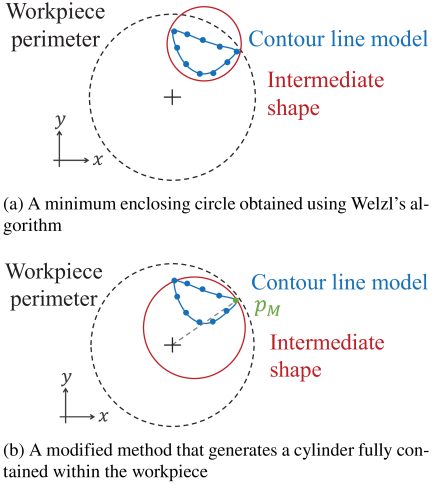
Fig. 15. Generation of cylindrical intermediate shapes.
To avoid this problem, when the minimum enclosing circle computed using Welzl’s algorithm is not fully contained within the workpiece, the cylindrical geometry is recalculated using an alternative method. As illustrated in Fig. 15(b), a circle is constructed so that it passes through point \(p_M(x_M,y_M)\), which is the farthest point from the rotation axis, and its center lies on the line segment connecting the rotation axis and \(p_M\). Among the circles satisfying these geometric constraints, the circle with the minimum diameter is selected. Because this circle is guaranteed to be fully contained within the workpiece, machining can be performed without causing intermittent cutting.
However, because the circle obtained by this method is not the minimum enclosing circle, the circle derived from Welzl’s algorithm is preferable from the viewpoint of tool travel distance and machining efficiency, provided that intermittent cutting does not occur during machining.
The detailed procedure of the proposed method is as follows. First, a circle with its center coinciding with the rotation axis is generated as the initial circle. Next, while maintaining the geometric constraints that the circle passes through point \(p_M(x_M,y_M)\), which is the farthest point from the rotation axis, and that the center of the circle lies on the straight line connecting the rotation axis and \(p_M\), the diameter of the circle is gradually reduced.
Let the diameter of the circle be \(r\), and the center coordinates be \((x_C,y_C)\). Under these constraints, the center of the circle is expressed as
The diameter is iteratively reduced by a predefined decrement \(\Delta r\). After each reduction step, it is verified whether all the points in the point cloud are contained within the circle. A point \(p(x_p,y_p)\) is considered to be inside the circle if the following condition is satisfied:
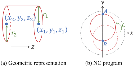
Fig. 16. Conversion from cylindrical geometric representation to NC program.
The reduction process is repeated until a point not contained within the circle appears for the first time, at which point further reduction is terminated. To compensate for the discretization introduced by the decrement \(\Delta r\), the diameter is then slightly increased by a small adjustment parameter \(\varepsilon\). Once it is confirmed that all points are again contained within the circle, the final enclosing circle is determined.
2.3.5. NC Program Generation
Each cylindrical region is stored as a list of geometric information that includes the center coordinates and radii of the circles located at both ends of the region, together with the assigned machining method. The machining method is associated with the cutting tool used. For example, in grooving operations, the width of the cylindrical region (i.e., the difference between the \(z\)-coordinates of the two end-circle centers) is set to match the tool width. Therefore, the stored geometric information can be readily converted into tool paths.
In this study, the NC program required for eccentric axis turning was generated directly using these geometric descriptors. As an example, consider the case where the rotation angle \(C\) at which the cylindrical geometry reaches the highest position. The \(Y\)-direction diameter values \(A\) and \(B\) at the upper and lower ends of the machining endpoint are required as NC program parameters, as illustrated in Fig. 16(a). As shown in Fig. 16(b), an NC program for grooving is generated from the geometric information list that stores the end-circle center coordinates \((x_1,y_1,z_1)\) and \((x_2,y_2,z_2)\) and radii \(r_1\) and \(r_2\).
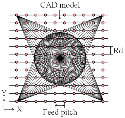
Fig. 17. Tool positions on the \(XY\)-plane in scanning machining.
The feed rate \(F\) is determined based on the workpiece material and cutting conditions. The spindle speed \(S\) is set within an appropriate range for eccentric-axis turning, taking into account the machine dynamics and synchronization requirements. After the grooving operation is completed, a tool-retraction command is appended, thereby generating an NC program corresponding to one cylindrical region.
3. Automated NC Program Generation for Milling Considering Air Cut Regions
3.1. Tool Path Generation in Milling
In this study, milling was used as the semi-finishing and finishing processes to transform the intermediate shape, represented as a set of cylindrical volumes, into the final product geometry. However, organically shaped components often include freeform surfaces, making it difficult to apply conventional contour-based machining derived from feature-based analysis 5,6,7,8,9,10,11,12.
Therefore, scanning machining was used in this study. Scanning machining is a method in which the tool moves in a zigzag or unidirectional pattern on the \(XY\)-plane while applying a \(Z\)-axis offset corresponding to the product geometry.
The tool path for scanning machining can be computed by considering only the \(Z\)-direction offset determined from the interference between the tool and product geometries at each tool position on the \(XY\)-plane 25.
Accordingly, the tool positions on the \(XY\)-plane are first determined based on the radial depth of cut \(R_d\) and the feed-direction resolution (pitch), as illustrated in Fig. 17.
Next, the \(Z\)-direction offset is calculated for each tool position determined on the \(XY\)-plane. In this paper, the geometric analysis for a ball-end mill is described.
For a ball-end mill, the \(Z\)-direction offset can be defined as the position at which the spherical tip of the tool meets a triangular mesh representing the product geometry. For each triangular mesh, the center position of the sphere is geometrically calculated for the following contact conditions: contact between the sphere and face (Fig. 18(a)), contact between the sphere and edge (Fig. 18(b)), and contact between the sphere and vertex (Fig. 18(c)).
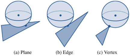
Fig. 18. Positional relationship between tool and triangular mesh contacts.
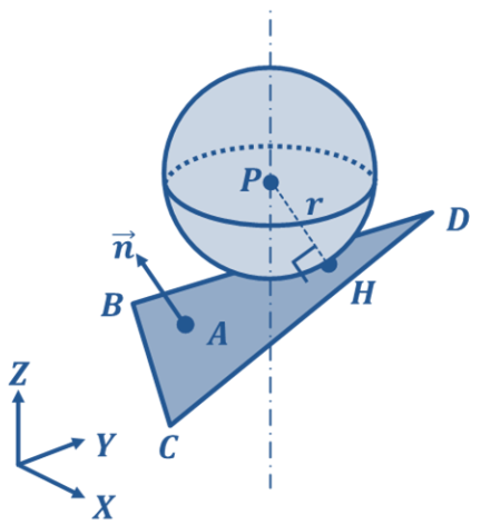
Fig. 19. Geometric relationship between sphere and plane.
Among these candidates, the sphere center position that yields the maximum \(Z\)-value is selected as the valid tool offset at the given \(XY\) position.
The geometric relationship between the plane and sphere in contact is shown in Fig. 19. In three-dimensional space, consider a plane represented by a unit normal vector \(\overrightarrow{n}\) and point \(A\) lying on the plane. Let \(H\) be the projection of point \(P\) onto the plane. The following relationship holds.
As the sphere centered at \(P\) has a radius equal to the tool radius \(r\), the following condition must be satisfied:
Furthermore, for the contact point to lie within the target triangular mesh, the following condition must be satisfied.
The geometric relationship between an edge and sphere in contact is shown in Fig. 20. In three-dimensional space, let \(I\) be the foot perpendicular from point \(P\) to line segment \(\textit{EF}\). The following orthogonality condition holds:
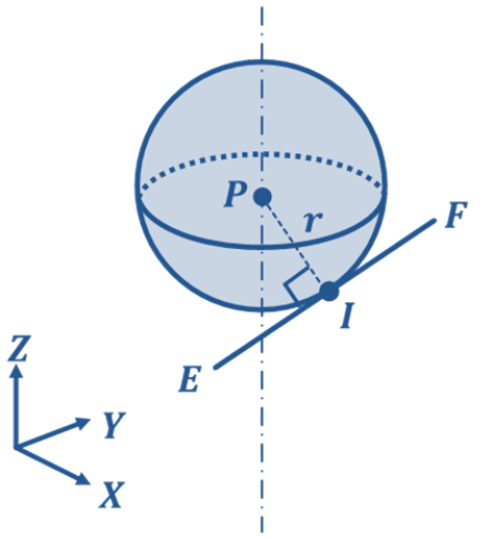
Fig. 20. Geometric positional relationship between spheres and edges.
Because the sphere is centered at \(P\) and has radius \(r\), the following condition must also be satisfied:
In addition, for the contact point to lie within line segment \(\textit{EF}\), the following condition must hold:
The vertex–sphere contact condition is included in the edge–sphere contact case.
For each tool position determined on the \(XY\)-plane, the tool center position is calculated by evaluating all triangular meshes and their edges and determining the point \(P\) that satisfies Eqs. \(\eqref{eq:11}\)–\(\eqref{eq:16}\) and yields the maximum \(Z\)-coordinate.
3.2. Air Cut Detection and Tool Path Modification Using the Dexel Model
The tool paths for scanning machining in the semi-finishing stage calculated in the previous section are generated uniformly based on the final product geometry without considering the intermediate shape obtained after roughing. As a result, tool motions are included even in regions where material has already been removed during roughing, leading to a large number of air cuts that do not involve material removal.
To address this issue, a method is proposed for automatically detecting air cut regions and modifying tool paths by constructing a machining simulation based on a dexel model that represents the intermediate shape obtained through eccentric-axis turning. As shown in Fig. 21(a), the dexel model is a geometric representation in which the workpiece is discretized by numerous parallel lines in the \(Z\)-direction and is widely used for the geometric representation of machining regions [26–28].
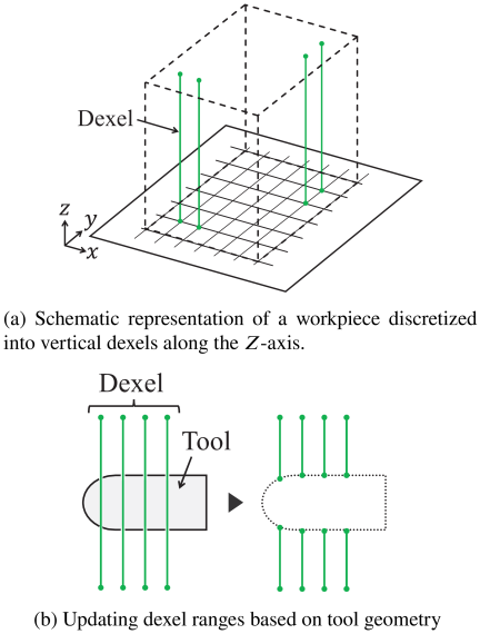
Fig. 21. Conceptual illustration of the dexel model and tool interference.
When the tool penetrates the workpiece, the endpoints of the material intervals in the \(Z\)-direction corresponding to the affected dexels are sequentially updated based on interference detection between the tool and material, as illustrated in Fig. 21(b). Furthermore, the dexel model used in this study maintained multiple material intervals in the \(Z\)-direction at each \(XY\) position.
In this section, a method is described for generating the intermediate shape obtained after roughing by eccentric-axis turning, which serves as the initial geometry of the dexel model used for air cut detection. By representing the intermediate shape as a dexel model, the workpiece geometry is maintained as a discrete set of line segments, enabling efficient evaluation and updating of material removal during subsequent machining simulation. The procedure for converting the intermediate shape obtained by eccentric-axis turning into a dexel model is as follows.
Initially, the dexels are arranged within a rectangular solid that encloses the workpiece. The intermediate shape in contrast is represented as a set of multiple cylindrical volumes, as shown in Fig. 22. For each cylindrical volume, the dexel segments located inside the material region are extracted, whereas the remaining segments are removed. This process generates a dexel model that reflects the intermediate shape.
Specifically, for each dexel arranged on the \(XY\)-plane, it is determined whether the dexel lies within the cross section of each cylindrical volume obtained by eccentric-axis turning, using the cross-sectional center and radius of the cylinder.
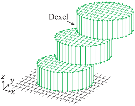
Fig. 22. Dexel model representing the intermediate shape obtained by eccentric-axis turning.
Consider dexels regularly arranged on the \(XY\)-plane, where each dexel is fixed at position \((x_i,y_j)\) and maintains a set of material intervals in the \(Z\)-direction, denoted as \(D_{ij}\). The intermediate shape after eccentric-axis turning is represented as a set of cylindrical volumes along the \(Z\)-direction, \(C=\{C_k\}\). Each cylinder \(C_k\) is defined by its cross-sectional center \((c_{x,k},c_{y,k})\), radius \(r_k\), and \(Z\)-range \([z_k^s,z_k^e]\).
A dexel at position \((x_i,y_j)\) is considered to lie within the cross section of cylinder \(C_k\) if the following condition is satisfied:
If Eq. \(\eqref{eq:17}\) holds, the dexel is considered to be located inside the material region within the \(Z\)-range \([z_k^s,z_k^e]\), and the corresponding \(Z\)-interval is registered as a material interval.
Accordingly, the material interval set reflecting the intermediate shape for dexel \((x_i,y_j)\) is expressed as
The resulting intervals are sorted along the \(Z\)-direction. If adjacent or overlapping intervals \([a,b]\) and \([c,d]\) satisfy
Using this procedure, a dexel model is generated that reflects the intermediate shape after roughing.
Next, a method for automatically detecting air cuts contained in the computed tool paths and modifying the tool paths is described. In the proposed method, each calculated tool position is regarded as a valid machining point if the tool geometry interferes with at least one dexel. Conversely, if no interference occurs with any dexel, the tool position is identified as an air cut and removed as an unnecessary motion.
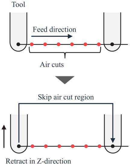
Fig. 23. Tool retraction during air cut segments.
The air cut detection process is accelerated using GPU-based parallel processing. Interference checks with multiple dexels are performed simultaneously for each tool position. Specifically, each GPU thread corresponds to a single dexel and determines whether an intersection occurs with the tool, based on the tool position and geometric parameters.
Air cut detection is conducted for all the tool positions. When the lengths of consecutive air cut segments exceed a predefined threshold, the tool is temporarily retracted in the \(Z\)-direction, and the corresponding segment is skipped, as illustrated in Fig. 23. This procedure automatically generates an NC program with effectively reduced non-cutting motions.
4. Case Study
4.1. Case Study 1
A case study was conducted to verify the effectiveness of the proposed system. In this case study, an STL-format CAD model representing an organically shaped object was used as input, and the entire analytical process—from generating the NC program for roughing by eccentric-axis turning to generating the NC programs for semi-finishing and finishing milling with reduced air cuts—was executed to confirm that the proposed system operates without issues. In addition, the case study aimed to evaluate whether applying eccentric-axis turning to the roughing stage effectively reduces machining time for organically shaped components.
For validation, an STL model representing an organically shaped object was prepared, and analyses were performed under the following three conditions:
-
I.
Milling-only machining
-
II.
Conventional turning combined with milling
-
III.
Eccentric-axis turning combined with milling
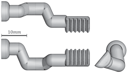
Fig. 24. CAD model used in Case Study 1.
Table 1. Tools used in the case studies.

Table 2. Machining conditions used in the case studies.

Actual machining experiments were conducted using the NC programs obtained from each analysis. The validity of the analytical results was evaluated by comparing the generated intermediate and final shapes with the corresponding machining results. The machining time reduction effect was assessed using the total machining time required for roughing and semi-finishing in each method as the evaluation metric.
The CAD model used in this case study is shown in Fig. 24. The model represents surgical robotic forceps and consists of a three-dimensionally curved, organically shaped object with an overall length of 35 mm. The geometry was designed under the assumption of multi-process machining combining eccentric-axis turning and milling, making it suitable for verifying the effectiveness of the proposed system.
Table 3. Computational environment and analysis conditions used in the case studies.

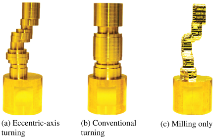
Fig. 25. Intermediate shapes after roughing for each method in Case Study 1.
For turning operations, a Swiss-type CNC automatic lathe (SR-20RIV Type B, Star Micronics Co., Ltd.) was used, and for milling operations, a POCKET NC V2-10 (Penta Machine Company) was used. A C3602 round bar with a diameter of 20.0 mm was used as the workpiece material. The cutting tools used in the case study are listed in Table 1, and the machining conditions for each process are summarized in Table 2.
The computational environment and analysis conditions used in the case studies are summarized in Table 3. The computational accuracy of the proposed system is mainly determined by the resolution used in the geometric analysis. In this study, the slicing interval for generating the contour line model was set to 0.25 mm, and the dexel interval used in the machining simulation was set to 0.25 mm. These parameters were selected so that the geometric resolution was sufficiently smaller than the tool diameter and machining allowance used in the case studies. The processing time required for shape analysis and NC program generation was 241 s for Case Study 1.
Three machining conditions were examined: eccentric-axis turning, conventional turning, and milling-only machining. The machining times were compared under these conditions. The tool path for the milling finishing process was kept identical regardless of the machining method used. In contrast, the tool path for the semi-finishing process was generated to reduce air cuts according to the intermediate shape formed by each roughing method.
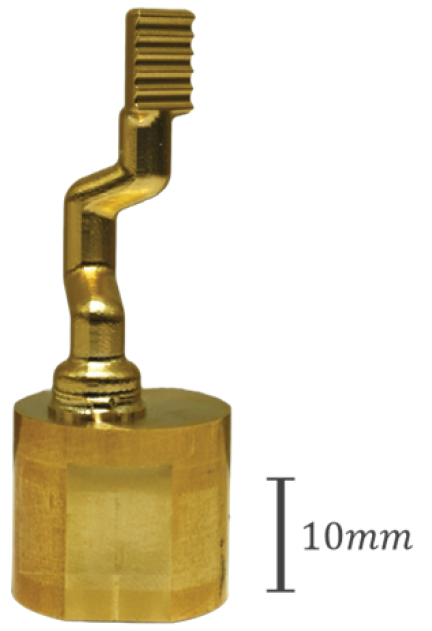
Fig. 26. Result of machined product shape in Case Study 1.
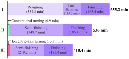
Fig. 27. Comparison of machining time for each method in Case Study 1.
The intermediate shapes obtained using each machining method are shown in Fig. 25, the final product shape is shown in Fig. 26, and the machining times are presented in Fig. 27. Because the final shapes were identical for all machining methods, only the results obtained using eccentric-axis turning are shown in Fig. 26.
Note that Fig. 27 shows the machining times for roughing, semi-finishing, and finishing. Because the tool path for the finishing process was identical for all machining methods, the reduction rates discussed here were calculated using the net machining time required for the semi-finishing process. The setup time, workpiece transfer time between machine tools, and re-chucking time were not included in this comparison.
First, the analytical results are presented. It was confirmed that the proposed system successfully extracted a set of cylindrical volumes from the STL-format three-dimensional CAD model and generated the NC program for eccentric-axis turning.
Next, the machining times are compared. As shown in Fig. 27, the total machining time required up to the semi-finishing stage was 233 min when eccentric-axis turning was applied. This represents a reduction of approximately 50.4% compared with milling-only machining, and approximately 33.5% compared with conventional turning.
These results demonstrate that applying eccentric-axis turning in the roughing stage effectively reduces the roughing time for organically shaped components.
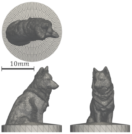
Fig. 28. CAD model used in Case Study 2.
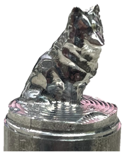
Fig. 29. Result of machined product shape in Case Study 2.
4.2. Case Study 2
To further evaluate the applicability of the proposed method to different geometries, an additional case study was conducted using another organically shaped model with geometric features distinct from those of the surgical forceps model used in Case Study 1. The CAD model used in this case study is shown in Fig. 28. The target model was an organically shaped design resembling a dog, with an overall length of 18 mm. This model was also developed under the assumption of a multi-process machining strategy that combines eccentric-axis turning and milling.
In this case study, the proposed system was applied to the entire process, from extracting the cylindrical intermediate shape for eccentric-axis turning to generating NC programs for the subsequent milling process. Unlike Case Study 1, both turning and milling operations were performed using a Swiss-type CNC automatic lathe, SR-20RIV Type B, manufactured by Star Micronics Co., Ltd. Therefore, it was not necessary to transfer the workpiece to another machine tool after the turning process, and the evaluation was conducted without machine-to-machine workpiece transfer.
The computational environment and analysis resolutions used in Case Study 2 were the same as those summarized in Table 3. The machining conditions were also set to the same values as those used in Case Study 1, as summarized in Table 2. Under these conditions, the processing time required for shape analysis and NC program generation in Case Study 2 was 525 s.
The final machined product shape is shown in Fig. 29 and the machining time is shown in Fig. 30. Fig. 30 presents the machining times for roughing, semi-finishing, and finishing. As in Case Study 1, because the finishing process was identical for all machining methods, the reduction rates were calculated using the machining time required up to the semi-finishing stage. As shown in Fig. 30, in Case Study 2, the machining time required up to the semi-finishing process was 156.8 min when eccentric-axis turning was applied. This represents a reduction of approximately 52.0% compared to milling-only machining and approximately 47.2% compared to conventional turning.
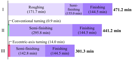
Fig. 30. Comparison of machining time for each method in Case Study 2.
The results confirmed that even for a geometry with different features from that used in Case Study 1, the proposed system could automatically extract the intermediate shape and generate tool paths and NC programs for each machining process without manual process planning. This indicates that the proposed method is not limited to a specific geometry and can be applied to other organically shaped components.
The proposed method is particularly effective for organically shaped components whose cross-sectional center positions or outer contours vary eccentrically along the longitudinal direction. For such geometries, conventional turning around the workpiece center tends to leave a large amount of remaining material after roughing, whereas eccentric-axis turning can generate an intermediate shape closer to the final product geometry. As a result, the volume of material removed during the subsequent milling process can be reduced.
However, the effectiveness of the proposed method depends on the geometric features of the target product. If the cross-sectional center positions are distributed near the rotation axis over most of the longitudinal direction, the difference between the intermediate shapes generated by conventional turning and eccentric-axis turning becomes small. In such cases, the reduction in machining time may be limited.
In addition, applying the proposed method requires a CNC multitasking lathe equipped with an eccentric-axis turning function. In other words, the method assumes the use of a machine tool capable of synchronizing spindle rotation and tool motion to machine eccentric cylindrical intermediate shapes. Therefore, the proposed method cannot be applied directly to manufacturing environments equipped with general-purpose lathes, ordinary CNC lathes without an eccentric-axis turning function, or standard three-axis machining centers.
For broader industrial applications, future work will include developing an applicability evaluation method based on the geometrical characteristics of the target product and the available machine tool configuration.
5. Conclusion
In this study an automated process planning and tool path generation method was proposed using eccentric-axis turning to reduce roughing time in the machining of organically shaped components.
In the proposed method, an intermediate shape suitable for eccentric-axis turning is automatically extracted as a set of cylindrical volumes based on the geometric analysis of an STL-format CAD model. Furthermore, by representing the intermediate shape after roughing as a dexel model, tool path generation for milling considering air cut regions was achieved.
The results of the case studies confirmed that applying eccentric-axis turning in the roughing stage reduced the machining time required up to the semi-finishing stage. In addition, actual machining based on the generated NC programs demonstrated that the intermediate and final shapes were consistent with the analytical results. For the model used in Case Study 1, the machining time was reduced by approximately 50.4% compared with milling-only machining, and by approximately 33.5% compared with conventional turning. In Case Study 2, the machining time required up to the semi-finishing stage was 156.8 min when eccentric-axis turning was applied, corresponding to a reduction of approximately 52.0% compared with milling-only machining and approximately 47.2% compared with conventional turning.
An additional case study using a model with different geometric features confirmed that the proposed method is not limited to a specific shape and can be applied to other organically shaped components. However, the effectiveness of the proposed method depends on the geometric features of the target shape. When the variation in the cross-sectional center position or outer contour relative to the rotation axis is small, the reduction in machining time may be limited. Therefore, future work should include developing a method to automatically determine the applicability of the proposed method based on the geometric features of the target shape and the available machine tool configuration.
Acknowledgments
This work was supported by JST BOOST, Grant Number JPMJBS2410 and JSPS KAKENHI (Grant Number JP25K01135).
- [1] H. Ueno, “Intelligent technology for machine tools, flexible automation,” Systems, Control and Information, Vol.61, No.3, pp. 107-112, 2017 (in Japanese). https://doi.org/10.11509/isciesci.61.3_107
- [2] Z. L. Gan, S. N. Musa, and H. J. Yap, “A review of the high-mix, low-volume manufacturing industry,” Applied Sciences, Vol.13, No.3, Article No.1687, 2023. https://doi.org/10.3390/app13031687
- [3] T. Tahmina, M. Garcia, Z. Geng, and B. Bidanda, “A survey of smart manufacturing for high-mix low-volume production in defense and aerospace industries,” Proc. of the Int. Conf. on Flexible Automation and Intelligent Manufacturing, pp. 237-245, 2022. https://doi.org/10.1007/978-3-031-18326-3_24
- [4] A. Lasemi, D. Xue, and P. Gu, “Recent development in CNC machining of freeform surfaces: A state-of-the-art review,” Computer-Aided Design, Vol.42, No.7, pp. 641-654, 2010. https://doi.org/10.1016/j.cad.2010.04.002
- [5] K. Nakamoto, K. Shirase, H. Wakamatsu, A. Tsumaya, and E. Arai, “Automatic production planning system to achieve flexible direct machining,” JSME Int. J., Series C, Vol.47, No.1, pp. 136-143, 2004. https://doi.org/10.1299/jsmec.47.136
- [6] Y. Woo, E. Wang, Y. S. Kim, and H. M. Rho, “A hybrid feature recognizer for machining process planning systems,” CIRP Annals – Manufacturing Technology, Vol.54, Issue 1, pp. 397-400, 2005. https://doi.org/10.1016/S0007-8506(07)60131-0
- [7] L. Wang, M. Holm, and G. Adamson, “Embedding a process plan in function blocks for adaptive machining,” CIRP Annals – Manufacturing Technology, Vol.59, Issue 1, pp. 433-436, 2010. https://doi.org/10.1016/j.cirp.2010.03.144
- [8] A. Ueno and K. Nakamoto, “Proposal of machining features for CAPP system for multi-tasking machine tools,” Trans. of the JSME, Vol.81, No.825, Article No.15-00108, 2015 (in Japanese). https://doi.org/10.1299/transjsme.15-00108
- [9] H. Sakurai, “Volume decomposition and feature recognition: Part 1—polyhedral objects,” Computer-Aided Design, Vol.27, Issue 11, pp. 833-843, 1995. https://doi.org/10.1016/0010-4485(95)00007-0
- [10] H. Sakurai and P. Dave, “Volume decomposition and feature recognition: Part 2—curved objects,” Computer-Aided Design, Vol.28, Issues 6-7, pp. 519-537, 1996. https://doi.org/10.1016/0010-4485(95)00067-4
- [11] E. Morinaga, M. Yamada, H. Wakamatsu, and E. Arai, “Flexible process planning method for milling,” Int. J. Automation Technol., Vol.5, No.5, pp. 700-707, 2011. https://doi.org/10.20965/ijat.2011.p0700
- [12] E. Morinaga, T. Hara, H. Joko, H. Wakamatsu, and E. Arai, “Improvement of computational efficiency in flexible computer-aided process planning,” Int. J. Automation Technol., Vol.8, No.3, pp. 396-405, 2014. https://doi.org/10.20965/ijat.2014.p0396
- [13] K. Dwijayanti and H. Aoyama, “Basic study on process planning for turning-milling center based on machining feature recognition,” J. of Advanced Mechanical Design, Systems and Manufacturing, Vol.8, No.4, Article No.JAMDSM0058, 2014. https://doi.org/10.1299/jamdsm.2014jamdsm0058
- [14] I. Nishida and K. Shirase, “Automatic determination of cutting conditions for NC program generation by reusing machining case data based on geometric properties of removal volume,” J. of Advanced Mechanical Design, Systems and Manufacturing, Vol.12, No.4, Article No.JAMDSM0093, 2018. https://doi.org/10.1299/jamdsm.2018jamdsm0093
- [15] P. Kosec, I. Huic, T. Martinec, and S. Škec, “Exploring generative design in context of mass personalization,” Proc. of the Design Society, Vol.5, pp. 1665-1674, 2025. https://doi.org/10.1017/pds.2025.10180
- [16] M. J. Dewey, R. S. H. Chang, A. V. Nosatov, K. Janssen, S. J. Crotts, S. J. Hollister, and B. A. C. Harley, “Generative design approach to combine architected Voronoi foams with porous collagen scaffolds to create a tunable composite biomaterial,” Acta Biomaterialia, Vol.172, pp. 249-259, 2023. https://doi.org/10.1016/j.actbio.2023.10.005
- [17] J. Zhu, M. Kato, T. Tanaka, H. Yoshioka, and Y. Saito, “Graph based automatic process planning system for multi-tasking machine,” J. of Advanced Mechanical Design, Systems and Manufacturing, Vol.9, No.3, Article No.JAMDSM0034, 2015. https://doi.org/10.1299/jamdsm.2015jamdsm0034
- [18] Y. Inoue and K. Nakamoto, “Development of a CAPP system for multi-tasking machine tools to deal with complicated machining operations,” J. of Advanced Mechanical Design, Systems and Manufacturing, Vol.14, No.1, Article No.JAMDSM0006, 2020. https://doi.org/10.1299/jamdsm.2020jamdsm0006
- [19] N. Date, P. Krishnawami, and V. V. S. K. Motipalli, “Automated process planning method to machine a B-spline free-form feature on a mill–turn center,” Computers & Industrial Engineering, Vol.56, Issue 1, pp. 198-207, 2009. https://doi.org/10.1016/j.cie.2008.05.004
- [20] T. Muraki and H. Yamamoto, “Current state and outlook of the multi-tasking machine,” J. of the Japan Society for Precision Engineering, Vol.78, No.9, pp. 740-743, 2012 (in Japanese). https://doi.org/10.2493/jjspe.78.740
- [21] R. Takamori, H. Nakatsuji, and I. Nishida, “Automated process planning system to machine organic shapes by combining turning and milling,” J. of Advanced Mechanical Design, Systems, and Manufacturing, Vol.18, Issue 4, Article No.JAMDSM0038, 2024. https://doi.org/10.1299/jamdsm.2024jamdsm0038
- [22] H. Zhou, B. Henson, and X. Wang, “Extracted control approach for CNC non-circular turning,” Asian J. of Control, Vol.7, No.1, pp. 50-55, 2005. https://doi.org/10.1111/j.1934-6093.2005.tb00227.x
- [23] Z. Sun and T.-C. Tsao, “Process feedback control of the noncircular turning process for camshaft machining,” J. of Dynamic Systems, Measurement, and Control, Vol.130, No.3, Article No.031006, 2008. https://doi.org/10.1115/1.2907403
- [24] Y. Zhang, H. Lu, X. Zhang, W. Fan, X. Su, H. Ling, and S. Wang, “Spiral tool path generation based on symbolic computation for machining of non-axisymmetric curved surface,” The Int. J. of Advanced Manufacturing Technology, Vol.91, pp. 3911-3924, 2017. https://doi.org/10.1007/s00170-017-0059-x
- [25] I. Nishida, E. Yamada, and H. Nakatsuji, “Automated process planning system for machining injection molding dies using CAD models of product shapes in STL format,” Int. J. Automation Technol., Vol.17, No.6, pp. 619-626, 2023. https://doi.org/10.20965/ijat.2023.p0619
- [26] M. Inui, T. Sakurai, and N. Umezu, “Data conversion technology between triple dexel model and polygonal model,” J. of the Japan Society for Precision Engineering, Vol.76, No.2, pp. 226-231, 2010 (in Japanese). https://doi.org/10.2493/jjspe.76.226
- [27] M. Inui and N. Umezu, “Contour-type cutter path computation using ultra-high-resolution dexel model,” Computer-Aided Design and Applications, Vol.17, No.3, pp. 621-638, 2020. https://doi.org/10.14733/cadaps.2020.621-638
- [28] M. Inui, “Visualization of machined shape in 3+2-axis machining by triple-dexel integration of multiple z-map models,” Proc. of the 18th Int. Conf. on Manufacturing Research, pp. 413-418, 2021.
This article is published under a Creative Commons Attribution-NoDerivatives 4.0 Internationa License.