
Research Paper:
Development of a Tactile Globe Maker for the Visually Impaired —Taglomal, the Spherical Surface Processing Machine—
Naoki Asakawa*,†
 , Tomoki Hidai*, Yuko Shimomura*, Hiroki Wada**, and Keigo Takasugi*
*Kanazawa University
Kakuma-machi, Kanazawa, Ishikawa 920-1192, Japan
†Corresponding author
**Kinjo College
Hakusan, Japan

This study aims to automate the production of globes for the visually impaired (VI) and provide low-cost alternatives. This process is achieved using a spherical surface processing machine dedicated to globe fabrication, equipped with a two-axis rotary positioning mechanism and a semiconductor laser. The machine operates based on machining paths generated by a custom-developed computer-aided manufacturing system specifically designed for globe production. As the system generates tool paths from geopolitical information, it supports a variety of applications beyond conventional drilling. These include the creation of raised solid borders, the addition of textures using small point clouds applied exclusively to land areas, and the merging of small-area countries with larger neighboring countries. This allows users to obtain globes tailored to their specific purposes and preferences. As a result, the developed processing system is capable of automatically producing customized globes for VI individuals within one day. In an experiment conducted to investigate which globe characteristics were preferred by several VI participants, no single design was found to be universally preferred. This finding indicates the effectiveness of the proposed system, as it enables customization according to individual user preferences.
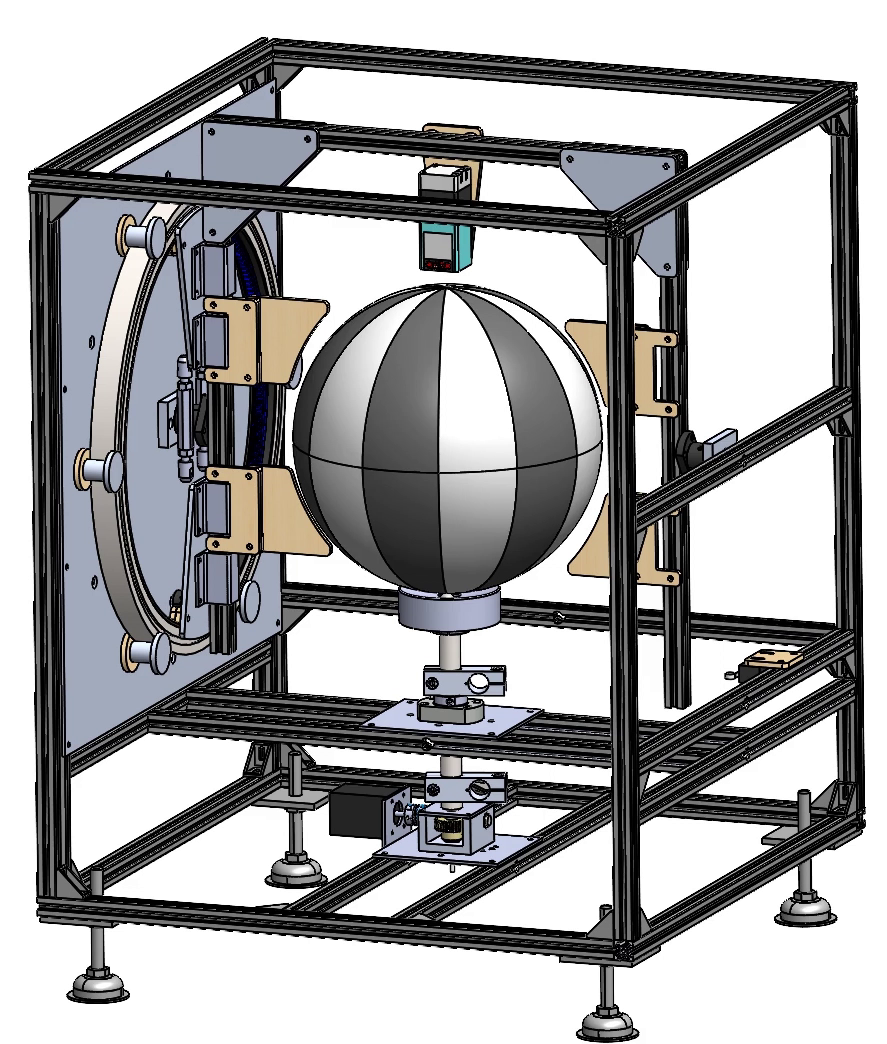
Structure of Taglomal – the spherical surface processing machine
1. Introduction
Visually impaired (VI) individuals rely on tactile materials to acquire information through the sense of touch. In the context of geography education, tactile maps serve as a primary resource; these maps are designed with raised lines and Braille to convey spatial information. A variety of tactile maps have been developed for different applications, including simplified world maps and navigational maps for routes such as those leading to train stations. Additionally, numerous systems have been introduced to support the design and production of tactile maps 1.
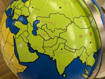
Fig. 1. Tactile globe produced by Sun Kogei.
On the other hand, the globe constitutes an indispensable tool in geography education. The Japanese school curriculum guidelines encourage the use of globes in instructional settings 2. Experimental studies by Baldy involving children suggest that some learners may struggle to understand the correspondence between maps and globes 3, a challenge that is likely to extend to VI individuals. Therefore, while the globe remains an essential educational resource, its design must be adapted to meet the needs of VI learners. Specifically, a tactile globe intended for the study of geopolitics should incorporate raised borders to delineate boundaries and Braille labels to represent country names, thereby enabling effective tactile recognition. Therefore, globes that represent only topographical elevation through protruding landforms are insufficient for this purpose 4. The globe produced by Sun Kougei features raised projections along borders and conveys place names in Braille, as shown in Fig. 1. Although this globe is preferred by schools for the blind across Japan, it is not commercially available due to the difficulty of mass production. In addition, owing to the limited surface area of the globe, the amount of information that can be conveyed in Braille is restricted, and in some cases, information may be omitted 5. One approach to increasing the amount of information is to enlarge the globe; however, this also presents a challenge for mass production 6. Furthermore, because only approximately 10% of VI individuals can read Braille, alternative methods of information transmission are preferred 7. One such method is the use of audio-guided globes; however, most existing audio-guided globes are not designed for use by VI individuals. For such globes to be accessible to VI users, they must incorporate raised surface features to indicate borders and coastlines 8,9.
There are several possible approaches to incorporating projections into an audio-guided globe. One method involves covering the globe with an uneven plastic layer, which is relatively easy to implement. However, this approach is inefficient when customizability, such as that needed for tactile maps, is important 10. The cross-sensory globe developed by Ghodke et al. employs continent-shaped components produced by additive manufacturing, which are attached to the globe’s surface using magnets. As a result, spatial understanding is limited to the continental scale, and additional components must be created and attached to represent information at the national scale 11. On the other hand, Reha Vision has developed a globe in which round-headed pins are inserted into holes drilled along coastlines, allowing the outline of the coastline to be recognized through these pins. The globe is shown in Fig. 2 12. Although this product is preferred by VI individuals, it is difficult to purchase because it is handmade, and delivery takes approximately three months after an order is placed. If the process of attaching projections along borders, including numerical positioning, could be automated, mass production would become feasible, enabling wider use by VI individuals in classrooms and other settings. Moreover, if customized processing based on world map data becomes possible, the overall utility of the globe would be enhanced.
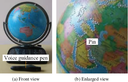
Fig. 2. Tactile globe produced by Reha Vision.
The first step in automating the machining of a tactile globe is the automation of the drilling process along borders. Automatic drilling of holes along borders fundamentally involves numerical positioning and drilling on a spherical workpiece. In such cases, machine tools with a high degree of freedom, such as five-axis machine tools, are typically employed. However, these systems are large and expensive to install. In contrast, when developing a machine specialized for spherical machining, a positioning mechanism with three degrees of freedom based on a polar coordinate system is sufficient. Furthermore, to produce a variety of globes tailored to user needs, it is necessary to develop software capable of automatically generating machining paths for spherical surface machining machines based on publicly available geopolitical information, such as national borders. In our previous paper 13, a computer-aided manufacturing (CAM) system for an industrial robot was developed to calculate target points for machining, and these points were successfully marked on the surface of a sphere. However, industrial robots present challenges such as large size and low absolute positioning accuracy, which make it difficult to perform actual drilling operations.
In this paper, a spherical surface machining machine equipped with a two-axis rotary positioning mechanism was developed as a specialized system for drilling in the production of tactile globes. Furthermore, to enable the automatic production of customized globes according to the needs of VI individuals, a dedicated CAM system that generates machining paths based on geopolitical information was developed.
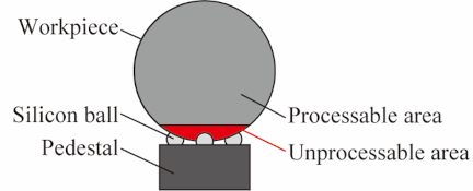
Fig. 3. Method for holding the spherical workpiece.
2. Spherical Surface Machining Machine
2.1. Required Specifications and Machine Concept
As the countries printed on the surface of a globe may not correspond to border lines processed based on geopolitical information, this system employs spheres without maps as workpieces. Accordingly, an original audio guidance system applicable to a map-free globe was developed; however, this study does not address the audio guidance system. Based on the dimensions of commercially available globes, the workpiece sphere was specified to have a diameter of 300 mm. For practical use, the workpiece is designed as a spherical shell composed of two domed parts. When machining a sphere using a five-axis machine tool, a core rod is attached to the sphere to enable secure holding by the machine. However, in the context of globe machining, it is more efficient to directly contact and support the sphere surface rather than inserting and holding a core rod. Therefore, the holding method shown in Fig. 3 is adopted. In this method, the workpiece is placed on a pedestal supported by three silicon balls and is neither mechanically clamped nor adsorbed. With this holding approach, the workpiece must be positioned during the machining of Antarctica. However, considering the relatively limited importance of Antarctica in typical globe use, the Antarctic is not included in the machining scope of this project. By excluding Antarctica from processing, this workholding method enables machining over a wide area in a single setup.
Two issues arise when drilling holes using this workpiece holding method. The first concerns contact between the tool and the workpiece during drilling. When drilling a hole with a drill, the workpiece must be firmly secured; alternatively, the hole must be produced using a non-contact method. The second issue is that the workpiece is not a true sphere, as it is not manufactured through precision processes such as milling. Specifically, the diameter of the spheres can vary by up to 6 mm. Therefore, the distance between the workpiece and the tool varies during operation. Accordingly, a mechanism is required to accommodate changes in this distance, such as a system capable of moving the sphere in the radial direction. To address these two issues, a laser is employed as the drilling tool. The use of a laser enables machining without physical contact between the tool and the workpiece. Furthermore, even if the distance between the tool and the workpiece varies, drilling can still be performed provided that the laser energy density remains sufficient.
The concept of this machine is based on a holding method that does not require the attachment of a core rod to the sphere, combined with non-contact drilling using a laser.
2.1.1. Positioning Mechanism
When drilling on a spherical surface, it is necessary to position the tool along the normal direction of the sphere. The concept of this study is to achieve this using only the minimum required two-axis rotary positioning mechanism. If a two-axis rotary mechanism were assigned entirely to either the tool or the workpiece, one rotary axis would need to be nested within the other, resulting in a requirement for a large driving force. Therefore, one rotational axis is assigned to the tool and the other to the workpiece. Considering that the workpiece is merely placed on the pedestal, the workpiece is assigned rotation in the latitudinal direction, while the tool is assigned rotation in the longitudinal direction, as shown in Fig. 4.
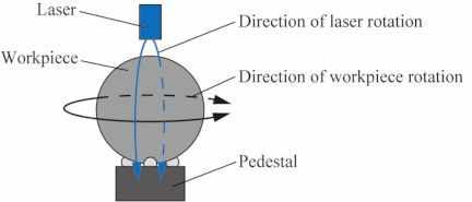
Fig. 4. Rotational directions of the workpiece and the laser.
The spherical surface machining machine developed based on the structure described above is shown in Fig. 5(a). This machine has been named Taglomal (short for tactile globe maker by laser). The two rotational mechanisms incorporated in Taglomal are driven by stepper motors, as shown in Fig. 5(b). A worm gear is employed for the workpiece rotation mechanism, while a combination of a large internal gear and a pinion gear is used for the tool rotation mechanism. The purpose of this design is to reduce the driving force required to rotate the mechanisms and to improve the resolution of the system. The internal gear is constructed by attaching a flexible plastic rack to the inner ring of a large bearing. The theoretical resolution of each mechanism is 0.109°/step for the workpiece rotation mechanism and 0.138°/step for the tool rotation mechanism. Given that the diameter of the workpiece is approximately 300 mm, the corresponding linear resolution is 0.286 mm/step at the equator for the workpiece rotation mechanism and 0.362 mm/step for the tool rotation mechanism. Because the diameter of the pin head to be inserted into the hole is 1.6 mm, this resolution is considered sufficient for the intended application.
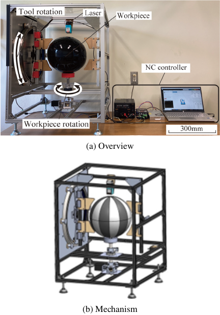
Fig. 5. Spherical surface machining machine “Taglomal.”
2.1.2. Laser
As the laser unit moves around the workpiece, it must be lightweight and compact. Moreover, as the workpiece is made of acrylic, the laser must be capable of processing plastic materials. Therefore, two types of semiconductor lasers are employed: a 5.5 W laser for drilling and a 1.6 W laser for other processing tasks. Both lasers operate at a wavelength of 445 nm.
2.2. Machine Control System
The stepping motors and semiconductor lasers of Taglomal are controlled via a control board (CNC xPRO V5), which operates based on G-code commands input into the control software (CNCjs). Processing conditions are adjusted by varying parameters such as laser irradiation time, travel speed, and input voltage.
2.3. Positioning Accuracy
2.3.1. Outline of Experiment
To evaluate the accuracy of the positioning mechanism, a rotary encoder (Omron E6A2-CWZ3C) was attached to the central axis of the mechanism to measure the difference between the commanded value and the actual displacement. The rotary encoder has 500 pulses per revolution (PPR), and the number of cycles per revolution (CPR) is 2000, which is four times the PPR. Accordingly, the angular resolution of the rotary encoder is 0.18°. All positioning speeds were set to 1.0 min\(^{-1}\).
2.3.2. Workpiece Rotation Mechanism
The workpiece rotation mechanism was evaluated for misalignment during unidirectional rotation and during bidirectional motion at 30° intervals. The misalignment results for each rotation direction are shown in Fig. 6. The maximum misalignment observed during unidirectional rotation was 0.3°, corresponding to 0.79 mm on the spherical surface, which is sufficiently accurate relative to the diameter of the pin head. The left-right difference observed in Fig. 6(b) indicates misalignment arising from differences in the rotational direction during positioning. This effect is attributed to gear backlash, with a maximum value of 0.18°, corresponding to 0.47 mm on the spherical surface. These results indicate that bidirectional motion does not pose a problem for spherical surface machining.
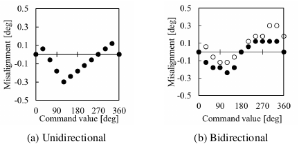
Fig. 6. Positioning accuracy of the workpiece rotation mechanism.
2.3.3. Tool Rotation Mechanism
The tool rotation mechanism was also evaluated for misalignment during unidirectional and bidirectional rotation at 30° intervals. As the lasers were mounted at approximately equal distances from the left and right axes of rotation, rotary encoders were attached to each axis, and the average of the measurements was used as the representative value for the laser position. As shown in Fig. 7(a), the maximum misalignment during unidirectional rotation was 0.33°, corresponding to 0.86 mm on the spherical surface, which is sufficiently accurate relative to the diameter of the pin head. The maximum misalignment due to gear backlash was 0.18°, as shown in Fig. 7(b). This corresponds to 0.47 mm on the spherical surface and is not considered to affect the machining of a sphere during bidirectional motion.
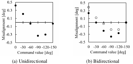
Fig. 7. Positioning accuracy of the tool rotation mechanism.
2.4. Laser Processing Accuracy
The workpiece is not a perfect sphere, and the distance between the laser unit and the workpiece varies with latitude. As the hole diameter changes with this variation in distance, the relationship between hole diameter and distance was investigated through basic experiments. Fig. 8 shows an example of the results obtained using a 5.5 W laser unit. The acceptable tolerance range for the diameter of the processed hole is 0.6–0.8 mm; therefore, the position of the laser unit was determined based on these experimental results. During processing, an appropriate hole diameter could be achieved by fine-tuning the laser intensity according to latitude.
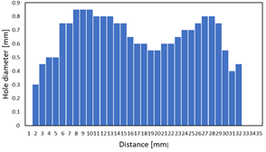
Fig. 8. Relationship between distance and hole diameter.
3. CAM
3.1. Import of Global Border Point Cloud Data
The CAM system developed in this study is referred to as Globe CAM. Globe CAM was developed based on Kodatuno, an open-source CAM kernel. It was originally designed for producing globes for VI individuals using industrial robots; therefore, it has been further customized for use with Taglomal 13,14. Globe CAM generates machining paths using publicly available geopolitical data. Specifically, it utilizes global border point cloud data in the public domain provided by Natural Earth 15. These data, referred to as shape data, represent the borders and coastlines of countries worldwide as sets of latitude and longitude coordinate points. Within the shape data, points are organized into polygons corresponding to geographical entities such as countries and islands, and the points of each polygon are stored in clockwise order. As the spacing of points in the dataset is significantly denser than the required hole interval for processing on the sphere, the data are reduced at specified intervals before being used for machining.
3.2. Thinning of Points
3.2.1. Equal Interval Method
The simplest approach for thinning the point data is to preserve points at equal intervals while deleting the remaining points. In the equal interval method, the desired spacing between points is specified in advance, and points from the shape data are retained for each polygon according to this interval. When multiple polygons overlap, only one representative point is retained. As a result, a set of uniformly spaced points is generated, as shown in Fig. 9(a). The spacing between points can be flexibly adjusted, ranging from a minimum of 1.6 mm (corresponding to the diameter of the pin head) to several millimeters, depending on user requirements.
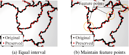
Fig. 9. Point cloud thinning methods.
3.2.2. Feature Point Preservation Method
Although the equal interval method is simple, it may result in the loss of characteristic features of the polygon. In this context, characteristic features refer to abrupt changes along the boundary. To address this issue, a feature point preservation method is employed 16. In this method, rather than removing points at fixed intervals, the shape is preserved by representing straight segments with fewer points and curved regions with a higher density of points. Additionally, overlapping points, such as those along national borders, are not preserved. Through this approach, a thinned point cloud is generated while preserving key geometric features, as shown in Fig. 9(b). The spacing between points can also be flexibly adjusted using this method, ranging from the size of the pin head to several millimeters.
3.3. Generation of Toolpath
3.3.1. Dotted Border Method
A toolpath for machining is generated using the point cloud obtained by reducing the original shape data through one of the methods described above. Toolpaths for drilling holes at all points are generated by creating commands that control the two rotary mechanisms based on the coordinates of the processing points and by irradiating the laser for a specified duration. The laser processing procedure is illustrated in Fig. 10. To improve the positional accuracy of border machining, it is preferable to restrict the rotational direction of the two-axis rotary mechanism to a single direction. However, this approach is inefficient in terms of machining time. As it has been verified that sufficient positioning accuracy can be achieved even during bidirectional motion, the machining sequence follows the order of the polygons as stored in the original dataset. As the thickness of the workpiece varies with latitude—being thinner at higher latitudes and thicker at lower latitudes—the laser irradiation time is adjusted accordingly. The appropriate irradiation time is determined through preliminary experiments within the range of 0.4–1.2 s.
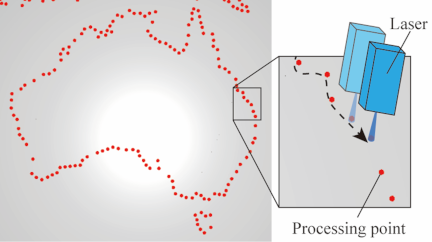
Fig. 10. Toolpath for processing dotted borders.
3.3.2. Solid Border Method
The first application that enhances the customizability of globes produced by this system is the solid border method. As shown in Fig. 11, when the workpiece is irradiated with a laser while being moved, the molten material is deposited around the processed area. By utilizing material deposition phenomenon, a raised, solid border can be formed. As shown in Fig. 12, Taglomal moves the laser unit while continuously irradiating along a point cloud representing national borders. Through this motion, material deposits are generated along the trajectory, forming raised features that represent national boundaries on the surface of the workpiece.
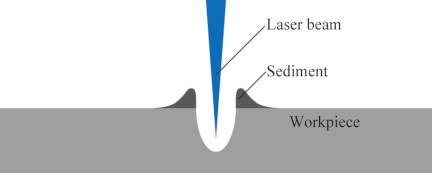
Fig. 11. Material deposition generated by laser irradiation.
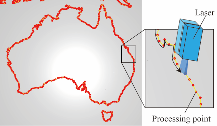
Fig. 12. Toolpath for solid border processing.
3.3.3. Texturing on Land or Sea Areas
Even when VI individuals can recognize areas by touching raised borders, they may not be able to distinguish whether the region represents land or sea. To enable intuitive identification without relying on audio guidance, different textures are applied to land and sea areas. Specifically, either land or sea regions are dotted at equal intervals. To distinguish between land and sea, reverse geocoding is employed to obtain address information from latitude and longitude coordinates. As latitude and longitude values are sequentially updated, reverse geocoding is performed using GeoPy to search for corresponding addresses 17. If an address is successfully identified, the coordinate is classified as land; otherwise, it is classified as sea. Based on this process, a lookup table is generated to indicate whether specific coordinates correspond to land or sea. Globe CAM then utilizes this information to generate toolpaths that apply dot patterns to the designated regions.
3.3.4. Merging Small Countries Into Larger Ones
It is difficult to convey information about countries with small areas to VI individuals through tactile perception. Even when a highly detailed globe is produced, it is often challenging for VI users to accurately identify all countries. For understanding finer geographical details, partially enlarged tactile maps are more suitable than tactile globes. Accordingly, a function has been implemented to generate globes that omit certain countries, such as those with small land areas. Based on a prepared correspondence table of country names and their respective areas, countries that do not satisfy specified criteria are merged with neighboring countries that satisfy these conditions. Specifically, among the points constituting the two countries to be merged, those whose mutual distances are below a defined threshold are identified as boundary points and subsequently removed. For example, Portugal, which has a relatively small land area, is merged with the adjacent country, Spain. This process is applied to all omitted countries, after which toolpaths are generated to process the resulting point clouds as either dotted or solid borders.
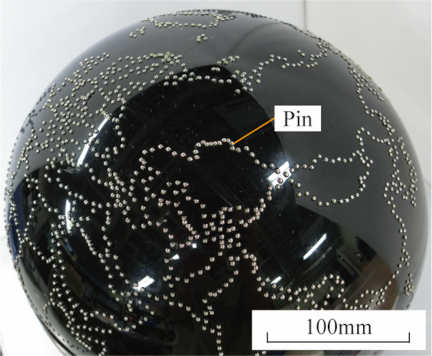
Fig. 13. Dotted border globe drilled with Taglomal.
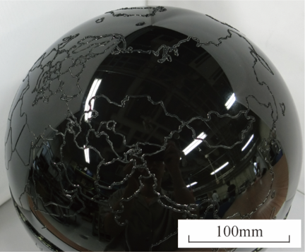
Fig. 14. Solid-border globe fabricated using Taglomal.
4. Creating a Tactile Globe
The drilling process for the globe using the point border method, as shown in Fig. 13, was completed in approximately 2 h. Pins were then manually inserted into the holes created automatically by Taglomal. If a hole was larger than the pin shaft diameter, adhesive was applied; if it was smaller, a hammer was used to press-fit the pin. This insertion process required approximately 4 h for the region shown in Fig. 13. Although pin insertion remains a manual operation, the required time and effort are significantly reduced compared to a fully manual production process. In contrast, the globe produced using the solid border method, shown in Fig. 14, was completed in less than 2 h. This globe can be produced only through automated machining using Taglomal. The height of the raised borders exceeds 0.3 mm, which is lower than the height of the pin head (0.8 mm), but remains sufficiently high for VI individuals to perceive with their fingertips, as it satisfies the Braille height standards recommended in Japan 18. The production of the globe with surface texturing, as shown in Fig. 15, required approximately 6 h. The creation of the globe with small countries omitted required approximately 2 h. Fig. 16(a) shows the original toolpath, whereas Fig. 16(b) shows the toolpath with small countries omitted.
Either method enables the completion of a tactile globe within a single day, suggesting that the lead time can be significantly reduced through automated processing.
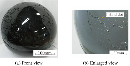
Fig. 15. Globe with textured inland regions.
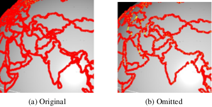
Fig. 16. Globe with small countries omitted.
5. Feedback from VI Users
Based on feedback from 19 participants (9 blind and 10 low-vision individuals), a dotted border with a pronounced convex profile was preferred in most cases. Several participants also indicated that combining multiple processing methods would increase the variety and usability of the borders. In response to this feedback, a globe was produced in which coastlines were represented using dotted borders, while other boundaries were formed using solid borders. These results demonstrate that the system developed in this study is capable of producing globes tailored to the diverse needs of users.
Regarding the globes with land and sea texturing, seven visually impaired participants reported that the textures facilitated easier distinction between land and sea. However, opinions varied as to whether textured regions should represent land or sea, indicating that the preferred configuration depends on individual user preferences. These findings highlight the importance and usefulness of customization for each user.
Additional feedback was obtained from teachers at the Ishikawa Prefectural School for the Blind. Their request for a globe featuring only major countries was addressed by producing a globe in which smaller countries were merged into larger ones. Furthermore, they expressed additional needs, including a color-enhanced globe suitable for low-vision users and a puzzle-based globe for interactive geography learning. Future work will focus on expanding the globe processing system to accommodate these educational requirements.
6. Conclusion
A system for automating the production of globes for VI individuals was developed using Taglomal, a spherical surface milling machine equipped with a two-axis rotary positioning mechanism and a semiconductor laser, in conjunction with Globe CAM, which automatically generates machining paths from geopolitical information. The main results are summarized as follows:
-
The processing of dotted borders, which was previously performed manually, was successfully automated.
-
New processing methods, including solid border processing, texture processing, and the merging of small countries, were developed, enabling a highly customizable system.
Acknowledgments
The authors would like to thank the staff and users of the Ishikawa Information and Culture Center for the Visually Impaired and the staff and students at the Ishikawa Prefectural School for the Blind for their evaluation and advice on the globe.
- [1] B. Taylor, A. Dey, D. Siewiorek, and A. Smailagic, “Customizable 3D printed tactile maps as interactive overlays,” Proc. 18th Int. ACM SIGACCESS Conf. Comput. Accessibility (ASSETS’16), pp. 71-79, 2016. https://doi.org/10.1145/2982142.2982167
- [2] Ministry of Education, Culture, Sports, Science and Technology, “Revised Courses of Study for 2017, 2018, and 2019 (text and commentary).” https://www.mext.go.jp/a_menu/shotou/new-cs/1384661.htm [Accessed September 24, 2024]
- [3] E. Baldy, “Children’s representation of the Earth at the end of elementary school: The role of spherical and geographical information carried by the globe,” Rev. Sci. Math. ICT Educ., Vol.17, No.2, pp. 5-25, 2023. https://doi.org/10.26220/rev.4479
- [4] Räthgloben, “3D-Leuchtglobus FRI 30 15.” https://www.raethgloben.de/kollektionen/raethgloben-leipzig/relief-leuchtglobus-fri-30-15 [Accessed September 24, 2024].
- [5] Sun Kogei Co. Ltd., “Barrier-free globe.” http://www.sunkogei.co.jp/history/ [Accessed September 24, 2024]
- [6] Perkins School for the Blind, “Touching history.” https://www.perkins.org/touching-history/ [Accessed September 24, 2024]
- [7] Braille Works, “Braille literacy statistics and how they relate to equality.” https://brailleworks.com/braille-literacy-statistics/.
- [8] Doshisha Co. Ltd., “Perfect globe.” http://perfectglobe.net/ [Accessed September 24, 2024]
- [9] Ceciaa, “Globe terrestre tactile avec stylo parlant.” https://www.ceciaa.com/globe-terrestre-tactile-avec-stylo-parlant.html [Accessed September 24, 2024]
- [10] American Printing House, “Tactile world globe.” https://www.aph.org/product/tactile-world-globe/ [Accessed September 24, 2024]
- [11] U. Ghodke, L. Yusim, S. Somanath, and P. Coppin, “The cross-sensory globe: Participatory design of a 3D audio-tactile globe prototype for blind and low-vision users to learn geography,” Proc. 2019 Designing Interactive Systems Conf. (DIS’19), pp. 399-412, 2019. https://doi.org/10.1145/3322276.3323686
- [12] Reha Vision Co. Ltd., “Talking globe.” http://www.y-adagio.com/public/committees/vhis/confs/vhis5/vhis5-4.pdf [Accessed September 24, 2024]
- [13] N. Asakawa, R. Kito, and K. Takasugi, “Development of tactile globe for the visually impaired (automation of marking using an industrial robot),” Int. J. Automation Technol., Vol.11, No.2, pp. 270-277, 2017. https://doi.org/10.20965/ijat.2017.p0270
- [14] K. Takasugi, N. Asakawa, and Y. Morimoto, “A surface parameter based method for accurate and efficient tool path generation,” Int. J. Automation Technol., Vol.8, No.3, pp. 428-436, 2014. https://doi.org/10.20965/ijat.2014.p0428
- [15] Natural Earth, “Downloads.” https://www.naturalearthdata.com/downloads/ [Accessed September 24, 2024]
- [16] S. Kato, K. Onishi, and Y. Ishida, “Interpolated point thinning method for digital maps according to scale,” Proc. IPSJ 46th National Convention, 8Q-8, 1993 (in Japanese).
- [17] GeoPy, “Welcome to GeoPy’s documentation!” https://geopy.readthedocs.io/en/stable/ [Accessed September 24, 2024]
- [18] Japan Braille Commission, “Braille in Japan No.23.” http://www.braille.jp/_files/00005388/nihontenji23.pdf [Accessed September 24, 2024]
This article is published under a Creative Commons Attribution-NoDerivatives 4.0 Internationa License.