
Research Paper:
Center of Gravity Detection of Crane Load Using Lifting Force Sensor and Depth Camera on Hook
Yuma Nishida, Hiroaki Seki†
 , Tokuo Tsuji
, and Tatsuhiro Hiramitsu
, Tokuo Tsuji
, and Tatsuhiro Hiramitsu
Institute of Science and Engineering, Kanazawa University
Kakuma-machi, Kanazawa, Ishikawa 920-1192, Japan
†Corresponding author

When lifting a load using a crane, it must be hoisted directly above its center of gravity (COG) to prevent tilting and swinging, which can lead to serious accidents. Therefore, accurately identifying the COG before lifting is essential for crane safety and is a key technology for crane-lift automation. Although many methods exist for measuring the COG after the load is lifted, they often fail to prevent potential risks. Therefore, for loads with a rectangular bottom, we propose and develop a sensor system capable of detecting COG “before” the load is lifted. A depth camera and a lifting force sensor are mounted on a crane hook. The lifting force sensor also functions as a spring, allowing the lifting force to increase gradually when a crane wire is wound. The direction of the tilting of the load, that is, the direction of the COG, is detected from the change in the depth image of the top surface of the load when the load is lifted only slightly. The horizontal distance to the COG is determined by observing the changes in the lifting force, which varies before and after any edge of the load bottom is slightly lifted. Unless the COG of the load is directly beneath the lifting position, the load typically tilts toward one of the four edges of the rectangular bottom. Subsequently, to determine the COG in a two-dimensional plane, two lifting trials are required when the weight of the load is known, whereas three trials are required if the weight is unknown. Experiments were conducted to detect the COG of loads, confirming the effectiveness and sufficient accuracy of the proposed detection method.
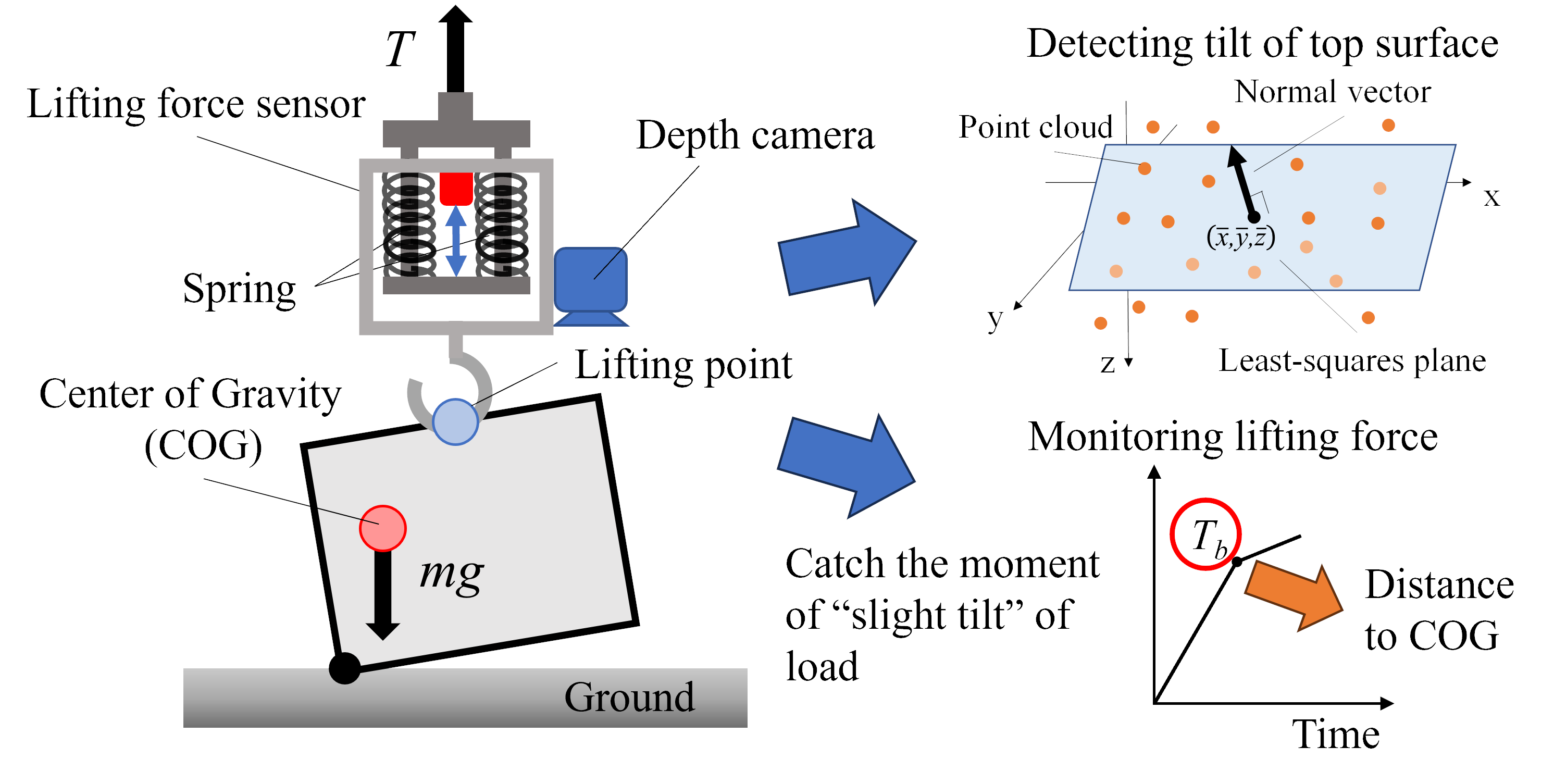
COG detection system using lifting force sensor and depth camera
1. Introduction
Cranes are indispensable in construction sites, ports, warehouses, and factories. However, as they primarily lift heavy loads using a single wire, they are unstable and prone to frequent accidents 1. Approximately one-third of all serious construction accidents involve cranes 2. Therefore, extensive research and development efforts have focused on improving safety by controlling the load swing and monitoring collisions with the surroundings after lifting a load 3,4,5,6. In recent years, efforts have been made to advance crane-lift automation at various sites 7,8, and the safety technologies have become indispensable.
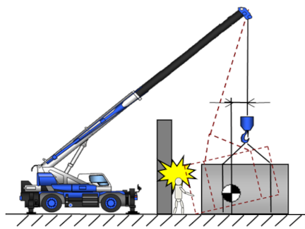
Fig. 1. Schematic depicting the risk of crane accidents due to misalignment between the lifting position and the COG.
The crane must lift its load directly above its center of gravity (COG). This is fundamental for the stable lifting of the load. If the lifting position and COG are misaligned horizontally, the load tilts or sways upon lifting, thereby increasing the risk of serious accidents, as shown in Fig. 1. When the COG of a load is unclear, workers typically proceed with caution and gradually repeat the lifting process to observe any tilting or displacement/tension in the lifting wire. This process is labor-intensive and heavily dependent on workers’ experience and skills.
The simplest method for determining the COG of a load is to place it on the load cell plate and measure the balance of forces at the four corners 9. Similarly, the four corners of the load are lifted by wires and their tension balance can be measured 10. However, this method requires the load to be fully lifted, which is often too late. If the COG is misaligned with the lifting point, it poses significant safety risks.
In the automotive field, various COG detection methods have been explored, including weigh-in-motion technology, which examines the relationship between the instantaneous effective radius of a tire and the load applied to the tire 11,12. Many other methods estimate the COG positions by analyzing the vibration and acceleration behavior of a vehicle 13,14. Similar methods are employed to evaluate the roll-over risks of humanoid and mobile robots 15. Crane loads cannot be accelerated or oscillated prior to lifting, making these methods inapplicable. In robotic manipulation, COG detection has been explored using grasp-less manipulation with a robotic hand 16,17. The COG is estimated based on the statics relationships between the grasping forces of the fingers when the object is tilted in various directions. Although this method is not directly applicable to crane loads, static analysis provides valuable insights.
Accordingly, we propose a sensor system that detects the COG of a load “before” the load is completely lifted off the ground. A depth image of the top surface of the load is used to determine the direction of the COG relative to the lifting position, and the lifting force is used to estimate the horizontal distance to the COG.
2. Proposed COG Detection Method
2.1. COG Detection System
The bottom of the load was assumed to be rectangular, and the dimensions of the load, including the lifting position, were known. We propose a sensor system for detecting the COG of a load, as shown in Fig. 2. The flowchart of the detection procedure using this system is illustrated in Fig. 3. A lifting force sensor and a depth camera were mounted on the crane hook. The lifting force sensor measured the force based on the displacement of its built-in springs. Because it works as a spring, the lifting force can be gradually increased as the crane wire is wound up. Detecting the COG position of the load involves estimating both the horizontal direction and the distance of the COG relative to the lifting position. The height of the COG is not required for crane operations involving load lifting.
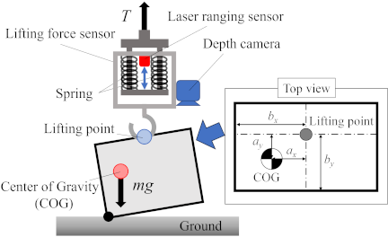
Fig. 2. Sensor arrangement for COG detection.
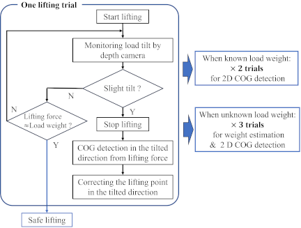
Fig. 3. Process flow of COG detection.
A depth camera was used to detect the direction of load tilt, indicating the direction of the COG. It detected changes in the depth image of the top surface of the load. When a slight tilting was observed, lifting could be halted based on this information, and the variation in the depth image revealed the tilting angle and direction. The force sensor detected the horizontal distance to the COG. This could be determined from the statics of the lifting force when any edge of the load bottom is slightly lifted. As the statics changed before and after this state, the increase in the lifting force also changed. Therefore, the COG could be estimated before the load was completely off the ground.
However, the horizontal two-dimensional position of the COG cannot be determined from a single lift, because the load usually tilts toward one of the four edges of the rectangular base. Therefore, two lifting trials were required when the weight of the load was known, and three trials were required when it was unknown. If the load is lifted just above the COG, it leaves the ground simultaneously without tilting. In this case, detecting the COG from the initial slight tilt of the load was not feasible, indicating that the lifting position was correct. Therefore, the proposed device can monitor the safe lifting of loads.
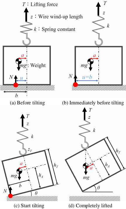
Fig. 4. Statics during the process of lifting a load.
2.2. Statics of Lifting a Load
To demonstrate that the moment when a slight load tilt begins can be used to determine the distance to the COG, we analyzed the statics of the lifting process. Fig. 4 shows the lifting process until the load is fully raised, which can be classified into states (a)–(d) as the crane wire is wound up. This lifting model was simplified based on the following considerations.
-
Multiple wires are commonly used for lifting as shown in Fig. 1; however, the load is lifted at a single point on the hook. The tension in the multiple wires is merely an internal force, and it becomes a single resulting force vector at the hook point.
-
The crane wire is vertical because the hook is lowered and hooked onto the load. In general crane operations, particularly when lifting a large load where the COG is a concern, the wire height reaches tens of meters. Unless the load is extremely tall relative to the base, even if the load tilts slightly and the hook position shifts by several dozen centimeters, the inclination of the wire is slight and can be ignored.
-
Considering the frictional force at the contact point with the ground, it is statically balanced with the horizontal component of the lifting force vector. When the wire is almost vertical, the frictional force is small compared to the lifting force and can be neglected in the statics of the COG detection.
The crane wire is assumed to be lifted at a constant speed \(v\). The wind-up length of the crane wire is denoted by \(z\) and is expressed as follows:
Let the weight of the load be \(mg\) (gravitational acceleration \(g\)), the constant of the built-in spring of the lifting force sensor be \(k\), and the normal force from the ground to the load be \(N\). If the load is on the ground, the normal force \(N\) balances the gravitational force, \(N=mg\).
Initially, the crane wire was wound, but the load remained neither tilted nor lifted (Fig. 4(a)). The lifting force \(T\) was obtained as follows:
When the normal force shifts to the edge of the base of the load (\(u=b\)), the load begins to tilt, whereas the bottom edge remains in contact with the ground. This moment (Fig. 4(b)) is important for COG detection. Let the lifting force in this state be \(T_b\), and it can be expressed as
Subsequently, the load tilts gradually (Fig. 4(c)). As the lifting point rises, the lifting force \(T\) is expressed as follows:
Finally, the load is completely lifted (Fig. 4(d)). As the COG lies directly beneath the lifting point, the lifting force and tilt of the load remain constant and are expressed as follows:
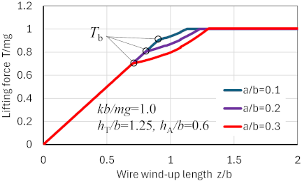
Fig. 5. Theoretical graph of lifting force.
A graphical representation of the above analysis is shown in Fig. 5. Each parameter is normalized by \(b\), which is a representative dimension. Fig. 5 indicates examples of the theoretical change in the lifting force with respect to the amount of wire wound. The point \(T_b\) at which the rate of increase in the lifting force changes depends on the misalignment between the COG and the lifting point. Therefore, when the lifting force \(T_b\) is found, the COG position \(a\) can be determined using Eq. \(\eqref{eq:ab}\), as described above. However, the direct detection of this point is challenging because of the noise in the lifting force sensor signal. A piecewise linear regression is applied to the force data before and after the load begins to tilt. This method identifies the breakpoint that minimizes the approximation error by dividing the data into two segments and applying a linear regression. The lifting force \(T_b\) is expressed as the intersection point of the regression lines in the two segments, divided using this method.
2.3. Discussion of Detection Accuracy
The accuracy required to detect the COG is discussed in this section. If a misalignment exists between the COG and the lifting point, the lifting point is adjusted directly above the estimated COG before lifting again. If an error exists in the estimated COG, the completely lifted load is tilted by the error. This tilt is assumed to be allowed up to \(\theta = 0.1\) rad (\(\simeq 6°\)) for safety. Because the tilt angle is determined using Eq. \(\eqref{eq:liftup}\), the COG position \(a\) should be estimated with an accuracy of less than approximately 0.1 with respect to \((h_T - h_A)\). Although this is a rough approximation, assuming that the dimensions of \((h_T - h_A)\) and \(b\) are nearly equal, \(a/b\) should be less than 0.1. Specifically, \(a\) should be estimated with an accuracy of less than approximately 10% relative to \(b\). From Eq. \(\eqref{eq:ab}\), the accuracy of the COG position \(a\) and the lifting force \(T_b\) is proportional; therefore, \(T_b\) should be measured with an accuracy of less than 10% of the load weight \(mg\).
When the load weight \(mg\) is unknown, the estimation of \(mg\) is considered as follows. Let the error of \(m\) be \(\Delta m\), Eq. \(\eqref{eq:ab}\) then gives
2.4. Tilt Detection by Depth Camera
The method for detecting the tilt angle and direction from the depth image is described by analyzing the motion of the top surface of the load. A depth camera mounted on the crane hook continuously captures images until a slight tilt occurs. Because the approximate distance between the camera and the load top is known, depth data within a specified range near the load top are extracted, and changes from the initial depth data before lifting are recorded. These differences are independent of the load shape. The camera (depth image) may rotate slightly during lifting because the hook allows limited rotational movement relative to the load. Therefore, the depth images are corrected using this rotation angle before computing the differences. In addition, RGB images captured simultaneously are used to calculate the rotation angle between frames through feature point matching. After processing, the least-squares plane of the point cloud data in the difference depth image is obtained as shown in Fig. 6. The normal vector of this plane provides the tilt angle and direction of the load. The lifting can also be stopped based on the detected slight tilt angle.
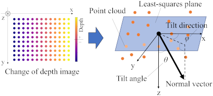
Fig. 6. Detection of tilt angle and direction by depth image.
2.5. COG Detection for Known Weight Load
The COG detection process for a load of a known weight is described herein. After the load tilts slightly and lifting is stopped by monitoring the tilt angle with a depth camera, the horizontal COG position, \(a\), is obtained from Eq. \(\eqref{eq:ab}\) using the lifting force \(T_b\), as mentioned previously.
Here, we aim to determine the tilt direction. Fig. 2 shows the lifting point and COG of the load from the top view. The load initially tilts toward the side with a larger eccentricity ratio \(a/b\) where \(a\) is the horizontal distance from the lifting point to the COG, and \(b\) is the horizontal distance from the lifting point to the load bottom edge, in the \(x\)- and \(y\)-directions. If \(a/b\) is equal in both directions, the load tilts toward the corner. However, this scenario is highly unlikely and is not addressed herein (it can be monitored using a depth camera). Tilting toward only one side implies that only one coordinate of the COG position is determined from a single lift, as shown in Fig. 7. After the lifting point is adjusted to the estimated COG position in the tilted direction, a second lift is performed. Subsequently, the eccentricity \(a/b\) in other directions persists, causing the load to tilt accordingly. Thus, the other coordinate of the COG position is determined.
For the load with a rectangular bottom, two lifting trials are required to determine the two-dimensional COG position and adjust the lifting point. Additionally, the tilted side of the rectangle must be identified using a depth camera.
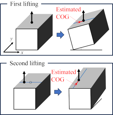
Fig. 7. COG detection procedure for known weight load.
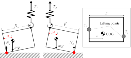
Fig. 8. COG detection for unknown load weight.
2.6. COG Detection for Unknown Weight Load
A method for detecting the COG when the load weight is unknown is explained in this section. In these cases, an appropriate lifting method must be developed. As shown in Fig. 8, both sides (directly above both ends of the bottom) of the load should be slightly lifted. The lifting position can be at any point on either side. Slight tilting is monitored using the depth camera, and the lifting forces \(T_1\) and \(T_2\) are measured at these times. When the load weight is \(mg\), and the horizontal position of the COG from the first lifting point is \(\alpha\), the balance of moments for two conditions is expressed by the following equation.
After adjusting the lifting point to just above the estimated COG position, the load is lifted again. This allows us to determine the other COG coordinate, as described previously. Generally, three lifting trials are required to determine the load weight and two-dimensional COG position when the weight is unknown.
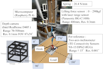
Fig. 9. Experimental setup.
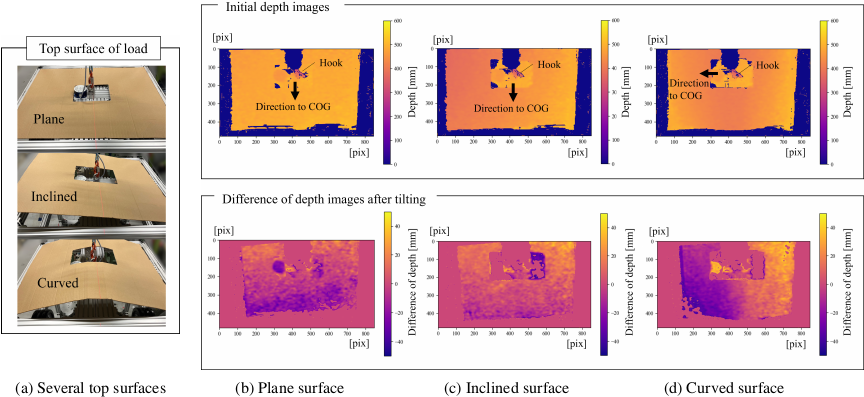
Fig. 10. Change of depth images from the initial condition.
3. Experiments
Several experiments were conducted to validate the proposed COG detection method. Fig. 9 shows the experimental setup. The prototype lifting force sensor had two compression coil springs, 40 mm in diameter and 250 mm in length, which contracted by 150 mm at a maximum force of approximately 300 kgf. The force sensor value was obtained by measuring spring deformation using a laser range sensor. The accuracy of this force sensor was approximately 2 kgf, which was less than 1% of the measurement range. A depth camera (1280 \(\times\) 720 pixels) was mounted approximately 400 mm above the hook to capture depth and RGB images of the top surface of the load. The depth accuracy was \(\pm\) 2% at 500 mm. This was sufficient to detect a slight tilt in the load because the tilt angle was averaged from the displacement of many point clouds. Furthermore, this information was used as a trigger to detect the COG and was not directly used for COG calculations based on the lifting force. The microcomputer controlled these sensors and wirelessly transmitted the data to the main PC. Data, including the depth images, were sampled at approximately 10 Hz.
A rectangular load (800 \(\times\) 700 \(\times\) 700 mm) was placed on a flat indoor floor and lifted at a speed of 5 mm/s. The load frame weighed 34.1 kg, with its weight and COG adjusted by adding disk-shaped weights (5.0 kg \(\times\) 8). Because the equations for COG detection are expressed in terms of dimensional ratios and force ratios, even if the load scale or weight differs from the real conditions, the mechanical properties for lifting remain unchanged. Regarding the contact between the load and floor, its roughness causes no significant problem because only the bottom edge of the load makes contact when the load tilts slightly for COG detection.
3.1. Detection of Load Tilting
First, experiments were conducted to detect the tilt angle and direction of the load from a point cloud obtained by differentiating the depth images from the initial condition. Depth data of \(\pm\)150 mm from the hook was used to detect the load tilting. The rectangular load (64.8 kg) was lifted several centimeters using the center of its top plane as the lifting point, but it remained partially in contact with the floor. As shown in Fig. 10, plane, inclined, and curved surfaces were prepared as the top surface of the load. The load was eccentrically applied in four directions (\(0°\), \(90°\), \(180°\), \(270°\)). Each condition was tested five times.
Figure 10 shows the initial depth images (upper panel) and the changes after tilting (lower panel). The direction of the COG from the lifting point is also shown in the figure. The initial image captures the shape of the top surface of the load. Subsequent changes in this image consistently reflect tilting toward the COG direction, regardless of the top-surface geometry. With a fixed camera, the height of one edge of the tilted load remained unchanged, resulting in a zero difference in the depth image near the edge. However, when the camera was mounted on the rising hook, the depth difference near the lifting point consistently remained zero.
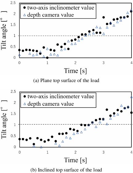
Fig. 11. Variations in tilt angle while lifting a load.
Figure 11 shows the variations in the tilt angle for the two cases as typical examples. For comparison, a two-axis inclinometer was attached to the load and its value was considered as the true tilt angle and direction. The tilt angle obtained from the change in the depth image increased linearly after starting to tilt and was close to the true value of the inclinometer. To clearly detect the beginning of the load tilt, it was sufficient to capture a tilt angle of approximately \(1°\).
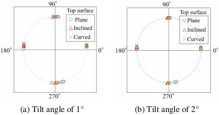
Fig. 12. Detected tilt direction for four eccentric conditions.
Figure 12 shows the tilt direction obtained from the change in the depth image when the tilt angles are 1° and 2°, as measured using a two-axis inclinometer. The true directions are indicated in Fig. 9. The error in the tilt direction was approximately the same when the tilt angle of the load was 1° or 2°, and the maximum error was approximately 15°. The tilt direction was used to determine in which of the four directions the rectangular-bottomed load tilted. A tilt angle of only 1° was sufficient to detect the tilt direction regardless of the top surface shape.
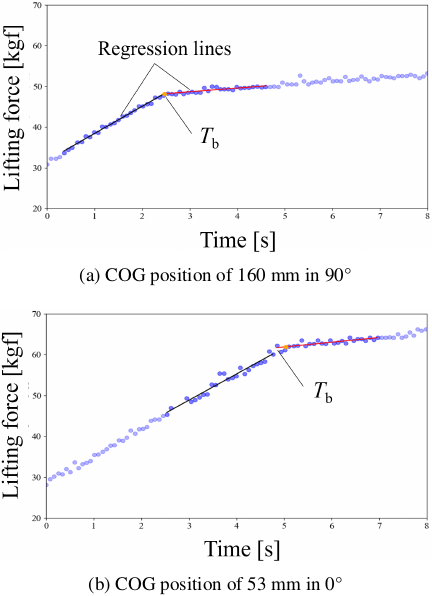
Fig. 13. Variations in lifting force while lifting a load.
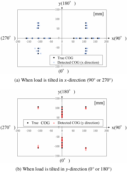
Fig. 14. Detected COG position.
3.2. Experiment for Known Weight Load
An experiment was conducted to detect the COG position of a load when its weight was known. The COG position was changed by replacing the weights at several positions in the main load frame. The load was lifted until the tilt angle reached \(1°\), as measured using a depth camera.
Figure 13 shows typical examples of the variations in the lifting force. An increase in the lifting force at the onset of the load tilt is clearly observable. The farther the COG is from the lifting point, the smaller the lifting force \(T_b\) at this point, which is related to the load weight. To determine the lifting force \(T_b\) accurately, piecewise linear regression was applied to 50 samples of force data from the time when the tilt angle reached \(1°\). Substituting this lifting force \(T_b\) into Eq. \(\eqref{eq:ab}\), we obtained the COG position in the direction in which the load is tilted.
The detection results at various COG positions are shown in Fig. 14. The experiment was conducted thrice at each of the 36 weight positions. Even if the COG position was offset two-dimensionally from the lifting point, only the position coordinates in the direction of the load tilt could be detected. Fig. 14(a) shows the results when the load is tilted in the \(x\)-direction and the \(x\)-coordinate of the COG is detected. The detected COG position is plotted in the \(x\)-direction near the corresponding true COG position. Fig. 14(b) shows the results in the \(y\)-direction. The maximum errors of the COG position \(a\) are 14.4 and 12.6 mm in the \(x\)- and \(y\)-directions, respectively. The horizontal distances from the lifting point to the bottom edge \(b\) are 400 and 300 mm in the \(x\)- and \(y\)-directions, respectively, and the maximum errors are less than 5% of \(b\). In addition, the error shows a slight dependence on the COG position, and the results are sufficiently accurate, as discussed in Subsection 2.3.
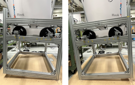
Fig. 15. Lifting both sides to measure lifting forces \(T_1\) and \(T_2\).
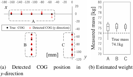
Fig. 16. Detection results of mass and COG for unknown weight load.
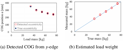
Fig. 17. Detection results for different load weights of COG group C.
3.3. Experiment for Unknown Weight Load
Experiments were conducted to detect the load weight before estimating the COG when the weight was unknown. In this case, both sides of the load are alternately lifted, as shown in Fig. 15. The lifting point was set at the midpoint of each side along the \(y\)-direction. The horizontal distance between two lifting points \(\beta\) was 700 mm. The load weight was 74.1 kg, with a replaceable weight of 40.0 kg. Lifting forces \(T_1\) and \(T_2\) were obtained when the tilt angle of the load was \(1°\). Each experiment was performed in triplicate.
Figure 16 shows the load weight and COG positions detected using Eq. \(\eqref{eq:unknown}\) with a changing weight position. The estimated load weight is shown for each group (A, B, and C) of the COG positions. The maximum error in load weight was 2.1 kg (2.8%). As lifting forces are applied on both sides along the \(y\)-direction, all detected COG positions lie in the \(y\)-direction and are plotted near the true COG positions. The maximum error in the COG position was 4.1 mm, which was less than 1% of the distance between the two lifting points \(\beta\). Compared to the case where the load weight is known, the accuracy is improved owing to the lifting from both sides, which are farther from the COG.
Figure 17 shows the detection results when the load weight was varied around COG group C. The COG position was expressed as the distance from the load edge in the \(y\)-direction, with the midpoint located at 350 mm. The maximum errors in the mass and COG position were 1.6 kg and 5.8 mm, respectively. Similar to the previous experiment, the load weight and COG position were detected with sufficient accuracy.
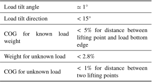
Table 1. Performance (detection accuracy) of prototype system obtained from experiments.
4. Conclusion
We proposed and developed a sensor system capable of detecting the COG of a load with a rectangular base “before” it is completely lifted, using lifting force measurements and depth images. The depth camera in the prototype system could detect a slight tilt angle of \(1°\) and determine the tilt direction based on changes in the depth image of the top surface of the load. According to the statics of lifting a load, the rate of increase in the lifting force changed when the load started to tilt, depending on the misalignment of the COG and lifting point. This enabled the detection of the COG position when the load weight was known. Piecewise linear regression was proven to be effective in determining this lifting force. Because an eccentric load typically tilts toward one direction of the four edges of the base, two lifting trials are required to determine the COG in a two-dimensional plane when the load weight is known. Three trials are required if the weight is unknown. A specialized lifting method and corresponding calculations are presented to estimate both the load weight and the COG position. In both cases, as listed in Table 1, the experimental results demonstrate that the COG position can be estimated with sufficient accuracy to maintain a tilt angle below approximately \(6°\) (0.1 rad) when the load is completely lifted. Therefore, the proposed device significantly enhances the safety of both manually operated and automatic crane-lift systems.
- [1] W. He, Z. Lin, W. Li, C. J. Wong, D. Kong, and E. W. L. Loh, “The comprehensive safety assessment method for complex construction crane accidents based on scenario analysis – A case study of crane accidents,” Computers & Industrial Engineering, Vol.199, Article No.110716, 2025. https://doi.org/10.1016/j.cie.2024.110716
- [2] R. L. Neitzel, N. S. Seixas, and K. K. Ren, “A review of crane safety in the construction industry,” Applied Occupational and Environmental Hygiene, Vol.16, No.12, pp. 1106-1117, 2001. https://doi.org/10.1080/10473220127411
- [3] W. Jiang, L. Ding, and C. Zhou, “Digital twin: Stability analysis for tower crane hoisting safety with a scale model,” Automation in Construction, Vol.138, Article No.104257, 2022. https://doi.org/10.1016/j.autcon.2022.104257
- [4] Y. Wang, H. Suzuki, Y. Ohtake, T. Kosaka, and S. Noguchi, “Generating a visual map of the crane workspace using top-view cameras for assisting operation,” J. Robot. Mechatron., Vol.32, No.2, pp. 409-421, 2020. https://doi.org/10.20965/jrm.2020.p0409
- [5] Z. Zhou, B. Johns, Y. Fang, Y. Bai, and E. Abdi, “Physics-informed neural network for load sway prediction in travelling autonomous mobile cranes,” Advanced Engineering Informatics, Vol.65, Article No.103269, 2025. https://doi.org/10.1016/j.aei.2025.103269
- [6] L. C. Price, J. Chen, J. Park, and Y. K. Cho, “Multisensor-driven real-time crane monitoring system for blind lift operations: Lessons learned from a case study,” Automation in Construction, Vol.124, Article No.103552, 2021. https://doi.org/10.1016/j.autcon.2021.103552
- [7] A. Zhu, Z. Ahang, and W. Pan, “Technologies, levels and directions of crane-lift automation in construction,” Automation in Construction, Vol.153, Article No.104960, 2023. https://doi.org/10.1016/j.autcon.2023.104960
- [8] T. Tanizaki, K. Yamada, S. Nakagawa, and H. Katagiri, “Scheduling algorithm using path relinking for production process with crane interference,” Int. J. Automation Technol., Vol.17, No.1, pp. 71-80, 2023. https://doi.org/10.20965/ijat.2023.p0071
- [9] J. Sasaki, G. Nishida, A. Yamashita, Y. Aiyama, J. Ota, and T. Arai, “Estimating the center of gravity of an object using tilting by multiple mobile robots,” Proc. 1997 IEEE/RSJ Int. Conf. on Intelligent Robot and Systems, Vol.3, pp. 1748-1753, 1997. https://doi.org/10.1109/IROS.1997.656597
- [10] Y. Watanabe, “Center of gravity detection system,” Patent, WO 2013/061989 A1, 2013.
- [11] X. T. Pham, M. Okuma, M. Bur, and Z. Abidin, “Vehicle’s center of gravity estimation using pavement Weight-in-Motion,” Mechanical Engineering J., Vol.9, No.1, Article No.21-00322, 2022. https://doi.org/10.1299/mej.21-00322
- [12] X. Huang and J. Wang, “Center of gravity height real-time estimation for lightweight vehicles using tire instant effective radius,” Control Engineering Practice, Vol.21, No.4, pp. 370-380, 2013. https://doi.org/10.1016/j.conengprac.2012.12.003
- [13] C. Lin, X. Gong, R. Xiong, and X. Cheng, “A novel H _infty ∞ and EKF joint estimation method for determining the center of gravity position of electric vehicles,” Applied Energy, Vol.194, pp. 609-616, 2017. https://doi.org/10.1016/j.apenergy.2016.05.040
- [14] S. T. Germann and R. Isermann, “Determination of the centre of gravity height of a vehicle with parameter estimation,” IFAC Proc. Volumes, Vol.27, No.8, pp. 563-568, 1994. https://doi.org/10.1016/S1474-6670(17)47768-8
- [15] M. H. Zaheer and P. Yoon, “Estimation of mobile robot’s center of gravity for rollover detection,” Proc. 2020 IEEE/ASME Int. Conf. on Advanced Intelligent Mechatronics, pp. 1567-1572, 2020. https://doi.org/10.1109/AIM43001.2020.9159030
- [16] Y. Yu, K. Fukuda, and S. Tsujio, “Estimation of mass and center of gravity of graspless unknown object using gravity equi-effect planes,” Proc. 1998 IEEE/RSJ Int. Conf. on Intelligent Robots and Systems, Vol.3, pp. 1497-1502, 1998. https://doi.org/10.1109/IROS.1998.724807
- [17] M. Hatano, “Estimation of center of gravity for withdrawal works of unknown indefinite shape rubbles for rescue robots,” Proc. 2017 IEEE Int. Conf. on Mechatronics and Automation, pp. 1970-1975, 2017. https://doi.org/10.1109/ICMA.2017.8016120
This article is published under a Creative Commons Attribution-NoDerivatives 4.0 Internationa License.