
Paper:
Electropermanent Magnet Modular Boa (EMB): Reconfigurable Snake Robot with Magnetic Wall Interaction

Snake robots possess high mobility by leveraging their redundant degrees of freedom. However, it is challenging to optimize the degrees of freedom of conventional snake robots with fixed configurations for unknown environments and it is particularly difficult to maintain their operation by detaching failed joints. To enhance the environmental adaptability and fault tolerance of snake robots, in this study, we developed a modular snake robot capable of reconfiguring its degrees of freedom according to the situation. In our previous systems, even though the mechanical coupling mechanisms achieved robust connections, the systems were structurally complex at their interfaces. In contrast, even though magnetic coupling mechanisms resulted in simpler designs, the systems were susceptible to strong vibrations and shear loads during locomotion, which made it challenging to maintain stable electrical connections. To address these challenges, we developed the electropermanent magnet modular boa (EMB) in this study, which was a modular snake robot featuring hybrid connectors that balanced strong attraction forces via electropermanent magnet with mechanical support for shear loads through passive reinforcement pins. By ensuring the precise alignment of the reinforcement pins as positioning guides, we achieved simultaneous robust inter module coupling and electrical connectivity within a lightweight and simple structure. Furthermore, a unique feature of our hybrid connector is its dual functionality, where it can also be adapted for attachment to ferromagnetic surfaces, enabling both locomotion on ferromagnetic surfaces and module coupling with a single mechanism. We demonstrated the effectiveness of the physical EMB prototype based on characteristic evaluation of the standalone connector and locomotion experiments.
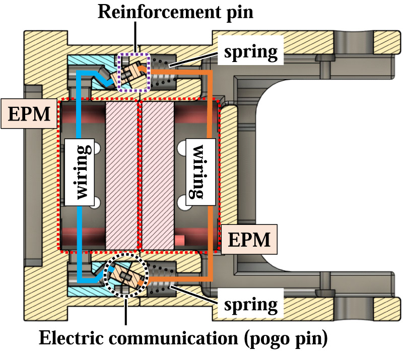
Details of the passive rod-lock mechanism and electrical contacts
1. Introduction
Snake robots possess redundant degrees of freedom through the serial connection of numerous joints, enabling a diverse range of locomotion modes suitable for confined spaces and rough terrains 1,2. To date, a variety of three-dimensional mobility capabilities have been demonstrated, including gait designs mimicking biological snakes 3 and robots intended for specific tasks such as stair climbing 4,5, ladder climbing 6, and locomotion within pipes 7,8,9.
Conventional snake robots typically feature a structure in which pitch and yaw joints are connected alternately in series. However, in complex real-world environments, it is difficult to determine the optimal configuration of an entire robot in advance. For instance, although a longer body length is advantageous for surmounting high steps, an excessively long body can hinder maneuverability in confined spaces. Therefore, a system capable of dynamically adjusting the body length of the robot through separation and reconnection during operation provides a new paradigm for enhancing the adaptability of snake robots in unknown environments 10,11.
Furthermore, the ability to separate and reconnect significantly contributes to the enhancement of fault tolerance. Even though scholars have conducted research on fault tolerance and have proposed methods where functional joints compensatorily support failed joints, these methods often suffer from increased mechanical or computational burden on the remaining functional joints 12. In contrast, a method that physically detaches failed units and reconfigures the system using only functional modules is highly effective to ensure the overall survivability of the system.
We have previously proposed a concept for a modular snake robot with separation and reconfiguration capabilities and developed several functional prototypes 13,14. However, the connection mechanisms (connectors) still faced challenges, such as the inability to perform active engagement and disengagement, and insufficient physical connection strength.
Connectors designed to alter the degrees of freedom of configurations require high reliability to withstand the vigorous propulsive motions and environmental interactions inherent to snake robots. Diverse connectors have been proposed for modular robotics. Representative methods include those using mechanical latches or mating structures 15,16. Although these methods provide high coupling rigidity and secure retention, they tend to involve complex drive mechanisms and actuators, leading to increased weight and reduced maintainability. Conversely, magnetic connectors using permanent magnets 17,18,19 offer advantages in terms of simplicity and lightweight design by actively controlling the gap between the magnet and objects that can be attracted by magnets, such as ferromagnetic objects. Nevertheless, because snake robots propel themselves by grounding their entire bodies, the connections are subjected to large external forces and vibrations from all directions, and not only from the attraction direction. Conventional magnetic attraction methods provide superior holding force. However, they are susceptible to shear loads across the attraction interface, which can cause misalignment or detachment during vigorous locomotion.
Considering the practical application of snake robots, it is essential to harmonize a “simple structure” for maintainability and weight reduction with “robust coupling” that can resist external interference.
To address these challenges, we proposed a hybrid connector that combined an electropermanent magnet (EPM), which can switch its magnetic attraction state by a short current pulse and maintain the attached state without continuous power supply using passive reinforcement pins. We also developed a new modular snake robot called the electropermanent magnet modular boa (EMB). This design achieved robust coupling capable of withstanding loads during locomotion while maintaining a simple structure that did not require additional actuators for mechanical locking. Although the introduction of reinforcement pins required precise alignment during coupling, these pins also served as positioning guides for electrical contacts, thereby contributing to stable electrical connections. Furthermore, the proposed connector can be used as an attachment mechanism for ferromagnetic surfaces, fulfilling the dual requirements of inter module connection and ferromagnetic-surface attachment within a single integrated mechanism. Since snake robots generate locomotion through whole-body contact with the environment, their ability to actively attach to ferromagnetic surfaces can extend their locomotion capability to steel environments. Therefore, the proposed connector enables reconfiguration and expands the range of environments in which modular snake robots can locomote.
The remainder of this paper is organized as follows. Section 2 provides an overview of the EMB robot design. Section 3 describes the mechanical structure and performance characterization of the proposed hybrid connector. Section 4 presents the effectiveness of the proposed system through experimental evaluations of the attachment and connection/disconnection tasks on steel surfaces using the EMB prototype. Finally, Section 5 presents conclusions of this study and recommendations for future work.
2. Design of the EMB Module
This section presents an overview of the design of the individual modules constituting the EMB. The fundamental locomotion capabilities of a single module (i.e., achieving translational and rotational motion within a plane) and the basic configuration for extending these modules into a snake form have been investigated in our previous studies 13,14, whereas in this study, we provide comprehensive details of the design principles, dimensional configurations, mechanical structures, and electrical architectures specific to the EMB.
2.1. Basic Configuration and Design Principles
The EMB was configured as a modular snake robot capable of morphological reconfiguration by separation and connection of the individual modules. Because the modules were expected to be temporarily isolated during the reconfiguration process, a key design requirement for the EMB was that “even in a separated state, a single module must be capable of independent translational and rotational motion to facilitate reconnection.”
Figure 1 illustrates the overview and arrangement of the links and joints of a single module. To achieve the minimum configuration required for independent planar motion, the module was designed with five links and four joints with connection interfaces integrated at both ends of the EMB.
For planar locomotion, a three-link, two-joint snake robot represents the minimum configuration capable of generating propulsion by applying phase-shifted traveling wave commands to its joints. In this study, this concept was extended to three-dimensional locomotion by adopting a five-link, four-joint module configuration that allowed phase-shifted joint motions to be generated independently in the pitch and yaw directions.
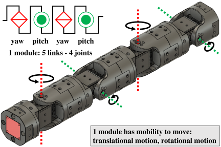
Fig. 1. Overview of an EMB module composed of five links and four joints.
2.2. Mechanical Structure
Figure 2 shows the mechanical design of a single module. The EMB module had a total length of 555 mm, an outer diameter of 80 mm, and a weight of approximately 1.5 kg. The length of each central link was set to 138.75 mm, whereas the lengths of the connector-mounted links at both ends were 79.75 mm and 59 mm, respectively, in terms of the design dimensions. This dimensional configuration ensured that when multiple modules were connected in series (Fig. 3), the effective link length, including the connection interface, aligned with those of the central links.
Each link featured a hollow structure to accommodate internal wiring and control boards. By routing the motor cables through the axes of rotation, we minimized the risk of wire breakage and interference between the wiring and surrounding structures. The connection mechanisms for inter-module coupling and attachment to ferromagnetic surfaces were located at both ends of the module. For the connectors, we developed hybrid connectors that combined an EPM with a passive mechanical lock. Detailed descriptions of the connector structure and operating principles are provided in Section 3, and the experimental evaluations are presented in Section 4.
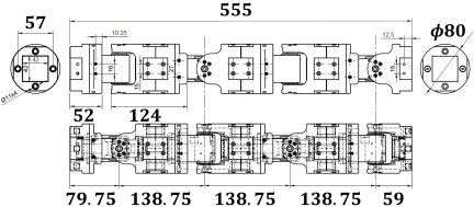
Fig. 2. Mechanical design of an EMB module.
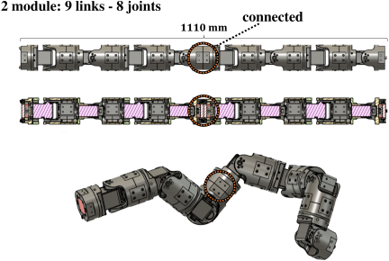
Fig. 3. EMB consisting of two modules connected in series.
2.3. Electrical Configuration
The electrical architecture of an EMB module is illustrated in Fig. 4. Smart servos (DYNAMIXEL XM540-W270-R, ROBOTIS Co., Ltd.) were used for the joint actuators.
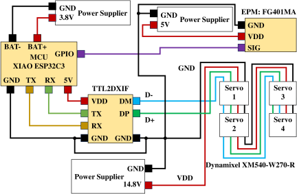
Fig. 4. Electrical configuration of a single module.
As the control system in the electrical architecture, a single embedded microcontroller (XIAO ESP32-C3, Seeed Technology Co., Ltd.) was mounted on each module to manage the joint control and on/off switching of the EPMs independently. Communication with DYNAMIXEL actuators was established via RS-485 half-duplex communication. To create an interface between the microcontroller and the actuators, a TTL-to-RS485 conversion board (TTL2DXIF) was integrated into the system for signal-level translation.
At this stage, the power system was designed for an external power supply, with independent power buses for the joint actuators and EPM drive system. The EPM allowed active switching between the magnetized (on) and demagnetized (off) states, thereby facilitating the engagement and disengagement of the modules.
3. Design of the Hybrid Connector
This section describes the design of the hybrid connector, which provides inter module coupling and attachment to the ferromagnetic surfaces for the EMB. First, we elaborated in detail the design concept, mechanical structure, and operating principle of the connector. Subsequently, we empirically measured the normal attraction force and in-plane frictional force of the connector. Based on these results, we evaluated the conditions for maintaining attachment on a ferromagnetic plane by analyzing two distinct failure modes: (1) peeling (detachment in the normal direction) and (2) sliding (sliding in the shear direction).
3.1. Design Principle of the Hybrid Connector
The connector of a modular snake robot must satisfy requirements that differ from those of general modular robots. Because a snake robot generates propulsion through whole-body contact with the environment, the connection interfaces between the modules are subjected to tensile loads in the attachment direction as well as to shear loads, bending moments, torsional disturbances, and vibrations during locomotion. In addition, a reconfigurable snake robot requires active engagement and disengagement, low power retention, and electrical coupling for the power supply and signal transmission between the modules.
Based on these requirements, we designed the hybrid integrating three functions within a single mechanism: (1) magnetic attachment using an EPM, (2) mechanical load support using passive reinforcement pins, and (3) electrical coupling using pogo-pin contacts. The EPM enabled active switching between attachment and detachment while maintaining the attached state without continuous power supply. The reinforcement pins mechanically supported shear loads and bending moments that could not be sufficiently resisted by magnetic attraction alone. The pogo-pin contacts established electrical connections when the two modules were coupled.
Furthermore, the hybrid connector served not only as an inter module coupling mechanism as well as an attachment interface to ferromagnetic surfaces. This dual functionality is important for modular snake robots because it allows the connector to contribute not only to reconfiguration, but also to locomotion on ferromagnetic surfaces.
3.2. Configuration and Operating Principle of the Hybrid Connector
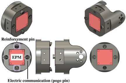
Fig. 5. Configuration of the proposed hybrid connector based on EPM.
Figure 5 shows the configuration of the proposed hybrid connector. This connector was designed to fulfill two distinct functions within a single integrated mechanism: (A) inter module coupling for reconfiguration, and (B) attachment to ferromagnetic walls for locomotion and manipulation tasks. To achieve this, we employed an EPM for attachment (retention in the normal direction) and a passive mechanical locking mechanism for load bearing (resistance against shear and bending forces).
The EPM consisted of an AlNiCo magnet and Nd magnet placed side-by-side, with a coil wound around them. By applying a short current pulse to the coil, the magnetization direction of the AlNiCo magnet, which had a relatively low coercivity, could be reversed. When the magnetization directions of the AlNiCo and Nd magnets were aligned, the magnetic flux was directed outside the EPM, and the EPM generated an attraction force. In contrast, when their magnetization directions were opposite, the external magnetic flux was largely canceled, and the attraction force was significantly reduced. With this principle, power was required only during the reversal operation, enabling low power retention unlike mechanisms that required continuous power supply.
In this study, the EPM (FG401MA, Zubax Robotics OÜ) was selected because it offered a favorable balance between weight and attraction force. This specific model weighed only 72 g and yet it provided a maximum attraction force of 250 N. The switching process took approximately 3 s and consumed about 5 W (5 V, 1 A). However, once the EMP was switched, the magnetic attraction was maintained even after the power was turned off, eliminating the need for continuous power to sustain the connection.
Figure 6 shows the details of the internal structure of the hybrid connector during engagement. The connector featured two reinforcement pins that mated with the corresponding holes of another module. When two modules were connected, a total of four reinforcement pins (two from each connector interface) supported the shear and bending loads. In addition, pogo pins were integrated into this passive mechanical locking mechanism to establish electrical connections for power and signals upon coupling. In contrast, during attachment to a ferromagnetic wall, the reinforcement pins and electrode components were retracted by springs (spring constant: 0.421 N/mm, maximum working load: 2.13 N), ensuring a smooth contact surface that did not interfere with the wall.
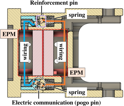
Fig. 6. Details of the passive rod-lock mechanism and electrical contacts.
4. Verification of the EMB Module
This section presents the evaluation of the proposed EMB module and hybrid connector from four perspectives: (1) magnetic attachment to the ferromagnetic surfaces, (2) single-module locomotion on a ferromagnetic wall, (3) mechanical connection stability between modules during locomotion, and (4) electrical coupling stability between connected modules. The purpose of these evaluations was to verify the basic functions required for a reconfigurable snake robot that used the same connector for both inter module coupling and attachment to ferromagnetic surfaces.
First, we measured the normal attraction force and maximum in-plane frictional force of the connector. Based on these measured values, we evaluated the static holding conditions of a single EMB module on a ferromagnetic wall by considering the peeling and sliding modes. Second, we conducted single-module locomotion experiments on a ferromagnetic wall to verify whether the proposed connector could function as an attachment interface for extending the locomotion capability of the EMB to ferromagnetic surfaces. Third, we performed two-module sidewinding experiments to evaluate the effect of passive reinforcement pins on the connection stability under whole-body locomotion. Finally, we evaluated the electrical continuity of the connector under external loads and moments to verify the stability of the power and signal connections between the coupled modules.
4.1. Characterization of the Attraction Force and In-Plane Frictional Force
This section presents the experimental measurements of the maximum values of the normal attraction force of the connector \(F_{\mathrm{attr, max}}\) and the in-plane frictional force \(F_{\mathrm{fric}}\) on the attraction surface. Here, \(F_{\mathrm{fric, max}}\) is defined as the effective maximum resistance force obtained under specific conditions, including the magnetization state and surface properties. A ferromagnetic flat plate was used as the attraction target. Following the initial magnetic attachment, it is known that the attraction force of the EPM increases with repeated activation cycles. Therefore, in this experiment, the EPM activation process was performed three additional times at the same position to ensure a stable and maximized attraction force.
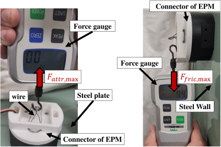
Fig. 7. Experimental setup used to measure the attraction force \(F_{\mathrm{attr,max}}\) and friction force \(F_{\mathrm{fric,max}}\) of the EPM.
Figure 7 shows the experimental setup used to measure the attraction force \(F_{\mathrm{attr, max}}\) and friction force \(F_{\mathrm{fric,max}}\) of the connector. To measure the normal attraction force, a tensile load was gradually applied in the direction normal to the wall while the EPM was attached to a ferromagnetic flat plate, with, a thickness of 7 mm. The maximum force was measured at the moment of detachment. This force is defined as \(F_{\mathrm{attr,max}}\). To measure the in-plane frictional force, a tensile load was applied vertically downwards with the EPM attached to the plate. The maximum load immediately before the onset of sliding was recorded as \(F_{\mathrm{fric,max}}\). Each measurement was performed 10 times to ensure statistical reliability.
Figure 8 shows the measurement results for the attraction force \(F_{\mathrm{attr, max}}\) and friction force \(F_{\mathrm{fric, max}}\). The experimental mean values were \(F_{\mathrm{attr,max}} = 122.25~\rm{N}\) and \(F_{\mathrm{fric,max}} = 71.29~\rm{N}\). In subsequent experiments, we employed these values as the empirical parameters representing the contact conditions assumed in this study to evaluate the attachment stability.
Here, we examined whether the reaction force from the springs could be neglected during wall attachment. When the connector was attached to a ferromagnetic wall, two springs (at the most) could interfere with the wall through the reinforcement pins. Because the maximum working load of each spring was 2.13 N, the maximum force acting in the direction opposite to the attachment surface due to the springs was 4.26 N. In contrast, the measured attraction force of the EPM to the ferromagnetic plane was 122.25 N. Therefore, the maximum spring reaction force corresponded to approximately 3.5% of the connector attraction force. Because this value was sufficiently small compared with the connector attraction force, the effect of the spring reaction force was neglected in the holding-condition analysis.
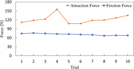
Fig. 8. Results of the measured attraction and friction forces.
4.2. Analysis of Holding Conditions on Ferromagnetic Walls
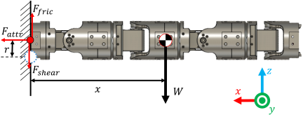
Fig. 9. Appearance of the EMB connected normal to the ferromagnetic wall.
To evaluate the feasibility of the EMB locomotion while being attached to a ferromagnetic wall, the EMB module must possess sufficient holding force to withstand its own weight. In this section, by referring to mechanical models of magnetic climbing robots 20,21, we defined the necessary conditions for maintaining the magnetic attachment by considering two distinct failure modes: peeling and sliding. Fig. 9 illustrates the cantilever state, which represents the most critical condition for an EMB module attached to a ferromagnetic wall. \(W\), \(x\), and \(r\) denote the weight of the EMB module, distance from the center of gravity to the edge of the attachment surface, and distance from the center of the connector to its edge, respectively.
In the peeling mode, the detachment process was approximated as a rigid-body rotation centered at the edge of the attachment surface, as indicated by the dashed circle in Fig. 9. The necessary condition to prevent peeling is given by the following inequality:
Since the mass of a single EMB module was \(M = 1.5~\rm{kg}\), its corresponding weight was \(W = Mg = 14.71~\rm{N}\). Based on the design specifications and the pre-calculated center of gravity, the distance from the center of the attraction surface to the center of gravity was \(x = 0.239~\rm{m}\), and the distance from the center of the connector to its edge was \(r = 0.040~\rm{m}\). Based on these parameters, the right side of Eq. (1) can be calculated as
Since the measured value \(F_{\mathrm{attr,max}} = 122.25~\rm{N}\) exceeded the calculated threshold, the designed single module was analytically capable of maintaining its magnetic attachment to the wall.
Next, the sliding mode for the static attachment state is discussed, as shown in Fig. 9. In Fig. 9, the \(z\)-axis is defined along the vertical direction of the wall surface. For the single-module cantilever configuration, the forces acting on the module in the \(z\)-direction were its own weight \(W\) and the frictional force \(F_{\mathrm{fric}}\) exerted by the attraction surface on the module. When the module remained stationary without sliding, these two forces were balanced in the \(z\)-direction. Therefore, assuming static equilibrium and neglecting the inertial and disturbance forces, the force balance in the \(z\)-direction is expressed as
Based on the action–reaction relationship, the EMB module applied a tangential force to the attraction surface with the same magnitude as the frictional force. In this study, the reaction force is denoted as \(F_{\mathrm{shear}}\). Thus,
Sliding occurred when \(F_{\mathrm{shear}}\) exceeded the maximum in-plane frictional force at the attraction surface. Therefore, the necessary condition to prevent sliding is given by
4.3. Locomotion Experiments on a Ferromagnetic Wall
The purpose of this experiment was to verify whether we could successfully achieve single EMB module locomotion on a ferromagnetic wall using a physical prototype, as predicted by the static analysis. The experimental setup consisted of vertical and horizontal ferromagnetic surfaces at the top and bottom. To ensure repeatability of the results, the EMB module was programmed to execute a predefined joint angle sequence for climbing up and down the shelf levels. The robot moved approximately 40 cm in the vertical direction. The timing of the connector connection and the disconnection was manually triggered by an operator via button inputs. These operations were restricted to specific steps within the sequence. In this experiment, 10 trials of ascending and descending locomotion were performed to confirm the reliability of the system’s performance on the ferromagnetic wall.
4.3.1. Wall-Descending Experiment
Figure 10 shows the sequence of descending locomotion on a ferromagnetic wall using the EMB module. This figure shows the transition states from (a) to (g). In step (c), the EPM on the joint 1 side was activated (on), and the establishment of a magnetic attachment to the ferromagnetic surface was confirmed. Successful attachment was determined by visual inspection of the contact interface (ensuring zero gap) and by verifying that no significant sliding or peeling occurred during subsequent movements. Next, the EPM on the joint 4 side was deactivated (off) to detach it and the robot’s posture was updated using the joint 1 side as the support point. In step (f), the reverse operation was performed: the EPM on the joint 4 side was activated to establish the attachment. After confirming the attachment, three additional activation cycles were executed to ensure maximum force, followed by deactivation of the EPM on the joint 1 side. Step (g) shows the final posture. This sequence of operations was repeated 10 times to evaluate the success rate. The joint states recorded during these movements are shown in Fig. 11. The gray vertical bars in Fig. 11 indicate the time spent in the robot state corresponding to each step in Fig. 10. The upper and lower plots show the joint angles and motor current values, respectively. For postures in which the robot supported its own weight in a cantilever configuration, particularly in step (e), we observed a significant increase in current in the base motor. Furthermore, when we observed a relatively high and constant current in a state without a cantilever, such as in step (c), where the joint angles remained fixed, we obtained a constrained state in which both end connectors were attached to the ferromagnetic surface. The stabilization of the motor current at a constant level was a distinctive feature of this constrained condition.
The descending locomotion was successfully completed in nine out of 10 trials, confirming that the physical EMB prototype was capable of descending along a ferromagnetic wall. The robot took an average of 180 s to complete. A single failure occurred between steps (a) and (b) because of an oscillations at the support point on the joint 4 side. These oscillations disturbed the contact interface, leading to peeling and subsequent detachment. We believe that this can be mitigated significantly by reducing the joint angular velocities to minimize the overall inertia of the robot during the transition.
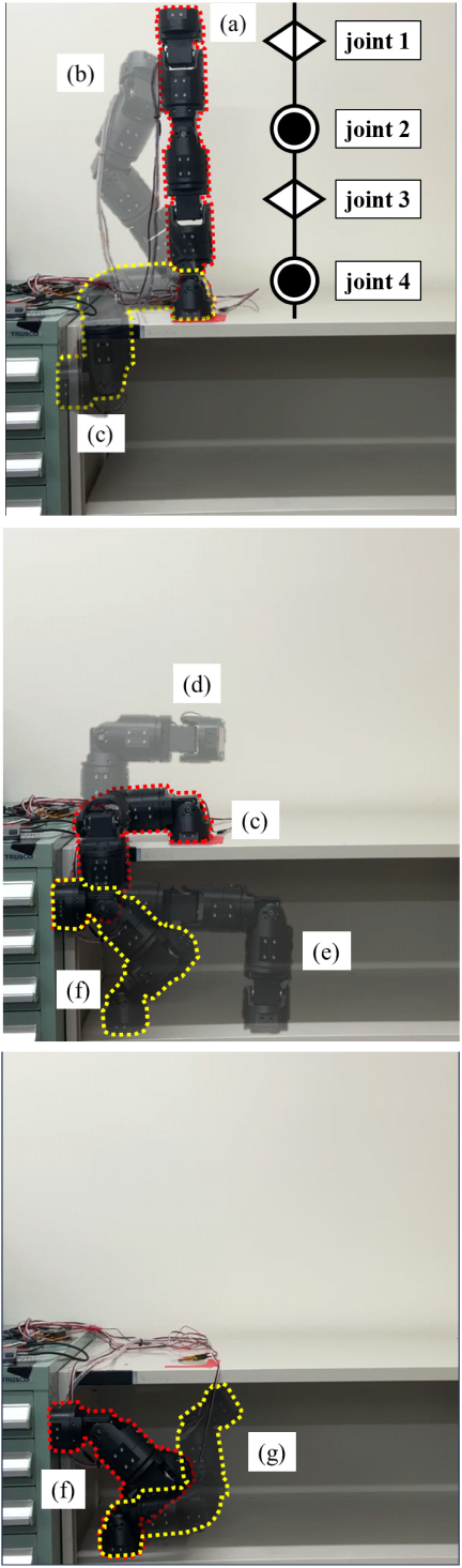
Fig. 10. Sequence of descending locomotion on a ferromagnetic wall using the EMB module.
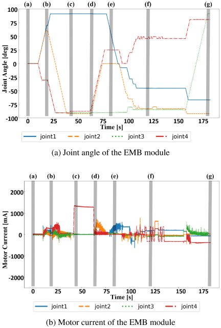
Fig. 11. Time histories of joint angle and motor current during a representative descending locomotion trial.
4.3.2. Wall Ascending Experiment
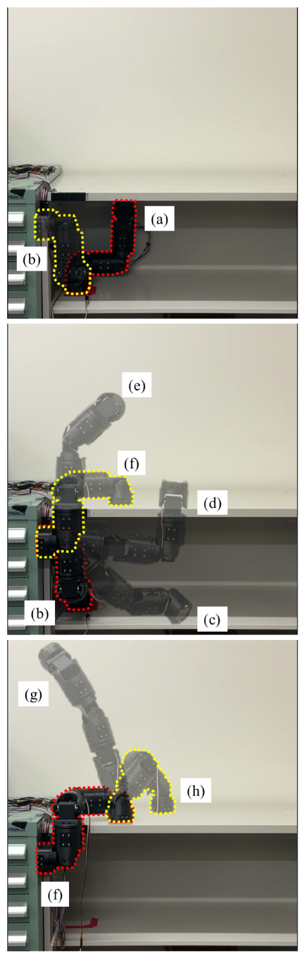
Fig. 12. Sequence of ascending locomotion on a ferromagnetic wall using the EMB module.
Figure 12 shows the sequence of the ascending experiment. This figure shows the transition states from (a) to (h). In step (b), the EPM on the joint 1 side was activated to establish a magnetic attachment. The fundamental procedure for engagement and disengagement was identical to that of the descending experiment. In step (f), the EPM on the joint 4 side was turned on for attachment, followed by turning off the EPM on the joint 1 side for detachment. Step (h) shows the final posture. This series of operations was repeated 10 times to evaluate the success rate. To mitigate the effects of inertia during ascent, the joint angular velocity was set to a lower value. Preliminary experiments showed a 0% success rate at 10°/s (the same speed used for descent), and therefore, the velocity was reduced to 3°/s to sufficiently minimize the overall inertia of the robot. The significantly higher failure rate during ascent compared with that during descent was attributed to the increased duration of movements acting against gravity. Fig. 13 shows the time histories of the joint angle and motor current. The gray vertical bars are defined in the same manner as those for Fig. 11. Similar to the descending experiment, the upper plot shows the joint angles whereas the lower plot shows the motor current values. We observed significant current peaks in the base motors during the postures in which the robot supported its own weight in a cantilever configuration, particularly in step (d) and during the transition between steps (f) and (g). Furthermore, as shown in step (f), when we observed a relatively high and constant current while the joint angles remained fixed in a non-cantilever state, we obtained a constrained condition in which both end connectors were attached to the ferromagnetic surface. The stabilization of the motor current at a constant level remained a distinctive characteristic of this constrained state.
The ascending locomotion was successfully achieved in all 10 trials. The robot took an average of 510 s to complete. However, preliminary experiments revealed that the attachment tended to become unstable when a rotational moment (torsional external force) was applied around the center of the attraction surface of the EPM. In general, this is a common characteristic of magnetic attachment mechanisms. To address this issue, we specifically designed the motion sequences and posture transition paths in this experiment to prevent excessive rotational moments at the attachment points. These results confirmed that, with appropriate motion planning, ascending locomotion on a ferromagnetic wall can be fully achieved using the physical EMB prototype.
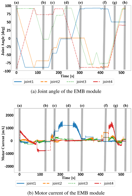
Fig. 13. Time histories of joint angle and motor current during a representative ascending locomotion trial.
4.4. Locomotion Experiments with Two Connected Modules
Although EPMs enable attachments with low power consumption, they are vulnerable to shear loads because of their reliance on friction. When operating a snake robot with multiple modules, we were concerned that the shear forces and bending moments acting on the interfaces could compromise the connection. To address this issue, we introduced a passive mechanical locking mechanism, resulting in a hybrid connector that combined the EPM attraction with mechanical support. The effectiveness of this mechanism in the connected state was verified using the EMB prototype.
The connection stability of the EMB prototype was evaluated under two conditions: (1) with and (2) without the passive mechanical locking mechanism. The robot executed sidewinding, a common gait for snake robots, for a duration of 20 s. The gait parameters for this experiment were experimentally tuned through preliminary trials, such that the connection would fail (i.e., detach) in the absence of the mechanical locking mechanism.
The sidewinding gait used in the experiment was implemented based on the following model. Each joint angle \(\theta_i(t)\) at time \(t\) for \(i\) is defined by the following equations. For the yaw joints, the joint angle is given by
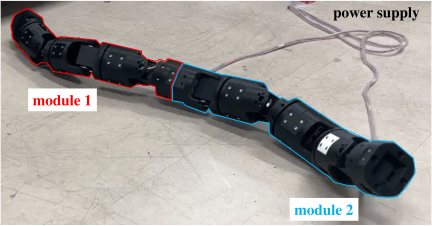
Fig. 14. Overview of the sidewinding locomotion experiment with two connected modules, conducted under conditions with and without the support parts.
4.4.1. Case Without Passive Mechanical Locking Mechanism
After establishing sufficient attachment with the EPMs, the sidewinding gait was initiated from a neutral straight posture (all joint angles at 0°). The robot was stopped after 20 s to inspect the status of the connection. This procedure was repeated 10 times.
The results are summarized in Table 1. The variable time [s] represents the duration for which the connection was maintained before failure occurred. This value indicated the lower bound of the connection integrity, as determined by the operator’s visual inspection.
| Trial | 1 | 2 | 3 | 4 | 5 | 6 | 7 | 8 | 9 | 10 |
| Results | F | F | F | F | F | F | F | S | F | F |
| Time [s] | 8 | 16 | 11 | 3 | 3 | 5 | 3 | – | 3 | 2 |
In trials 1–3, the connection was temporarily maintained, allowing the gait to proceed briefly. However, in most trials, the connectors detached during the initial phase of the transition from the neutral straight posture to the gait posture. This was attributed to the inability of the interface to withstand the sharp shear forces generated during the rapid shape transition. Although reducing the joint angular velocities to smoothen the transition might improve the motion time, the present configuration remained unreliable without mechanical reinforcement. Notably, in trial 8, the connection was successfully maintained for the full duration of 20 s duration, without significant misalignment observed at the connector interface.
4.4.2. Case with Passive Mechanical Locking Mechanism
The experiment was conducted by following the same procedure as that for the case without passive mechanical locking mechanism. The results are summarized in Table 2.
| Trial | 1 | 2 | 3 | 4 | 5 | 6 | 7 | 8 | 9 | 10 |
| Results | S | S | S | S | S | F | S | S | S | S |
With the passive mechanical locking mechanism, the connection was successfully maintained for the full duration of 20 s in nine out of 10 trials. These results indicated that the mechanical locking mechanism was highly effective in supporting shear loads at the connection interface. In the single failed trial, the connector was observed to lift off and strike the floor during the motion, which likely applied an excessive impulsive load to the joint, leading to failure.
4.5. Verification of Electrical Coupling
This section presents an evaluation of the electrical coupling capability of the proposed EPM-based hybrid connector. In the proposed hybrid connector, mechanical coupling and electrical connection for power supply and signal transmission must be established between the modules. To achieve this, pogo-pin contacts were integrated into the reinforcement pins such that electrical continuity was established when the two modules were mechanically connected. The pin assignment of the pogo-pin contacts is shown in Fig. 15.
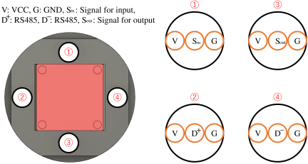
Fig. 15. Pin assignment of the pogo-pin contacts in the hybrid connector.
The purpose of this experiment was to verify whether an electrical connection could be maintained when external forces were applied to the connector. In the experiment, the test signals were supplied from one connector side and the corresponding output signals were received from the other connector side. Electrical continuity was maintained when there were no signal losses or distortions during loading.
4.5.1. Evaluation Under Translational Loads
First, we evaluated the electrical continuity under external loads applied along each coordinate axis. The experimental setup is shown in Fig. 16. After the two connectors were coupled, a load was applied using a force gauge and was maintained for 20 s. Because the connector had an approximately symmetric mechanical structure, representative loading tests were conducted along the three Cartesian axes.
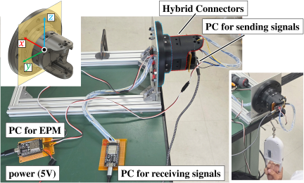
Fig. 16. Experimental setup used to evaluate the electrical continuity under external loads.
Preliminary experiments indicated that the mechanical connection using only the EPM without reinforcement pins failed when the applied load exceeded approximately 120 N. In contrast, the connector with reinforcement pins could withstand larger loads, although we observed structural failure when the load exceeded approximately 300 N. Based on these preliminary observations, the load level in this experiment was set to exceed 200 N but remained below the structural failure range.
The results are summarized in Table 3. When an average load of 231.3 N was applied in the \(x\)-direction, an electrical discontinuity occurred in one out of 10 trials. However, the mechanical connection was maintained even in this trial and the connector did not separate. When the average load in the \(x\)-direction was reduced to 180.4 N, the electrical continuity was maintained in all 10 trials. In the \(y\)- and \(z\)-directions, the electrical continuity was maintained in all 10 trials under an average load of 229.0 N and 226.3 N, respectively.
| Direction | Average load [N] | Continuity |
| \(x\) | 231.3 | 9/10 |
| \(x\) | 180.4 | 10/10 |
| \(y\) | 229.0 | 10/10 |
| \(z\) | 226.3 | 10/10 |
These results indicated that the electrical connection of the proposed hybrid connector was maintained under the tested conditions: approximately 180 N in the \(x\)-direction and more than 220 N in the \(y\)- and \(z\)-directions. On the other hand, the result obtained for the \(x\) direction under a load of 231.3 N suggests that the electrical contact stability is influenced by the loading direction and local contact state of the pogo pins.
4.5.2. Evaluation Under Moments Around Each Axis
Next, we evaluated the electrical continuity under the moments around each axis. The moments around the \(y\)- and \(z\)-axes were estimated from the translational load tests described in the previous section. Fig. 17 shows the force relationship during the load test in the \(z\)-direction. When an external force \(F_z\) was applied, reaction forces were generated at the reinforcement pins and contact surfaces. In this study, the moment around point A was used as a representative value to estimate the moment at which electrical continuity was maintained.
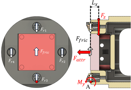
Fig. 17. Force relationship used to estimate the moment acting on the connector.
Let the distance from the loading point to the representative rotation center be \(L_x=12.5\times10^{-3}~\rm{m}\). Using the measured load in the \(z\)-direction, \(F_z=226.3~\rm{N}\), the moment around the \(y\)-axis was estimated as
The moment around the \(x\)-axis could not be directly estimated from the translational load tests. Therefore, a representative moment of 3.0 N m, which was comparable to \(M_y\) and \(M_z\), was experimentally applied to verify whether an electrical connection could be maintained. The experimental setup for applying the moment around the \(x\)-axis is shown in Fig. 18. The moment arm was set to \(L_y=8.0\times10^{-2}~\rm{m}\), and the applied load was \(F_{\mathrm{load}}=37.5~\rm{N}\). Thus, the applied moment was determined to be
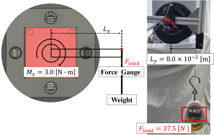
Fig. 18. Experimental setup for applying a moment around the \(x\)-axis.
Table 4 summarizes the evaluated moments. The results indicated that the electrical continuity was maintained under moments of approximately 3.0 N m around each axis under the tested conditions.
Although this experiment confirmed the electrical continuity under external loads and moments, a quantitative evaluation of the voltage drop and RS-485 communication quality remains a topic for future work.
| Moment | Value [N m] | Basis |
| \(M_x\) | 3.00 | Applied load test |
| \(M_y\) | 2.83 | Estimated from \(z\)-axis load |
| \(M_z\) | 2.86 | Estimated from \(y\)-axis load |
5. Conclusion
In this study, we developed an EMB prototype, which was a modular snake robot equipped with an EPM-based hybrid connector for inter module coupling and attachment to ferromagnetic surfaces. The proposed hybrid connector was developed by integrating an EPM, passive reinforcement pins, and pogo-pin electrical contacts, thereby enabling magnetic attachment with low-power retention, mechanical load support, and electrical connection within a single connector structure.
The experimental results confirmed the effectiveness of the proposed hybrid connector. Static holding analysis and wall locomotion experiments showed that a single EMB module could maintain attachment to and locomote on a ferromagnetic wall when an appropriate motion sequence was used. The two-module sidewinding experiments demonstrated that the passive reinforcement pins improved connection stability against shear loads and bending moments generated during whole-body locomotion. The electrical continuity tests also confirmed that the power and signal connections could be maintained under the tested external loads and moments, although the pogo-pin contact design still requires improvement under high directional loads.
Overall, the proposed hybrid connector was shown to be effective for realizing mechanical coupling, magnetic attachment, and electrical connection in a reconfigurable snake robot. In the future work, we intend to improve the robustness of the EMB module under practical surface conditions, such as surfaces with contamination, dust, and varying surface roughness, and we intend to further verify the connection and disconnection processes for autonomous docking, undocking, and multi-module reconfiguration.
Acknowledgments
This study was supported by OU-SPRING, and MEXT/JSPS KAKENHI Grant Number 26K07423.
This article is published under a Creative Commons Attribution-NoDerivatives 4.0 Internationa License.