
Paper:
Unit-Assembly Module Design Enabling Easy Disassembly and Automatic Assembly for Recyclable Robots
Xingyan Cheng, Shuangyu Wang, Junichiro Shiomi
 , and Yuki Asano
Department of Mechanical Engineering, Graduate School of Engineering, The University of Tokyo
7-3-1 Hongo, Bunkyo-ku, Tokyo 113-8656, Japan

This study proposes a unit-assembly architecture for robot modules that enables tool-less disassembly and automated assembly as a design pathway for recyclable robots. The robot module is decomposed into nine separable functional units (drivetrain, cooling, and control groups) connected exclusively via three types of releasable interfaces: magnetic docking, magnetic dowels, and mortise-and-tenon joints. This architecture allows non-destructive disassembly of all functional units in eight pull or slide operations, enables the clean separation of material streams, and facilitates the recovery and reuse of high-value components (motors, sensors, thermoelectric coolers, and printed circuit boards). Experimental validation confirms that the design does not compromise performance: the drivetrain achieves stable positioning (settling time ∼0.9 s, steady-state error ∼1%) and the active cooling system reduces motor temperature to room temperature within 200 s. Furthermore, we demonstrate an automatic assembly system using a 4-DOF robot arm with YOLOv8-based vision (mAP50=0.828), thereby validating that a representative set of releasable interfaces supporting disassembly are also compatible with the robotic assembly. Full nine-unit automatic assembly remains a topic for future investigation.
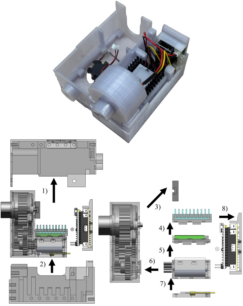
Unit-assembly design for robot recycling
1. Introduction
The global inventory of operational industrial robots reached approximately 4.3 million units in 2023 and continues to increase 1, thus rendering robotic hardware an emerging source of future electronic waste. Conventional robot modules integrate motors, gears, sensors, printed circuit boards (PCBs), and housings into dense multi-material assemblies optimized for performance and compactness 2,3. Their use of adhesives, potting compounds, and non-standard fasteners renders end-of-life (EoL) disassembly costly or destructive. This results in component shredding, which causes the loss of reusable high-value components 4,5.
Modular reconfigurable robotics has demonstrated the significance of releasable module-level connectors for system reconfiguration 6,7,8,9,10,11, whereas design for disassembly (DfD) provides principles for recoverable products 12,3,4. However, these approaches have not been jointly demonstrated for a self-contained robot actuator module whose internal units must remain functional, reusable, and compatible with automated assembly.
This study proposes a unit-assembly architecture that decomposes a robot module into functional units connected only through releasable, self-aligning interfaces. The same interface properties support two objectives: tool-less non-destructive disassembly at the EoL and robotic assembly from a consistent top-down direction 13. Although intra-module design is prioritized, the prototype reserves external connectivity: housing-level threaded holes for mechanical attachment and \({2 \times 3}\)-pin IN/OUT connectors on the custom control PCB for upstream/downstream electrical and signal connections. Standardized docking geometry, communication protocol definition, and multi-module validation remain topics for future investigation.
The main contributions of this study are as follows:
-
A unit-assembly design concept based on three recyclability concepts (A: material circularity, B: structural recyclability, and C: functional-unit reuse) is proposed. It is instantiated in a nine-unit prototype with three releasable interface types and two operational requirements: easy disassembly (R1) and automatic assembly compatibility (R2).
-
R1 evaluation: Drivetrain and cooling performance are preserved after reassembly, thus confirming unit exchangeability (Section 4) and tool-free disassembly in eight operations (Section 3.6).
-
R2 evaluation (Section 5): Automatic assembly using a 4-DOF arm with YOLOv8-based vision (\(\textrm{mAP50} = 0.828\)) is realized, thus demonstrating representative interface-level compatibility between the releasable interfaces and robotic assembly. Full nine-unit assembly remains a topic for future investigation.
The remainder of this paper is organized as follows: Section 2 defines requirements, design concepts, and related studies. Section 3 presents the module design and introduces tool-free disassembly (R1). Section 4 presents the validation of functional performance and unit exchangeability. Section 5 introduces automatic assembly (R2). Section 6 presents the evaluation of recyclability. Section 7 concludes the paper and discusses future investigation.
2. Unit-Assembly Design Concept and Related Studies
2.1. Requirements for Recyclable Robot Modules
Three properties are required for a robot module to support circular material flows at the EoL:
-
(A)
Material circularity: Structural components must be manufactured from recyclable or biodegradable materials—to prevent landfilling at the EoL.
-
(B)
Structural recyclability: The module must be disassembled into separable functional units without tools or destructive operations, thus enabling the non-destructive recovery of high-value components.
-
(C)
Functional-unit reuse: The recovered units must retain sufficient functional integrity to be redeployed in a replacement module, thereby closing the material loop at the component level.
This study focuses on concepts B and C. Concept A is addressed through material selection (Section 3). Its broader quantification shall be endeavored in future life-cycle assessments. To operationalize Concepts B and C, two interface-level requirements are defined.
-
Easy disassembly (R1): Each unit interface must be releasable without tools and without destroying neighboring units, in a well-defined sequence adhering to DfD guidelines 4,12,3, which include minimal fastener variety, single approach direction, and no adhesives or potting compounds.
-
Automatic assembly compatibility (R2): Each interface must be self-aligning (tolerating 1–2 mm placement error from robotic vision) and approachable from a consistent top-down direction, thereby enabling robotic assembly and disassembly—by symmetry. R1 and R2 are evaluated in Sections 3.6 and 5, respectively.
2.2. Design Concept: Dual-Purpose Releasable Interfaces
The unit-assembly architecture decomposes a robot module into functional units (self-contained sub-assemblies, each performing a single function such as actuation, position sensing, thermal management, or electronic control) and connects them exclusively through releasable interfaces that satisfy R1 and R2 simultaneously. A key symmetry is exploited: an interface that self-aligns during insertion guides the pull-off direction during disassembly, and a mechanism that requires no tools to engage requires no release. Therefore, the same three interface types (magnetic docking, magnetic dowels, and mortise-and-tenon joints) are used in both assembly and disassembly. Beyond the interfaces, the architecture adopts a brick-like stacking layout: units are arranged vertically such that assembly proceeds strictly from top to bottom and disassembly proceeds in the reverse order, with no unknown fasteners and no lateral dependencies between units at the same height.
This architecture offers three EoL benefits. First, material stream separation: each unit contains a small, known set of materials that are routable to an appropriate recovery pathway. Second, functional-unit reuse: high-value components (motors, potentiometers, Peltier devices, heat sinks, and PCBs) are individually recoverable without disassembling the units. Third, reduced material diversity: using one thermoplastic for all housing components minimizes contamination during recycling.
The proposed design strategy can be generalized to other robot modules in four steps: functional decomposition, material-stream assignment, single-direction assembly sequencing, and the use of releasable self-aligning interfaces. The specific interface mechanism should be selected based on the target load, required positioning accuracy, and expected reuse cycle number. Therefore, this study contributes beyond the specific prototype geometry; it proposes an intra-module design strategy for reconciling easy disassembly, functional-unit reuse, and robotic-assembly compatibility.
2.3. Related Work and Gap Analysis
Table 1. Comparison of representative studies against four design properties. M \(=\) material circularity; D \(=\) intra-module disassembly; AA \(=\) auto-assembly compatibility; R \(=\) functional-unit reuse. ○: explicitly addressed and validated; △: partially addressed; –: not addressed. For this study, AA and R are denoted as partially addressed because the present experiments validate representative four-unit assembly and repeated drivetrain performance, while full nine-unit assembly and long-term retention-force testing remain topics for future investigation.
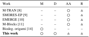
Table 1 shows a comparison of representative prior studies against the four design properties targeted in this study: material circularity (M), intra-module disassembly (D), automatic assembly compatibility (AA), and functional-unit reuse (R). Each property is regarded as a binary attribute: it is either explicitly addressed in the system design and validated, or it is not. Modular robot systems (M-TRAN 8, SMORES-EP 9, EMERGE 10, and M-Blocks 11) support AA through module-level connectors designed for robotic docking; however, their internal components remain monolithically integrated. Therefore, D and R are not addressed or partially addressed. Biodegradable robot designs 14 address M through material selection; however, they are intended for single-use disposable applications, and fail to address D, AA, and R. No prior study has explicitly combined these four perspectives for a complete robot actuator module. The present study addresses them with a complete validation of intra-module disassembly and a preliminary validation of automatic assembly compatibility and repeated functional-unit reuse.
3. Design of Robot Module
This section describes the design of the prototype robot module. Fig. 1 shows the assembled prototype. We detail the structural material selection and each functional unit group.
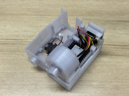
Fig. 1. Assembled prototype of recyclable robot module. Nine functional units are stacked in a brick-like layout and connected through releasable magnetic and mortise-and-tenon interfaces; no screws or adhesives are used.
3.1. Structural Material
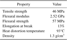
For the structural components of the module (cases and gear housings), the unit-assembly concept requires a material that exhibits the following characteristics: (i) FDM-printable for rapid prototyping of complex geometries; (ii) mechanically adequate at operating stress levels (10–50 MPa); and (iii) recoverable at the EoL, thus satisfying concept A. Conventional FDM materials such as polylactic acid (PLA) and acrylonitrile butadiene styrene (ABS) fulfill (i) and (ii) but offer limited EoL pathways beyond landfill. In this study, cellulose acetate (CA), a biobased thermoplastic (provided by Nature 3D a and manufactured using NEQAS OCEAN b), was used because it offers reprocessing and biodegradation pathways at the EoL 15,16,17. The CA product (NEQAS OCEAN b) is certified for marine biodegradability. Table 2 summarizes its key properties.
A known challenge of FDM-printed CA is its weak interlayer bonding in the \(Z\)-direction (\(<4\) MPa vs. \({\sim}\)40 MPa in \(XY\)). The mortise-and-tenon interface described in the following subsection mitigates this limitation by routing the primary load path through the \(XY\) cross-section of the tenon. The architecture is material-agnostic: any single-component thermoplastic satisfying (i)–(iii) can substitute for CA without modifying the structural design.
Table 2. Mechanical properties of CA pellet (NEQAS OCEAN b).
3.2. Unit-Assembly Structure and Releasable Interfaces
Unlike conventional monolithic robot modules optimized for compactness, our module is composed of nine separable functional units categorized into drivetrain (motor, gear train, and position sensor), cooling 18 (Peltier, heat sink, and fan), and control (PCBs). Each unit can be independently manufactured, replaced, and recovered at the EoL, thus serving all three recyclability concepts. Fig. 2 illustrates the structure and Fig. 3(a) shows photographs of four representative fabricated units.
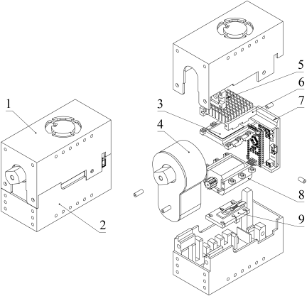
Fig. 2. Unit-assembly structure. Units: 1. Upper case with fan (CA); 2. lower case (CA); 3. peltier unit; 4. gear-train unit (CA); 5. position-sensor unit; 6. heat-sink unit; 7. control unit; 8. motor unit; and 9. temperature-sensor unit.
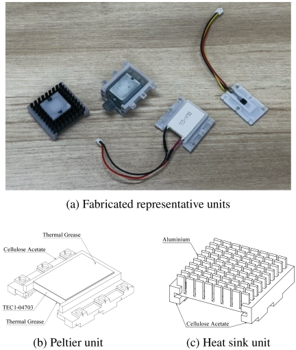
Fig. 3. Representative fabricated units and cooling-unit outlines. (a) Heat sink, motor unit, Peltier unit, and temperature sensor unit (from left to right). The heat sink is an aluminum block with fins, the motor unit comprises a DC motor, the Peltier unit is a thermoelectric cooler, and the temperature sensor unit comprises a TEMP04 sensor. (b) Outline of Peltier unit. (c) Outline of heat-sink unit.
The units are stacked vertically in a brick-like layout connected through three types of releasable interfaces (Fig. 4): neodymium magnets embedded in CA components for self-aligning, tool-less magnetic connections; iron-rod magnetic dowels inserted into magnetized holes to secure the upper and lower cases; and mortise-and-tenon joints that distribute loads across thicker CA cross-sections, thus mitigating the weak interlayer bonding of FDM-printed CA. The top-down stacking order is specifically designed for compatibility with robotic assembly (Section 5) and tool-free disassembly (Section 3.6).
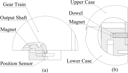
Fig. 4. (a) Magnetic interface between position sensor and gear train units. (b) Magnetic dowel between upper and lower cases.
Although magnetic interfaces are used throughout the module, they are not intended to serve as the primary load-bearing elements. In the assembled state, the drivetrain and motor units are constrained by the nested housing geometry and mechanical limiting features. Consequently, the operational load is primarily transferred through the housing structure instead of directly through the magnetic interfaces. The magnetic interfaces primarily provide positioning, self-alignment, and tool-less releasability, whereas the nested housing constrains relative displacement during operation. This load-path design reduces the dependence on magnetic attraction for structural stability.
However, the prototype is limited to low-load and low-vibration operating conditions, primarily owing to the material and structural implementation of the prototype. The gear train and housing are fabricated from CA, whose strength, fatigue resistance, and vibration stability are lower than those of conventional metal gearboxes and high-performance engineering plastic housings. For high-torque or high-vibration applications, the same unit-assembly concept requires reinforced housing constraints, stronger recyclable structural materials, and additional releasable locking mechanisms.
3.3. Drivetrain Units
The drivetrain comprises a commercial DC motor (FC-280PC), a CA gear train, and a potentiometer (RDC506002) for position feedback. The motor and potentiometer are reusable units that are recoverable through the magnetic interfaces, and the CA gear casing can be recycled as a single-material thermoplastic.
Two four-stage CA gear trains were developed: \({50:1}\) high-torque and \({28:1}\) high-speed variants (Fig. 5). For the high-torque variant, the Lewis bending stress analysis yielded a maximum tooth stress of 14.05 MPa on the critical fourth-stage pinion, with a safety factor \(n_{F} = 2.7\)–\(4.1\) against CA’s allowable stress (38–57 MPa). The Hertz contact pressure (\({\sim}\)7.8 MPa) remains within limits, thus confirming that the CA gears provide adequate strength. Table 3 summarizes the design parameters for both variants.
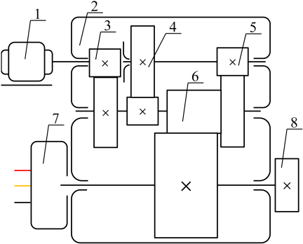
Fig. 5. Kinematic diagram of gear-train unit. 1. Motor shaft; 2. CA casing; 3–6. CA gear pairs; 7. potentiometer; and 8. output shaft.
Table 3. Gear-train design parameters for two drivetrain variants.
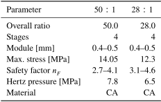
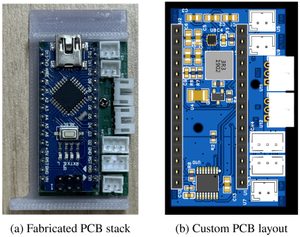
Fig. 6. Control-unit electronics. (a) Fabricated Arduino Nano and custom driver PCB stack. (b) Layout of custom driver PCB, including reserved IN/OUT connectors for external electrical and signal connection.
3.4. Cooling Units
The cooling unit comprises a thermoelectric cooler (Peltier TEC1-04703), an aluminum heat sink, and a fan, all of which are separable from the CA structure via the magnetic interfaces (Figs. 3(b) and (c)). The Peltier unit, heat sink, and fan are individually reusable components, whereas the CA shelf is recyclable. The magnetic interface enables switching between active (with Peltier unit) and passive (without Peltier unit) configurations, thereby extending the service life of the module.
Thermal performance is evaluated in Section 4.
3.5. Control Units
The control unit (Fig. 6) adopts a “double-waffle” stacked PCB architecture in which two boards are coupled exclusively through pin-to-pin connectors—no solder joints exist between boards. The lower custom driver PCB (Fig. 6(b)) integrates a Peltier driver (Monolithic Power MP2329), a dual DC motor driver (Texas Instruments DRV8848), a fan PWM driver, and independent DC-DC voltage regulators providing 12 and 3.3 V rails. The upper board is a commercial Arduino Nano that implements a 50 Hz PID feedback loop using potentiometer position data and issues PWM commands to the DRV8848. A software end-stop limits the shaft rotation to \(\pm270°\) to protect the wiring harness, and the hardware current limit in the DRV8848 prevents stall-induced motor damage, thus directly extending the motor’s reusable service life.
In addition to the intra-module wiring, the custom driver PCB reserves two \(2 \times 3\)-pin connectors—labeled IN and OUT—for intermodule electrical/signal connection. These connectors are intended to transmit power and communication signals between the modules in a daisy-chain configuration. Thus, the control unit supports not only internal functional-unit separation but also external electrical/signal extensibility for multi-module systems. Multi-module communication through these ports is a design provision that must be validated in future multi-module experiments.
For component reuse, each board can be replaced or recovered independently, the pin-to-pin interface is fully releasable, and signal lines (motor PWM, potentiometer feedback, and temperature sensor) are routed through short wire harnesses with polarized micro-connectors for error-free reconnection after disassembly. The PID gains (\(K_p\), \(K_i\), and \(K_d\)) are stored in the firmware and can be re-uploaded to a replacement Arduino Nano without hardware modifications.
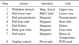
Table 4. Disassembly sequence: each step uses no tools (magnetic pull or tenon slide).
3.6. Easy Disassembly and Exchangeability of Units
This subsection evaluates requirement R1 based on the tool-free disassembly of the module. The functional performance after reassembly is validated in Section 4, thereby confirming unit exchangeability.
Table 4 details the disassembly sequence. Beginning from the topmost unit, eight pull or slide operations—all tool-free—are sufficient to separate the module into clean material streams. Full disassembly was completed within 90 s by a practiced operator; the high-priority motor unit (primary reuse target) is accessible after Step 6.
Figure 7 shows the photographs corresponding to the eight sequential steps. No unit was damaged during disassembly, and repeated-use functional performance is evaluated in Section 4.2.
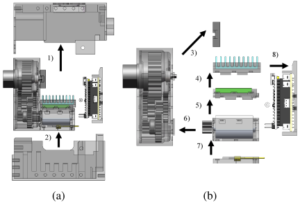
Fig. 7. Sequential disassembly of functional units (Steps 1–8, from A to B). Each step is a single tool-free pull or slide operation.
4. Functional-Performance Validation
This section evaluates whether the unit-assembly design preserves module performance after repeated assembly-disassembly cycles. The drivetrain control performance was measured under load, and repeated-use tests were conducted for up to 120 assembly-disassembly cycles. Additionally, cooling performance was also evaluated to confirm that the separable cooling units remained functional after reassembly.
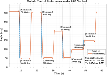
Fig. 8. Drivetrain control performance (24 °C, 12 V, 0.05 Nm load). Blue: commanded; orange: measured. Settling time \(T_s\) refers to the time to reach and remain within \(\pm2\)% of the final value; rise time \(T_r\) refers to the time to increase from 10% to 90% of the final value; steady-state error \(E_{ss}\) is the final position error; overshoot OS is the percentage overshoot relative to the target.
4.1. Drivetrain-Control Performance
Experiments were conducted to evaluate the drivetrain under step inputs at two load levels (0.05 and 0.10 Nm). Fig. 8 shows the representative response at 0.05 Nm. Across the tested commands and loads, the drivetrain achieved settling times of 0.61–3.24 s, steady-state errors between \(-4.17°\) and \(4.00°\), and overshoots of less than 13.5%. Although the settling time increased slightly at higher loads owing to the gear-tooth compliance and static friction, the system maintains stable closed-loop positioning across the full range. These results confirm that the recyclable CA-based drivetrain does not compromise the control performance in the intended operating regime.
4.2. Multi-Cycle Reuse Evaluation
To provide preliminary evidence for the repeated reuse of the functional unit, the same module was repeatedly assembled and disassembled for 120 cycles. Control-performance tests (Fig. 9) were conducted after every 20 cycles under a 0.05 Nm load. At each cycle, nine step responses were recorded using command amplitudes from 50° to 250°: two 100° steps, one 150° step, four 50° steps, one 250° step, and one 200° step. The rise time, settling time, overshoot, and steady-state error were calculated for each step response and then averaged over the tested commands. Fig. 9 shows the evolution of these metrics as a function of the number of assembly-disassembly cycles. A slight degradation was observed after 100–120 cycles; however, the resulting positioning error remained within the control tolerance required for the intended low-load operating regime. The slight performance decline is likely due to minor gear wear in the gear train unit, which is the most mechanically stressed component; however, it did not significantly affect the overall functionality.
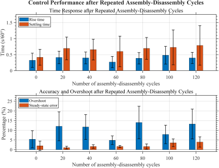
Fig. 9. Drivetrain-control performance after repeated assembly-disassembly cycles under 0.05 Nm load. Rise time and settling time are plotted on top subplot, while overshoot and steady-state error are plotted on bottom subplot. The metrics were calculated from nine step-response trials at each cycle number. Error bars represent standard deviation across trials.
4.3. Cooling Performance
COMSOL transient thermal simulations (180 s, motor heat generation 2.5 W, ambient 20 °C) confirmed that active cooling reduced the motor temperature to \({\sim}\)20 °C, whereas passive cooling only reached \({\sim}\)28.5 °C (Fig. 10). Actual experiments (12 V, 0.1 Nm load, 24 °C ambient) validated these results: the active cooling system cooled the motor to room temperature within 200 s, as compared with \(>3000\) s for passive cooling (Fig. 11). Taken together, the drivetrain, multi-cycle reuse, and cooling evaluations confirm that unit exchangeability does not degrade functional performance.
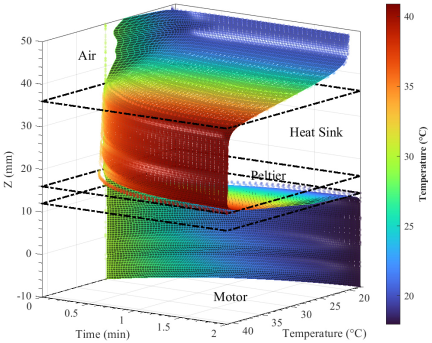
Fig. 10. COMSOL transient simulation of active cooling (\(Z\)-axis cross-section). After 180 s, motor temperature reached \({\sim}\)20 °C.
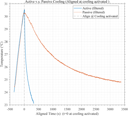
Fig. 11. Cooling performance: active (blue) vs. passive (orange) (24 °C, 12 V, 0.1 Nm).
5. Automatic Assembly as Recyclability Enabler
This section evaluates the compatibility of the proposed releasable interfaces with robotic assembly. A 4-DOF robot arm and a YOLOv8-based pose-estimation pipeline were used to assemble a representative subset of the four functional units.
5.1. System Overview
The system (Fig. 12) comprises a Dobot Magician robot arm (4 DOF), an Intel RealSense D435i RGB-D camera, and a PC operating ROS Noetic. ArUco markers provide camera–robot calibration. The workflow is as follows: (i) the camera captures component images; (ii) a YOLOv8-based [19, 20, c] network detects components and estimates two-dimensional (2D) keypoints; (iii) keypoints are aligned to class-specific templates via rigid-body fitting to obtain planar poses \((u,v,\theta)\); (iv) assembly trajectories are planned and executed.
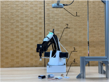
Fig. 12. Automatic assembly system. (1) RGB-D camera; (2) dobot magician; (3) ArUco calibration markers; and (4) components for assembly.
5.2. Component Recognition and Pose Estimation
We adopted a YOLOv8-pose architecture [19, 20, c] that simultaneously predicts the bounding boxes, class labels, and 2D keypoints for each detected instance. The planar pose \((u,v,\theta)\) was recovered by fitting predicted keypoints to a class-specific geometric template via least-squares rigid-body alignment; for near-symmetric components, a symmetry-breaking keypoint (e.g., a unique notch pattern) was included in the template to resolve orientation ambiguity.
The model (YOLOv8s-pose, fine-tuned from ImageNet pretrained weights) was trained for 50 epochs (batch 32, image size \(640 \times 640\)) on a custom dataset captured five component classes (Peltier unit, motor unit, heat sink, gear train unit, and temperature sensor) under representative illumination, partial occlusions, and surface reflections. The dataset included the gear-train unit as it is one of the nine functional units in the complete module and is required for future extension to full nine-unit assembly, although it was not manipulated in the present four-unit experiment. Data augmentation included random flips, hue-saturation-value jitter, and mosaic compositing (disabled for the final 10 epochs) to improve robustness. Table 5 lists the overall detection and keypoint metrics for the held-out validation set at the final epoch. The mean keypoint localization error in the pixel space translates to 1–2 mm positional and 2°–5° orientation errors in the robot base-frame coordinates (Fig. 13).
Table 5. YOLOv8s-pose validation metrics at epoch 50 (five classes, all-class average).
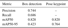
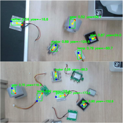
Fig. 13. Component detection and pose estimation examples.
5.3. Assembly Experiments and Results
Components were randomly placed on a table, and the robot arm assembled them in a predefined sequence. The system successfully assembled the temperature sensor, motor, Peltier unit, and heat-sink unit (Fig. 14), thus achieving an average cycle time of 40 s per module. Although the perception dataset recognizes five unit classes, the current experiment manipulates only the four representative units above; the gear-train unit is included in the dataset to support full nine-unit assembly in the future, but does not constitute the demonstrated four-unit sequence. The magnetic self-aligning interfaces proved to be critical; in cases where vision-based placement was slightly off-target (1–2 mm), the magnetic attraction corrected the final alignment. This indicates that the proposed releasable interfaces can tolerate the positioning uncertainty of a simple fixed-camera with a 4-DOF assembly setup, which approximates the hardware constraints of common factory SCARA-style automation. For the mortise-and-tenon joints (\(<1\) mm tolerance), vision accuracy alone can be insufficient. The 4-DOF constraint limited assembly to top-down operations.
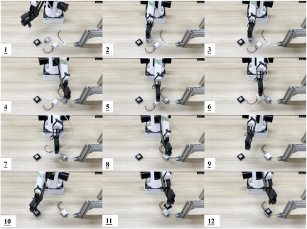
Fig. 14. Verification test: robot arm retrieves and assembles four functional units.
Therefore, the current experiment should be interpreted as a proof-of-concept validation of interface-level assembly compatibility instead of as a production-yield benchmark. Unsuccessful trials were primarily caused by residual orientation error (\(> 5 °\)) after pose estimation; the present magnetic self-alignment compensates for translational errors (\(<2\) mm) but provides limited passive correction for rotational misalignment. This result suggests two system-level improvement directions: redesigning the magnetic interfaces with rotational self-indexing features and replacing/supplementing the eye-to-hand camera with an eye-in-hand configuration to provide localized visual feedback during the final insertion.
These results support the compatibility of the proposed releasable interfaces with robotic manipulation at the interface level. Because the same interfaces are designed to be released in the reverse direction, the results suggest a feasible pathway for future automated disassembly. However, direct validation of robotic disassembly remains a topic for future investigation.
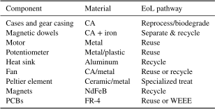
Table 6. Material composition and EoL pathway.
6. Recyclability Evaluation
Table 6 summarizes the material composition and EoL pathway of each component. CA constitutes \({\sim}\)70% of the total mass; combined with reusable electronics and recyclable metals, approximately 71% of the total module mass (\({\sim}\)213 g out of 300 g) is recyclable or biodegradable. Using the Ellen MacArthur Foundation Material Circularity Indicator methodology 21, the estimated MCI is 0.68–0.71, which is substantially higher than that of a conventional steel/FR-4 monolithic module (\(<0.30\), estimated).
7. Conclusions and Future Studies
This study proposed and validated a unit-assembly architecture for robot modules as a structural pathway for recyclable robots. It is based on three recyclability concepts: (A) material circularity, (B) structural recyclability, and (C) functional-unit reuse. Focusing on concepts B and C, two interface-level requirements—easy disassembly (R1) and automatic assembly compatibility (R2)—were formulated and evaluated experimentally. The key findings are as follows:
-
R1 validated: The module was fully disassembled into nine functional units in eight tool-free pull or slide operations with no screws, adhesives, or specialized tooling. The drivetrain (\(T_{s} \sim 0.9\) s, \(E_{ss} \sim 1°\)) and cooling (room temperature within 200 s) performances were preserved after reassembly, thus confirming unit exchangeability.
-
Repeated-use validation: The module was subjected to 120 assembly-disassembly cycles, and the drivetrain performance was measured every 20 cycles. The results showed limited degradation of the positioning performance within the tested range, thus providing preliminary support for the reuse of the functional-unit.
-
R2 partially validated: A 4-DOF arm with YOLOv8-based vision (\(\textrm{mAP50} = 0.828\)) assembled a subset of four representative units, thus demonstrating interface-level assembly compatibility under simplified factory-like conditions. The full nine-unit assembly remains a topic for future investigation.
-
Using CA as the structural material yielded approximately a recyclable or biodegradable mass fraction of 71% (\(\textrm{MCI} \approx 0.68\)–0.71); the unit-assembly architecture is material-agnostic and applicable to any suitable single-component thermoplastic.
Three key areas were identified for future investigation:
-
Automated robotic disassembly: The symmetric releasable interfaces may allow the same vision and trajectory framework to be adapted for robotic disassembly in future studies.
-
Long-term durability evaluation: Larger cycle numbers, vibration loadings, and quantitative retention-force measurements should be considered to evaluate the long-term degradation of the releasable interfaces.
-
Assembly system improvements: Future systems should improve the rotational alignment through rotational self-indexing magnetic interfaces, eye-in-hand visual feedback for the final insertion, and/or depth-based pose refinement. A 6-DOF arm would facilitate full nine-unit stack handling.
Acknowledgments
This study was supported by JSPS KAKENHI Grant Number 23K03771. The authors thank Jiaxin Peng and Kazuho Daicho for their advice and discussions.
- [1] A. Jurkat, R. Klump, and F. Schneider, “Tracking the rise of robots: The IFR database,” Jahrb. Nationalökon. Stat., Vol.242, Nos.5-6, pp. 669-689, 2022. https://doi.org/10.1515/jbnst-2021-0059
- [2] Y. Asano et al., “A sensor-driver integrated muscle module with high-tension measurability and flexibility for tendon-driven robots,” 2015 IEEE/RSJ Int. Conf. Intell. Robots Syst. (IROS), pp. 5960-5965, 2015. https://doi.org/10.1109/IROS.2015.7354225
- [3] C. Favi, M. Marconi, M. Germani, and M. Mandolini, “A design for disassembly tool oriented to mechatronic product de-manufacturing and recycling,” Adv. Eng. Inform., Vol.39, pp. 62-79, 2019. https://doi.org/10.1016/j.aei.2018.11.008
- [4] P. Vanegas et al., “Ease of disassembly of products to support circular economy strategies,” Resour. Conserv. Recycl., Vol.135, pp. 323-334, 2018. https://doi.org/10.1016/j.resconrec.2017.06.022
- [5] Z. Zhang et al., “Recyclable vitrimer-based printed circuit boards for sustainable electronics,” Nat. Sustain., Vol.7, No.5, pp. 616-627, 2024. https://doi.org/10.1038/s41893-024-01333-7
- [6] J. K. Gershenson, G. J. Prasad, and Y. Zhang, “Product modularity: Definitions and benefits,” J. Eng. des., Vol.14, No.3, pp. 295-313, 2003. https://doi.org/10.1080/0954482031000091068
- [7] Y. Zou et al., “Towards robot modularity—A review of international modularity standardization for service robots,” Robot. Auton. Syst., Vol.148, Article No.103943, 2022. https://doi.org/10.1016/j.robot.2021.103943
- [8] S. Murata et al., “M-TRAN: Self-reconfigurable modular robotic system,” IEEE/ASME Trans. Mechatron., Vol.7, No.4, pp. 431-441, 2002. https://doi.org/10.1109/TMECH.2002.806220
- [9] C. Liu, Q. Lin, H. Kim, and M. Yim, “SMORES-EP, a modular robot with parallel self-assembly,” Auton. Robots, Vol.47, No.2, pp. 211-228, 2023. https://doi.org/10.1007/s10514-022-10078-1
- [10] R. Moreno and A. Faiña, “EMERGE modular robot: A tool for fast deployment of evolved robots,” Front. Robot. AI, Vol.8, Article No.699814, 2021. https://doi.org/10.3389/frobt.2021.699814
- [11] J. W. Romanishin, K. Gilpin, and D. Rus, “M-blocks: Momentum-driven, magnetic modular robots,” 2013 IEEE/RSJ Int. Conf. Intell. Robots Syst., pp. 4288-4295, 2013. https://doi.org/10.1109/IROS.2013.6696971
- [12] N. M. P. Bocken, I. de Pauw, C. Bakker, and B. van der Grinten, “Product design and business model strategies for a circular economy,” J. Ind. Prod. Eng., Vol.33, No.5, pp. 308-320, 2016. https://doi.org/10.1080/21681015.2016.1172124
- [13] J. Saenz et al., “Automated disassembly of e-waste—Requirements on modeling of processes and product states,” Front. Robot. AI, Vol.11, Article No.1303279, 2024. https://doi.org/10.3389/frobt.2024.1303279
- [14] P. Wei et al., “Biodegradable origami enables closed-loop sustainable robotic systems,” Sci. Adv., Vol.11, No.6, Article No.eads0217, 2025. https://doi.org/10.1126/sciadv.ads0217
- [15] M. G. Mazzotta, C. M. Reddy, and C. P. Ward, “Rapid degradation of cellulose diacetate by marine microbes,” Environ. Sci. Technol. Lett., Vol.9, No.1, pp. 37-41, 2022. https://doi.org/10.1021/acs.estlett.1c00843
- [16] A. Gallet-Pandellé, R. G. Rinaldi, F. Dalmas, H. Kurita, and F. Narita, “On the use of cellulose acetate as a structural material for parts produced by fused filament fabrication,” Cellulose, Vol.31, No.15, pp. 9265-9279, 2024. https://doi.org/10.1007/s10570-024-06092-4
- [17] G. Gadaleta et al., “Degradation of thermoplastic cellulose acetate-based bioplastics by full-scale experimentation of industrial anaerobic digestion and composting,” Chem. Eng. J., Vol.462, Article No.142301, 2023. https://doi.org/10.1016/j.cej.2023.142301
- [18] K. Hayashi, Y. Asano, Y. Nishikawa, and J. Shiomi, “Design concept of robot actuator module with passive cooling by heat transfer among close contact components,” 2024 IEEE/SICE Int. Symp. Syst. Integr. (SII), pp. 1211-1216, 2024. https://doi.org/10.1109/SII58957.2024.10417207
- [19] K. Sun, B. Xiao, D. Liu, and J. Wang, “Deep high-resolution representation learning for human pose estimation,” 2019 IEEE/CVF Conf. Comput. Vis. Pattern Recognit. (CVPR), pp. 5686-5696, 2019. https://doi.org/10.1109/CVPR.2019.00584
- [20] M. Sohan, T. Sai Ram, and C. V. Rami Reddy, “A review on YOLOv8 and its advancements,” Int. Conf. Data Intell. Cogn. Inform., pp. 529-545, 2024. https://doi.org/10.1007/978-981-99-7962-2_39
- [21] M. Niero and P. P. Kalbar, “Coupling material circularity indicators and life cycle based indicators: A proposal to advance the assessment of circular economy strategies at the product level,” Resour. Conserv. Recycl., Vol.140, pp. 305-312, 2019. https://doi.org/10.1016/j.resconrec.2018.10.002
- [a] Nature 3D, “Cellulose Acetate Filament.” https://nature3d.thebase.in/items/66101734 [Accessed November 25, 2025]
- [b] NEQAS Corporation, “NEQAS OCEAN.” https://neqas.co.jp/neqas-ocean/ [Accessed November 25, 2025]
- [c] Ultralytics, “YOLOv8.” https://github.com/ultralytics/ultralytics [Accessed February 25, 2026]
This article is published under a Creative Commons Attribution-NoDerivatives 4.0 Internationa License.