
Paper:
Proposal of a Flexible Sensor with an Inflatable Structure in Learning Pressure Massage Techniques
Yasutaka Nishioka*
 , Hitoshi Yamauchi*, Keiko Seki**, Shinya Nakajima***, and Junpei Kato***
*Department of Mechanical System Engineering, The University of Shiga Prefecture
2500 Hassaka, Hikone, Shiga 522-8533, Japan
**Department of Human Nursing, The University of Shiga Prefecture
2500 Hassaka, Hikone, Shiga 522-8533, Japan
***Department of Kyoto Kagaku Corporation
15 Kitanegoya-cho, Fushimi-ku, Kyoto, Kyoto 612-8388, Japan

Massage has both physical and mental benefits. Pressure massage is suitable for exerting a strong force on the skin’s surface in the normal direction. This technique is taught visually or using force feedback. Quantitative evaluation and learning methodologies are required. In this study, we propose a learning support system for massage techniques. The applied force and angle are quantitatively evaluated. Large forces, such as those applied during a massage, are difficult to measure using conventional rigid sensors or sensors incapable of handling large displacements. Therefore, we propose a flexible three-axis force sensor with an inflatable structure using pneumatics. The sensor is made of a non-elastic material; therefore, it can measure large forces based on volume changes. We show the design and construction of the proposed sensor and evaluate it.
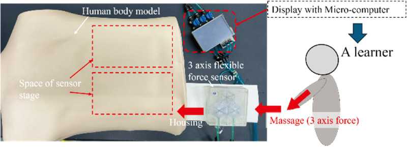
Schematic of pressure massage learning support system
1. Introduction
With the aging of the Japanese population, the demand for massage and shiatsu as preventive medicine in nursing care facilities is expected to increase [1–6]. Massage and shiatsu, which are widely used in Japan, increase body surface temperature, improve flexibility, and relieve mental tension 4,5,6. Massage and shiatsu training facilities provide practical and clinical training. Efforts have been made to clarify the details of training content and unify the evaluation criteria; however, an objective evaluation remains difficult 7,8.
Pressure massage is a technique in which a practitioner applies pressure to acupuncture points with their hands. The amount of force applied to the patient’s body, angle relative to the skin, and point at which the force is applied are all important. The instructor demonstrates how to perform the pressure massage technique to students during practical instruction. The instructor then evaluates the student as the student performs the technique, or visually evaluates the student while performing the technique. These evaluation methods are subjective; thus, the results vary depending on the instructor. In addition, because the instructor and students must perform the technique simultaneously, independent learning is difficult.
Several systems have been developed to help students learn massage techniques 9,10,11. A learning system was developed to visually convey quantitative feedback on massage techniques to learners based on data measured using IoT devices 9,10. Tojo et al. developed a learning support system called the massage score reader system (MRS) to quantitatively evaluate and teach thumb compression 11. The MRS records data on the treatment surface pressure between the skin of the therapist and patient. It measures the change in surface pressure over time using a musical scale based on body parts and volume. The system allows for playback using a MIDI sound source built into a computer and the electronic storage of data files. Practical skill evaluation using the MRS showed that this system enabled efficient learning.
To develop a learning support system for pressure massage techniques, it is necessary to detect the angle of the force applied to the skin. This can be achieved using a three-axis force sensor. However, most multi-axis force sensors combine a highly rigid structure with a strain gauge, and the displacement in the direction of the applied force is minimal, resulting in a sensation of pressure that differs from that of the human body. Flexible tactile sensors include sheet-like sensors that detect pressure by sensing the displacement caused by a force applied to an elastic body. However, these sensors only target pressure in the direction perpendicular to the sheet surface 12,13,14,15,16. Flexible multi-axis force sensors have been developed 17,18,19,20,21,22,23,24,25,26, but there have been no reports of measuring forces greater than 20 N. Thus, these sensors cannot measure the forces applied during massage.
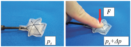
Fig. 1. Flexible force sensor with inflatable structure.
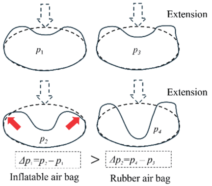
Fig. 2. Principle of inflatable structure.
The massage force applied by experts and learners was measured. The maximum measured force was 92.2 N. To measure the high forces applied in massage, the present study proposes a flexible sensor with an inflatable structure, shown in Fig. 1. An inflatable structure is an airbag made of a non-elastic material. Low-density polyethylene was used in this study (AICELLO Co.). A certain degree of rigidity was achieved by inflating the airbag. The differences between the proposed and existing rubber sensors are shown in Fig. 2. We assume that an external force is applied to the structure. Because the proposed sensor’s material is non-elastic, the external force can be estimated based on the increase in internal pressure caused by the change in volume. Because the material does not stretch, even low pressure provides adequate rigidity, making the structure less prone to collapse. Nakamura et al. proposed a cushion-shaped structure with sufficient thickness relative to an air chamber to serve as a flexible sensor for robot arms 26.
An overview of the proposed pressure massage system is shown in Fig. 3. This system supports learning by providing real-time feedback on the applied force when a learner applies a force similar to that used in pressure massage treatment. It has been suggested that an appropriate magnitude and direction of force are important when applying pressure massage. It is important to maintain a constant large force and slow release. In addition, if force is not applied in the direction normal to the muscle fibers, damage to the muscle fibers and skin may occur. The human body model used in this study is composed of a flexible human body dummy (Kyoto Kagaku Co., Ltd.) and the proposed flexible three-axis force sensor. As shown in the figure, a stand with a fixed sensor was inserted under the back model. The information detected by the sensor was input into a microcomputer and displayed. For the learning support system device to have the ability to sense three-axis forces and have flexibility similar to that of the human body, we developed a flexible three-axis force sensor using flexible silicone rubber and an inflatable structure made of a polymer material film.
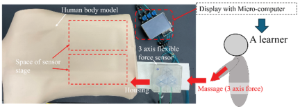
Fig. 3. Schematic of pressure massage learning support system.
2. Design of Flexible Force Sensor with Inflatable Structure
2.1. Principle
The flexible force sensor was an airbag (made by heat-welding a film) connected to a pressure sensor and a valve by a tube. It can be used as a force sensor by inflating an airbag and then closing and sealing the valve. When an external force is applied to an inflated airbag, the volume decreases while the internal pressure increases. The external force was estimated using the increase in internal pressure. Sugano et al. conducted a study on external force estimation using a force sensor with a film airbag 28. They discovered when an external force was applied to a film airbag using a rigid plate with a sufficiently large area, the relationship between the external force and internal pressure differed from that of a general air cylinder. This is expressed as follows 27.
In this study, the contact area \(A\) between the airbag and rigid plate is expressed as a function of \(x\). This is because if the airbag is pressed against a sufficiently large rigid plate, it collapses as displacement \(x\) increases. In pressure massage, an external force is applied to the finger pads, which have relatively small areas. The contact area \(A\) is assumed to remain unchanged, except when the displacement \(x\) is small.
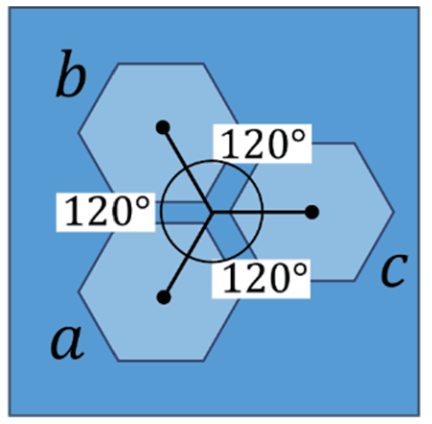
Fig. 4. Arrangement of three airbags.
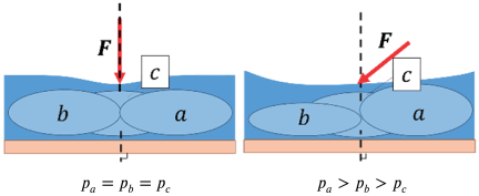
Fig. 5. Schematic of flexible three-axis force sensor.
Three flexible force sensors were combined to estimate the force in the three axial directions. Fig. 4 shows the arrangement of the airbags inside the flexible three-axis force sensor. The airbags for the three flexible force sensors are arranged symmetrically on the same plane and point.
Figure 5 shows the principle as seen from the side. When a force is applied in the plane’s normal direction, it can be considered that the volumes of the three flexible force sensors \(a\), \(b\), and \(c\) decrease equally, while the internal pressures \(p_a\), \(p_b\), and \(p_c\) increase equally. When an external force with a shear component was applied, the airbag’s internal pressure in the inclined shear direction increased more than those of the other airbags. The shear component of the external force \(F\) is directed toward airbag \(a\), indicating that the internal pressure \(p_a\) is greater than \(p_b\) and \(p_c\) as shown on the right side of Fig. 5. When an external force was applied between airbags \(b\) and \(c\), the pressure changes in \(p_b\) and \(p_c\) increased more than those in \(p_a\).
The proposed sensor estimates the magnitude and gradient of the input force in three axial directions based on changes in the internal pressure of the three airbags.
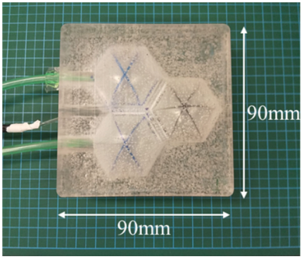
Fig. 6. Fabricated flexible three-axis sensor.
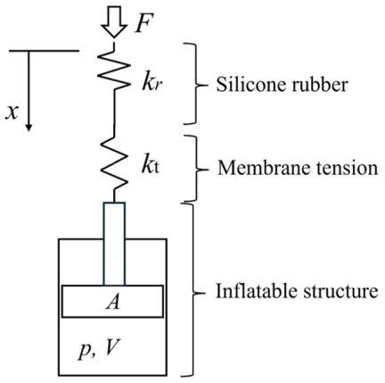
Fig. 7. Conceptual model of the prototype flexible sensor.
2.2. Manufacturing Method
The airbag was fabricated by heat-welding a regular hexagonal film with a side length of 18 mm. Subsequently, liquid silicone rubber (Shin-Etsu Silicone Corp., KE-1606) was poured into a mold shape resembling three inflated airbags and allowed to harden, resulting in a sensor fixture with three recesses. Two silicone rubber fixtures were used to sandwich the three inflated airbags. The silicone rubber was allowed to harden again. Fig. 6 shows the manufactured flexible sensor with inflatable airbags. A conceptual model in which an airbag is treated as a single elastic body is shown in Fig. 7. From this model, the following equation can be derived by adding the elastic force of the silicone rubber to Eq. (1) as follows:
Assuming a constant initial internal pressure, it can be approximated as a model in which three types of elastic elements are connected in series.
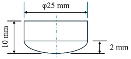
Fig. 8. Tip shape of the force gauge for pressing the sensor.
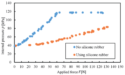
Fig. 9. Comparison of internal pressure increase with applied force between sensor with and without silicone rubber.
2.3. Basic Experiment
We experimentally verified the feasibility of measuring the target force. Two types of airbags were used in the experiment: an airbag alone and an airbag covered in silicone rubber, as shown in Fig. 6. A force gauge was placed in the \(Z\)-axis direction, and the sensor was compressed. The shape of the force gauge’s tip is shown in Fig. 8. It is approximated as an elliptical curved surface with a surface area similar to that of a thumbpad. This shape was produced using a 3D printer equipped with a PLA resin. The internal pressure was measured using a pressure sensor (Qwiic Micro Pressure sensor, SparkFun) connected to nearby airbags. Fig. 9 shows the relationship between the external force and internal pressure when an external force is applied to the airbag part of the flexible force sensor.
For the sensor without the silicone rubber, the internal pressure stopped increasing at approximately 60 N. This is because the airbag was crushed, and the volume remained constant even as the applied force increased. However, for the sensor with the airbag part covered with silicone rubber, the internal pressure increases even after exceeding 110.6 N. For the model not covered with silicone rubber, displacement \(x\) was the upper limit above this force range. Because the volume does not change, it is inferred that all the terms in Eq. (3) will have constant values. In addition, the change in volume because of the external force was reduced owing to the reinforcement by silicone rubber (Shin-Etsu Silicone Co.). The relationship between the external force and the internal pressure of the flexible force sensor with the airbag part covered with silicone rubber was flat up to approximately 30 N and then showed an almost linear increase. Up to approximately 30 N, an insensible area may occur owing to the small gap between the rubber case and the airbag sensor. According to these results, this study considers the initial internal pressure as a constant and approximates the relationship between the force and pressure as linear by approximating the three types of elastic elements shown in Eq. (3) as elastic elements connected in series.
In this case, the relationship between the output value and the three-axial forces is expressed as follows:
2.4. Measurement of Coefficient Matrix
The coefficient matrix \(\boldsymbol{C}\) in Eq. (8) can be obtained by dividing the internal pressures \(\Delta p_a\), \(\Delta p_b\), and \(\Delta p_c\) when each axial force is applied independently by the force scalar. However, because of the nature of the experimental equipment, it was difficult to apply \(F_x\) and \(F_y\) independently. Therefore, \(\boldsymbol{F}=[0\ \, 0\ \, F_z]^{\textsf{T}}\), \(\boldsymbol{F}=[F_x\ \, 0\ \, F_z]^{\textsf{T}}\), and \(\boldsymbol{F}=[0\ \, F_y\ \, F_z]^{\textsf{T}}\) were applied and \(\Delta p_a\), \(\Delta p_b\), and \(\Delta p_c\) were measured to obtain the elements of the coefficient matrix. The coefficients at which each force was applied are determined as follows:
3. Coefficient Matrix Measurement Experiment
3.1. Experimental Method
The experimental setup is shown in Fig. 10. A force gauge was used to apply force to the three-axis force sensor (USL08-H6-1KN-A, Tec Gihan Co.). A jig with the same inclination as that of the triangular prism-shaped base was used. A fixture with no inclination and one with an inclination angle of 20° were used.
A three-axis force sensor was attached to the experimental equipment using a non-inclined jig, and a flexible three-axis force sensor was placed on the stage. A flexible three-axis force sensor was installed such that the center between the airbag sections was below the origin of the pressure-receiving section of the three-axis force sensor. The airbag section of the flexible three-axis force sensor was filled with air and sealed. The initial internal pressure was set at 40 kPa. This value was determined after discussions with massage experts. The three-axis force sensor was pressed against a flexible three-axis force sensor to apply force. The applied force was gradually increased until it reached 110 N. The force was removed, and the recording ended. Subsequently, a tilted jig was used to determine the relationship between force and internal pressure in the same manner.
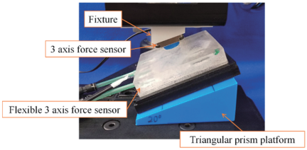
Fig. 10. Photograph of experimental setup.
3.2. Experimental Results
Figures 11–13 show the experimental results obtained when the force was applied in different directions. The vertical axis shows the change in internal pressure, while the horizontal axis shows the magnitude of the applied force. The experimental results show that the \(R\)-squared value was \(<0.98\). Eq. (6) assumes that the force and change in internal pressure are linear. For the experimental results, we focused on the case in which the applied force was small. In particular, when the applied force is 30 N or less, the slope changes significantly. The nonlinearity of each graph was high. The experts’ preliminary experimental results indicated that the maximum force in the pressure massage was 50 N or more. Additionally, a preliminary experiment revealed that the transient change when force was applied was likely to be effective in evaluating the massage technique. It is believed that the section where the maximum force is maintained, as well as the changes in the rising and falling sections close to that section, are important. Thus, we decided not to evaluate the change when the force was small and set the applied force range to 30 N or more. Estimating the low-force region remains a future challenge. The coefficient matrix was calculated using the slope. The following matrix was obtained:
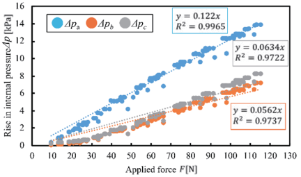
Fig. 11. Relationship between force \(F\) and internal pressures \(\Delta P_{a1}\), \(\Delta P_{b1}\), and \(\Delta P_{c1}\).
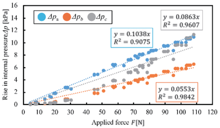
Fig. 12. Relationship between force \(F\) and internal pressures \(\Delta P_{a2}\), \(\Delta P_{b2}\), and \(\Delta P_{c2}\).
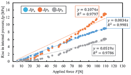
Fig. 13. Relationship between force \(F\) and internal pressures \(\Delta p_{a3}\), \(\Delta p_{b3}\), and \(\Delta p_{c3}\).
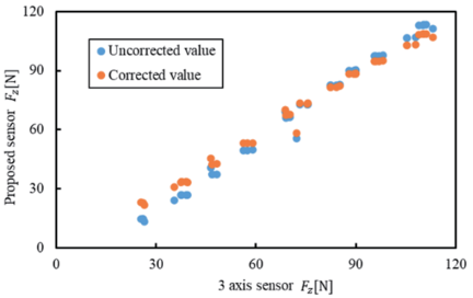
Fig. 14. Comparison of three-axis and proposed sensor in terms of normal component \(F_z\).
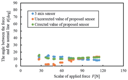
Fig. 15. Comparison of angle \(\theta\) versus applied force before and after correction.
4. Experimental Evaluation
4.1. Basic Evaluation
As a basic evaluation, we compared the sensor output when a force was applied at a fixed angle of 10° between the conventional three-axis force sensor and the proposed flexible three-axis sensor. Using the same experimental method as shown in Fig. 8, we attached a jig with a 10° inclination and a triangular prism-shaped base with a 10° inclination, then mounted the flexible three-axis force sensor on top of the base. Fig. 14 shows the normal component \(F_z\) of the applied force, with the horizontal axis representing the measured values from a conventional three-axis force sensor and the vertical axis representing calculated values obtained by substituting the internal pressure rise value of the flexible three-axis force sensor into Eq. (6). The data obtained before and after correction are described in Section 3.2. It can be observed that the measured values corrected in the range of 30 N or more are plotted near the diagonal line of the graph.
Figure 15 shows the relationship between the angle estimated from each directional component of the force and the applied force for the three-axis and the proposed sensors. The conventional three-axis force sensor showed a constant output of approximately 10° when a force was applied. For the flexible three-axis force sensor, the data after correction showed an approximately constant output, which was close to the output of the conventional three-axis force sensor.
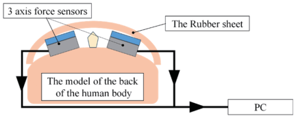
Fig. 16. Diagram of actuator with small volume.
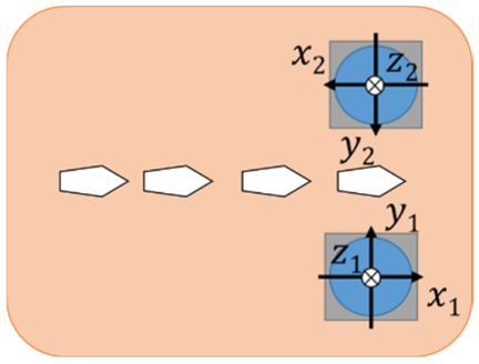
Fig. 17. Diagram of the back model with three-axis force sensors.
4.2. Field Experiment
In pressure massage, it is important to apply force in the normal direction relative to the subject’s skin. Therefore, in this study, we focused on the magnitude of the applied force \(F\) and the angle \(\theta\) between the force applied during pressure massage and the normal to the skin. We conducted an experiment to measure \(F\) and \(\theta\), which can be calculated from the normal component \(F_z\) and shear component \(F_{xy}\) of the applied force to the skin.
The experimental equipment consisted of two small three-axis force sensors (USL08-H6-1KN-A, Tec Gihan Co.), a model of the back of the human body for housing flexible sensors (hereafter referred to as the back model), a rubber sheet that imitates the skin, and a personal computer with software installed to measure the force sensor data. The experimental setup is shown in Fig. 16. Fig. 17 shows a schematic of the back model with the built-in three-axis force sensors. The spinal column was placed at the center of the back model as a landmark to identify its positional relationship with the sensor.
Figure 17 shows the arrangement of the \(X\)-, \(Y\)-, and \(Z\)-axes of the flexible three-axis force sensor. It is possible to measure the normal component \(F_z\) of the force applied to the two sensors’ pressure-receiving surfaces as well as the independent components \(F_x\) and \(F_y\) in the shear direction. The applied force is calculated using the measured \(F_{xy}\) and \(F_z\).
Figure 18 shows an example of the change in force and angle over time, as determined by experts. The angle estimated using the three-axis force components is shown on the right vertical axis. An expert can maintain a constant angle of 10° or less while applying force. The application and release of force are important elements of pressure massage.
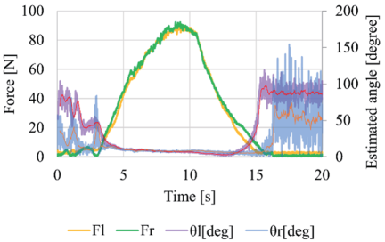
Fig. 18. Variation of force and angle with time by using a conventional 3-axis force sensor.
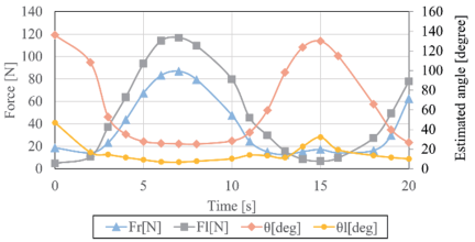
Fig. 19. Comparison of variation of force and estimated angle with time before and after correction.
Figure 19 shows an example of the experimental results from the field evaluation. In the experiment shown in Fig. 18, an expert applied pressure to the flexible sensor placed on the back of the model, as shown in Fig. 15. The results exhibit a tendency similar to that shown in Fig. 15. The magnitude of the force was approximately equivalent to that of a conventional sensor. It can be observed that a constant angle is maintained when a force is applied. After the force was removed, the angle increased. This indicates that the hand moved away from the sensor and a larger angle was observed owing to the calculation of the force in the shear direction. Both results show a trend similar to that shown in Fig. 18. That is, the farther away the hand, the larger the measured value. It is believed that while the force is applied, the angle is also measured at a similar value to the result in Fig. 18. To incorporate the sensor, we are currently developing a model with a shape similar to that of the human body. The back of the human body was inclined, and the skin was placed on the sensor. The characteristics of the sensors installed in the model will be evaluated in future studies.
In addition to the maximum force and angle values, transient changes in the force should be used to evaluate the massage technique. The change in the force over time, which is appropriate for the human body, is an important parameter. It is also necessary to consider the educational effects of this system. The purpose of this experiment was to propose a system configuration and compare the magnitude of the force between the left and right hands and the maximum value to be compared with that of an expert. In this field-measurement experiment, we received the opinion that the first step would be to qualitatively compare the differences between experts and learners, leading to the development of new learning methods.
5. Discussion
5.1. Airbag Sensor Features
Many force sensors use flexible materials, such as silicone rubber. As mentioned in Section 1, most of these methods do not require the measurement of high forces. There are various measurement methods; however, most use the deformation of the rubber material. When using the strain in the deformation of a rubber material, a hard rubber material may be required to measure high forces. Consequently, there is concern that flexibility will be lost. This sensor uses an inflatable structure to measure the force caused by a change in the volume of an air chamber made of non-stretchable material. It is possible to measure large forces at low pressures. It is believed that the measurable force can be adjusted by varying the internal pressure. For example, a massage simulation for a muscular person can be expressed using internal pressure.
5.2. Driving System
The pressure inside the airbag was initially adjusted to a constant value. In the experiments conducted in this study, a hand pump was used as the air pressure source. After confirming with a pressure sensor that the pressure was constant, the bag was sealed using a closed valve. The internal pressure is expected to decrease during prolonged use. To return the pressure to its initial state, pressure control using a small pump, such as that used in blood pressure monitors, is required.
5.3. Structure and Characteristics
The sensor’s structure was also discussed. We previously conducted experiments on the basic arrangement and necessity of silicone rubber. We clarified how the airbags constrained against each other affect the boundary conditions of each airbag’s reproducibility. This experiment showed that it was necessary to constrain only the position of each airbag without constraining each other, and silicone rubber was necessary. Currently, we are investigating the shape and positional relationships of airbags. We discovered that the outer structure did not deform significantly when force was applied. For example, configuring the sensors in a circular arrangement has the potential to yield more linear results. The sensor estimates the force based on the volume change in response to an external force. We believe that a future challenge will be to design a shape in which the volume change varies linearly and to demonstrate the relationship between this change and pressure variations.
5.4. Position of the Sensor that Applies Force
In this study, the point of force application was assumed to be at the center of the sensor. The characteristics change as the position deviates from the center point. We believe that it is necessary to clarify the deviation from the center and the resulting changes in characteristics through both modeling and experimentation. We believe that a structure that clearly defines the center is necessary for proper use of this sensor. During the experiments, landmarks were installed to clearly identify the center point. The experts commented that the landmarks were sufficiently distinguishable by touch.
6. Conclusion
In this study, we proposed a pressure massage learning support system and developed a flexible three-axis force sensor. The flexible three-axis force sensor combines three force sensors using film airbags with an inflatable structure. The external force can be estimated from the change in the internal pressure. Because the air chamber is made of a non-elastic material, it is both flexible and capable of measuring high forces.
In a preliminary experiment, the force applied during pressure massage treatment on the back of the human body was measured. The target design values for the force and force angles were determined based on these data.
The relationship between the external force and the internal pressure of the flexible force sensor was experimentally derived. In addition to the rigidity of the sensor body, the structure in which the airbag was covered with silicone rubber allowed for the measurement of a high massage force. The magnitude and direction of the force were estimated from the increase in the internal pressure of the three airbags when a force in the three axial directions was applied to the flexible three-axis force sensor. The transformation matrix was obtained experimentally using a conventional three-axis force sensor. By applying the experimentally obtained correction matrix, the measured force and angle were found to be consistent with those measured using a conventional sensor.
To measure large displacements during massage, we constructed a flexible three-axis sensor with an inflatable structure that combines flexibility and a wide measurement range.
Acknowledgments
This study was supported by the Kansai Mirai Joint Research Grant. This study was partially supported by the Regional ICT Research Center of Human, Industry, and Future at the University of Shiga Prefecture and by the Cabinet Office, Government of Japan. The authors thank FORTE Science Communications (https://www.forte-science.co.jp/) for the English language editing.
- [1] E. Ernst, “The safety of massage therapy,” Rheumatology, Vol.42, No.9, pp. 1101-1106, 2003. https://doi.org/10.1093/rheumatology/keg306
- [2] T. Field, M. Diego, and M. Hernandez-Reif, “Massage therapy research,” Developmental Review, Vol.27, Issue 1, pp. 75-89, 2007. https://doi.org/10.1016/j.dr.2005.12.002
- [3] C. A. Moyer, J. Rounds, and J. W. Hannum, “A meta-analysis of massage therapy research,” Psychological Bulletin, Vol.130, No.1, pp. 3-18, 2004. https://doi.org/10.1037/0033-2909.130.1.3
- [4] N. Robinson, A. Lorenc, and X. Liao, “The evidence for shiatsu: A systematic review of shiatsu and acupressure,” BMC Complementary and Alternative Medicine, Vol.11, Article No.88, 2011. https://doi.org/10.1186/1472-6882-11-88
- [5] L. H. Brady, K. Henry, J. F. Luth, and K. K. Casper-Bruett, “The effects of shiatsu on lower back pain,” J. of Holistic Nursing, Vol.19, Issue 1, pp. 57-70, 2001. https://doi.org/10.1177/0898010101019001
- [6] M. Iida, A. Chiba, Y. Yoshida, K. Shimizu, and K. Kanda, “Effects of shiatsu massage on relief of anxiety and side effect symptoms of patients receiving cancer chemotherapy,” The Kitakanto Medical J., Vol.50, Issue 3, pp. 227-232, 2000. https://doi.org/10.2974/kmj.50.227
- [7] T. Koori and A. Ogata, “A survey on the evaluation of in-school clinical training at schools for training massage therapists,” J. of the Japanese Society of Oriental Medicine Physical Therapy, Vol.42, No.2, pp. 111-117, 2017 (in Japanese). https://doi.org/10.32255/jjsop.42.2_111
- [8] M. Tani, T. Kimura, and S. Aizawa, “Evaluation method for basic massage skills using pressure sensors,” Education of Acupuncture and Manual Therapy, Vol.4 pp. 55-58, 2008 (in Japanese).
- [9] T. Kato, H. Takase, K. Eto, K. Ito, and T. Iwata, “Development of a support system for learning foot massage movement skills using IoT technology,” Procedia Computer Science, Vol.207, pp. 3430-3438, 2022. https://doi.org/10.1016/j.procs.2022.09.402
- [10] R. Arai, H. Takase, K. Eto, T. Kato, K. Ito, and T. Iwata, “Development of a support system for acquiring movement skills for foot care massage using IoT technology,” Procedia Computer Science, Vol.246, pp. 1640-1648, 2024. https://doi.org/10.1016/j.procs.2024.09.641
- [11] M. Tojo, N. Hasegawa, R. Fujii, A. Ogata, and N. Donoyama, “Effect of learning thumb compression technique using a massage score reader system,” Tsukuba University of Technology Techno Report, Vol.19, No.1, pp. 7-12, 2011 (in Japanese).
- [12] Y. Wan, Y. Wang, and C. F. Guo, “Recent progresses on flexible tactile sensors,” Materials Today Physics, Vol.1, pp. 61-73, 2017. https://doi.org/10.1016/j.mtphys.2017.06.002
- [13] T.-D. Nguyen and J. S. Lee, “Recent development of flexible tactile sensors and their applications,” Sensors, Vol.22, Issue 1, Article No.50, 2022. https://doi.org/10.3390/s22010050
- [14] H. Niu, H. Zhang, W. Yue, S. Gao, H. Kan, C. Zhang et al., “Micro–nano processing of active layers in flexible tactile sensors via template methods: A review,” Small, Vol.17, Issue 41, Article No.2100804, 2021. https://doi.org/10.1002/smll.202100804
- [15] K. Kim, K. R. Lee, W. H. Kim, K.-B. Park, T.-H. Kim, J.-S. Kim, and J. J. Pak, “Polymer-based flexible tactile sensor up to 32 times 32 arrays integrated with interconnection terminals,” Sensors and Actuators A: Physical, Vol.156, No.2, pp. 284-291, 2009. https://doi.org/10.1016/j.sna.2009.08.015
- [16] H. Choi and K. Kong, “A soft three-axis force sensor based on radially symmetric pneumatic chambers,” IEEE Sensors J., Vol.19, No.13, pp. 5229-5238, 2019. https://doi.org/10.1109/JSEN.2019.2904606
- [17] K. Suzumori and H. Nabae, “Review of flexible/stretchable sensors for soft robot,” J. Robot. Mechatron., Vol.37, No.1, pp. 8-12, 2025. https://doi.org/10.20965/jrm.2025.p0008
- [18] Y. Wang, K. Xi, D. Mei, G. Liang, and Z. Chen, “A flexible tactile sensor array based on pressure conductive rubber for contact force measurement and slip detection,” J. Robot. Mechatron., Vol.28, No.3, pp. 378-385, 2016. https://doi.org/10.20965/jrm.2016.p0378
- [19] D. M. Vogt, Y.-L. Park, and R. J. Wood, “Design and characterization of a soft multi-axis force sensor using embedded microfluidic channels,” IEEE Sensors J., Vol.13, Issue 10, pp. 4056-4064, 2013. https://doi.org/10.1109/JSEN.2013.2272320
- [20] L. Viry, A. Levi, M. Totaro, A. Mondini, V. Mattoli, B. Mazzolai, and L. Beccai, “Flexible three–axial force sensor for soft and highly sensitive artificial touch,” Advanced Materials, Vol.26, Issue 17, pp. 2659-2664, 2014. https://doi.org/10.1002/adma.201305064
- [21] H. Wang, G. De Boer, J. Kow, A. Alazmani, M. Ghajari, R. Hewson, and P. Culmer, “Design methodology for magnetic field-based soft tri-axis tactile sensors,” Sensors, Vol.16, Issue 9, Article No.1356, 2016. https://doi.org/10.3390/s16091356
- [22] H.-K. Lee, S.-I. Chang, and E. Yoon, “A flexible polymer tactile sensor: Fabrication and modular expandability for large area deployment,” J. of Microelectromechanical Systems, Vol.15, Issue 6, pp. 1681-1686, 2006. https://doi.org/10.1109/JMEMS.2006.886021
- [23] K. Kim, J. Park, J.-h. Suh, M. Kim, Y. Jeong, and I. Park, “3D printing of multiaxial force sensors using carbon nanotube (CNT)/thermoplastic polyurethane (TPU) filaments,” Sensors and Actuators A: Physical, Vol.263, pp. 493-500, 2017. https://doi.org/10.1016/j.sna.2017.07.020
- [24] T. Zhang, Y. Zhao, Q. Long, X. Zhu, L. He, Z. Li et al., “Graphene/MXene/Cellulose cellulosic paper-based flexible bifunctional sensors utilizing molecular bridge strategy with tunable piezoresistive effect for temperature-pressure sensing,” Chemical Engineering J., Vol.497, Article No.154972, 2024. https://doi.org/10.1016/j.cej.2024.154972
- [25] X. Guo, X. Zhu, Q. Long, X. Wu, Z. Li, J. Li et al., “Multifunctional pressure and humidity sensor modulated by electrostatic interactions and hydrogen bonds for wearable health monitoring,” J. of Colloid and Interface Science, Vol.678, Part B, pp. 1061-1072, 2025. https://doi.org/10.1016/j.jcis.2024.09.075
- [26] T. Nakamura, Y. Akamatsu, and Y. Kusaka, “Development of soft manipulator with variable rheological joints and pneumatic sensor for collision with environment,” J. Robot. Mechatron., Vol.20, No.4, pp. 634-640, 2008. https://doi.org/10.20965/jrm.2008.p0634
- [27] Y. Suzuki, R. Yoshida, T. Tsuji, T. Nishimura, and T. Watanabe, “Local curvature estimation and grasp stability prediction based on proximity sensors on a multi-fingered robot hand,” J. Robot. Mechatron., Vol.35, No.5, pp. 1340-1353, 2023. https://doi.org/10.20965/jrm.2023.p1340
- [28] Y. Sugano, H. Kim, and S. Kawamura, “Performance improvement of multi-axial force sensor using inflatable structure,” The Proc. of JSME Annual Conf. on Robotics and Mechatronics (Robomec), Article No.1A1-I10, 2017 (in Japanese). https://doi.org/10.1299/jsmermd.2017.1A1-I10
This article is published under a Creative Commons Attribution-NoDerivatives 4.0 Internationa License.