
Paper:
Study of a Three-Claw Type Docking Mechanism with Automatic Enclosing Function for Deep Space Rendezvous and Docking
Hiroki Nakanishi*
 , Akihiro Tokuyasu**, Tomoharu Tanaka*, and Hideo Yoshida*
*Institute of Science Tokyo
2-12-2 Ookayama, Meguro-ku, Tokyo 152-8552, Japan
**Tokyo Institute of Technology
2-12-2 Ookayama, Meguro-ku, Tokyo 152-8552, Japan

In recent years, sample returns from celestial bodies have remarkably developed as important elements of space exploration. The targets are becoming increasingly distant celestial bodies. Improving mission flexibility and reducing risk are important in deep-space exploration. The deep-space orbital transfer vehicle concept, which separates the sampled child spacecraft from the parent spacecraft that navigates between celestial bodies, has been proposed as a solution. The key technology of such a system is the autonomous docking in deep space. The docking mechanism must have low resource requirement, high success rate, and low guidance control requirements. The authors propose a novel docking mechanism with high capacity for positional errors. The mechanism has claws that can cage a grapple fixture, after the initial contact, using spring force and then fix it by driving a motor. This paper presents the concepts, requirements, and design of such a docking mechanism. Subsequently, evaluation using a prototype model is discussed.
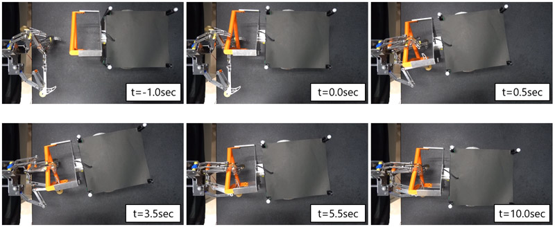
Docking motion of automatic enclosing claw-type mechanism (AECM)
1. Introduction
In recent years, space exploration has advanced, particularly in the field of sample return from celestial bodies, and has seen remarkable progress 1,2,3,4. In the future, sample returns from distant celestial bodies such as Mars 5 and Phobos 6 are planned. To develop future deep-space sample returns, it is essential to improve the mission flexibility and reduce risk. Landing on a celestial body carries the risk of damaging the spacecraft. For example, JAXA’s Hayabusa2 mission made multiple touchdowns on the surface of an asteroid and collected samples from multiple locations. However, the second and subsequent touchdowns risked the loss of previously collected samples if the spacecraft is damaged because of failure 7. Furthermore, in the case of a sample returning from a celestial body with strong gravity, the weight of the spacecraft launched from the celestial body should be minimized from the fuel perspective. In NASA’s and ESA’s Mars Sample Return mission, only capsules containing soil samples are launched from the surface of Mars, and an orbiter captures them 8.
To improve mission flexibility and reduce the risks facing deep-space missions, JAXA is promoting the deep-space orbital transfer vehicle concept 9. This concept aims to make transportation and resupply more efficient by separating spacecraft that perform interorbital transportation from those that perform exploration. Furthermore, JAXA is considering applying this concept to sample returns from deep space 10. The spacecraft system consists of a parent spacecraft that travels between the earth and the target celestial body, and a child spacecraft that lands on the target celestial body. The child spacecraft method protects the parent spacecraft from landing and sampling.
Docking of the parent and child spacecrafts is required to pass samples from the child to the parent. Owing to limited resources, the docking mechanism of deep-space explorers must be lightweight and compact, and cannot be equipped with a large number of sensors and actuators. Furthermore, owing to the length of time required for communicating with the Earth, it is difficult to provide precise guidance based on monitoring and commands from ground stations. Therefore, the docking mechanism must be autonomous and tolerant of errors in the position and attitude during docking.
Conventional docking mechanisms for unmanned spacecraft include the probe and drogue system used by the Progress spacecraft 11, the claw-type system used by ETS-VII 12, and Orbital Express 13. The former has high alignment accuracy and allows for the internal movement of supplies; however, it requires high navigation guidance control accuracy because it is necessary to perform maneuvers that constantly press the probe against the cone during docking, and the mechanism is large. The latter, on the other hand, is relatively compact and has high positional error tolerance; however, it requires the spacecraft to come to a relative stop within the docking range. Boesso and Francesconi 14 and Branz et al. 15 have proposed docking mechanisms for microsatellites based on the probe and drogue method. Although small and lightweight, they were designed for precise guidance of spacecraft. Zhang et al. have proposed a new claw-type capture mechanism (CTCM) that can tolerate large positional errors 16. However, this requires precise sensing of relative positions and appropriate control of the claws. As an alternative method, the latching end effector (LEE) used in the shuttle remote manipulator system (SRMS) and space station remote manipulator system (SSRMS), can be cited as an established object capture mechanism. However, these also require the target to remain within a graspable range for at least 30 s 17.
This study proposes a novel claw-type docking mechanism called automatic enclosing claw-type mechanism (AECM) for deep-space explorers. This mechanism tolerates large positional errors and does not require relative stopping within the docking range. Using a spring mechanism, docking can be completed immediately after the initial contact between spacecrafts without electrical sensing or feedback. Table 1 shows a comparison of claw-type docking mechanisms.
2. Requirements for Docking Mechanism
2.1. Assumed Spacecraft
In this study, we assumed the deep-space explorer system shown in Fig. 1. The spacecraft consists of a parent and child. The parent spacecraft provides transportation between the target celestial body and the Earth, and the child spacecraft performs touchdown and sampling on the surface of the celestial body. The parent and child spacecrafts have a wet weight of 2,000 kg and 100 kg, respectively. Each spacecraft is equipped with a paired docking mechanism. The docking mechanism consists of an active side with an actuator and a passive side with no moving parts. In this study, “docking” is defined as the mechanical coupling and fixation that enables subsequent maneuvers and other umbilical connections.
Table 1. Comparison of claw-type docking mechanism.
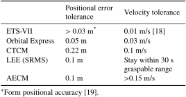
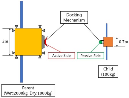
Fig. 1. Concept of the assumed spacecraft.
2.2. Docking Sequence
The concept of the parent-child spacecraft docking sequence assumed in this study is shown in Fig. 2. First, the parent spacecraft approaches the child spacecraft via guidance control using thrusters. After approaching the specified relative distance threshold, the thruster is stopped, and the approach continues by drift motion with relative velocity. Eventually, the active and passive mechanisms make contact, triggering the casing. The active mechanism is driven to complete the alignment correction and six-degree-of-freedom (6-DOF) constraint. Because the active and passive mechanisms are not required to stop relative to each other in the vicinity of the child, the effects of attitude distortions, caused by thruster backfiring, need not be considered.
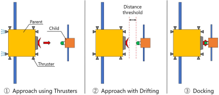
Fig. 2. Docking sequence.
2.3. Requirements for Docking Mechanism
To realize the above docking sequence, the following must be satisfied:
-
Tolerance for relative position and orientation errors during docking.
-
Tolerance of relative velocity and angular velocity error during docking.
-
Avoidance of pushing each other away due to contact forces.
-
Continuous 6-DOF constraint in a defined posture.
-
Release at a specified velocity and angular velocity.
-
Repeatability of docking motion.
-
Preventing the docking mechanism from working at the wrong time.
-
Materials and mechanisms capable of operating in space environment.
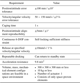
Requirements 1 and 2 are the error tolerances for the relative motion. Deep-space missions require fully autonomous docking. The accuracy of the relative motion control during docking is expected to be low because of the limited number of onboard sensors owing to resource constraints. Requirement 3 is required to ensure docking certainty. Because zero relative motion is not expected, nonnegligible contact forces are anticipated. Additionally, because real-time monitoring operations are not possible in deep space, recovery from docking failure is extremely difficult. In this case, the initial contact force causes them to separate from each other before docking is complete which must be prevented. Requirements 4–8 are general ones for docking mechanisms. Table 2 lists the numerical targets determined by applying these requirements to the spacecraft considered by JAXA 10.
Table 2. Requirements for the docking mechanism.
3. Design of the Docking Mechanism
In this study, we developed a docking mechanism that satisfies the above requirements using claws and springs. This mechanism was inspired by the low contact force grasping hand (LCFH) previously developed by the authors for grasping space debris 20,21. LCFH is a claw-type link mechanism designed to grasp the truss structure of space debris. It is compact, lightweight, and can tolerate a certain degree of relative positional error during contact. However, it lacks functionality as a docking mechanism, because it cannot constrain the two degrees of freedom of the truss axial displacement and rotation around the axis.
This study proposes a docking mechanism consisting of a three-claw mechanism and a dedicated triangular grapple fixture that provides symmetry and 6-DOF constraints on the docking posture. Fig. 3 shows a conceptual diagram of the docking mechanism. Hereafter, the active mechanism, which is the three-claw link mechanism, will be called the AECM, and the passive mechanism, a cylindrical structure arranged in the form of an equilateral triangle, will be called the grapple fixture (GF).
As shown in Fig. 4, the AECM comprises three sets of grasping claws symmetrically spaced \(120°\) apart along the \(x\)-axis. The AECM consists of a claw part that grips the GF, and a drive part that drives it using a motor and gears. The link configuration of the claw consists of four-node links symmetrically arranged in three directions, a central link connecting them, and a drive unit, for a total of 14 links. As shown in Fig. 5, the four-link configuration consists of Link 1, which is driven by the drive unit, and Links 2–4, which are connected using free-rotating joints. The fixed link that is part of the drive unit is Link 0, and the central link that connects Link 4 in each direction is Link 5. The joint connecting Link \((n-1)\) and Link \(n\) is defined as Joint \(n\), and the joint angle between the positive direction of the \(z\)-axis and Link \(n\) is defined as \(\theta_n\).
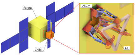
Fig. 3. Concept diagram of docking mechanism.
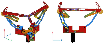
Fig. 4. Overview of AECM.
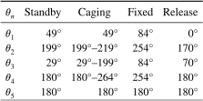
The AECM has four operating states, as illustrated in Fig. 6. The “standby state” is as shown in Fig. 6(a), where \(\theta_{4} = \theta_{5} = 180°\), the claw part is open and waiting for contact with the GF. In this state, when it comes into contact with the GF, the contact force closes the claw, and it immediately transitions to the “caging state” shown in Fig. 6(b). The transition mechanism from the standby to the caging state is described in the following subsection. In the caging state, the GF is enclosed by the claws that are kept closed by a spring attached around Joint 5 so that the child spacecraft cannot escape. By driving Link 1 forward and tightening the GF, it transitions to the “fixed state” shown in Fig. 6(c). During the tightening process, alignment compensation is performed using the geometric shapes of the three pairs of Link 1 and the GFs. Once the fixed state is reached, the GFs are geometrically constrained to 6 DOFs. By driving Link 1 in reverse, the claw is opened, resulting in the “release state” shown in Fig. 6(d). In this process, Link 5 is displaced in the forward \(x\)-axis direction at the same time as the claw is opened to return to the state \(\theta_{4} = \theta_{5} = 180°\), and the GF is pushed out and released using this motion. Subsequently, it is possible to return to the standby state by driving Link 1 forward.
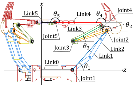
Fig. 5. Definition of links and joints.
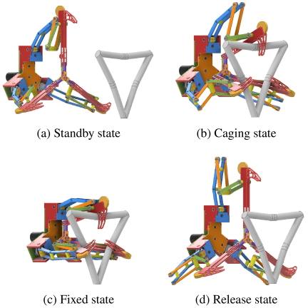
Fig. 6. Operation states of AECM.
3.1. Working Principle of the Transition from the Standby State to the Caging State
The transition sequence from the standby state to the caging state is illustrated in Fig. 7. Tensile springs are attached to Links 4 and 5, and torque \(T_s\) is applied around Joint 5 in the direction of opening of the claw in the standby state, as shown in Fig. 7(a). Let \(l_1\) and \(l_2\) be the distances between Joint 5 and the spring attachment positions of Links 4 and 5, respectively, and let the spring attachment angle \(\theta_s\) be \(\theta_{s} = \theta_{s0}\) in the standby state, as shown in the figure. The spring length \(l_s\) and spring force \(F_s\) produced are
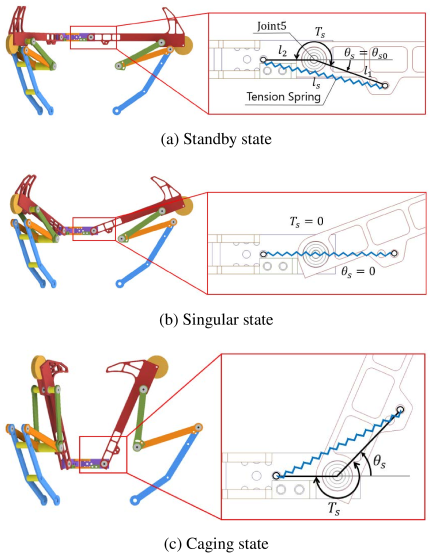
Fig. 7. Transition from the standby state to the caging state.
In the singularity state shown in Fig. 7(b), \(T_s=0\). When the claw closes further, the positive and negative values of \(T_s\) are reversed, and the claw is closed by the spring torque to reach the caging state that encloses the GF, as shown in Fig. 7(c). The energy required for transition from the standby state to the singularity state is given by Eq. (4).
3.2. Design of AECM and GF
3.2.1. Positional Error Tolerance Design
The dimensions of the AECM and GF are shown in Fig. 8. To perform caging, it is necessary for the GF to make contact with Link 4 or Link 5 (excluding the tip of the claw) at the initial contact and for the GF to remain within the area traced by the tip of the claw until caging is complete. The geometric dimensions of the AECM link and GF determine the allowable position and posture errors at the initial contact. Here, considering the worst-case conditions for positional error at the initial contact, the dimensional constraints required to complete caging under two conditions are described: when the maximum positional error is applied in the positive \(z\)-direction, and when the maximum positional error is applied in the positive \(y\)-direction.
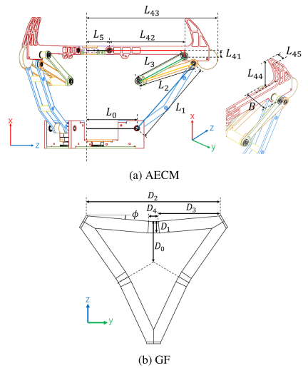
Fig. 8. Definitions of the dimensions.
Assuming that the maximum position error \(P_E\) is in the \(+z\)-axis direction, to prevent the GF from contacting the tip of the claw in the \(+z\)-axis direction, it is necessary to satisfy the following condition:
3.2.2. Friction Tolerance Design
During the transition from the caging state to the fixed state, if the frictional force between contact Link 4 and the GF is large, the GF cannot return to its original fixed position and it cannot be fixed in the correct position in the fixed state. The geometric relationship between Links 4 and 5, and the GF, as well as the forces acting on the GF, are shown in Fig. 9. Distance \(l\) from Joint 5 to the GF contact position satisfies the condition \(0 \leq l \leq L_{42}\). Eq. (10) is derived from the geometric relationship of the center position of the GF cross section.
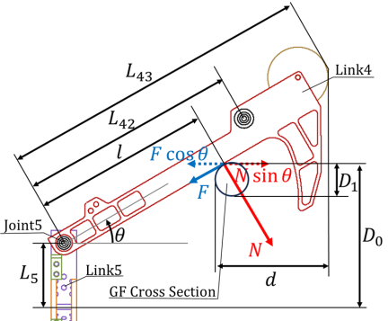
Fig. 9. Geometric relationship between contact link and GF.
3.2.3. Entry Distance Design
Consider the entry distance \(d\) of Link 4 relative to the GF in Fig. 9. It is necessary to set a sufficient distance between the GF and the surface of the child spacecraft such that Link 4 does not come in contact with the the body of the child spacecraft. The entry distance \(d\) is expressed as follows:
3.2.4. Escape Prevention Design
The claw of Link 4 encloses the GF during caging and prevents it from escaping. In the caging state, the GF can move freely within the caging area enclosed by Link 4, and it is necessary to prevent the claws from opening because of the contact force when the GF comes into contact with Link 4 again. Fig. 10 shows the force and torque generated when the GF comes into contact with the claw in the caging state. Owing to the shape of this claw, when the GF comes into contact with the claw, torque \(T\) around Joint 5 is generated in the direction of closing of the claw.
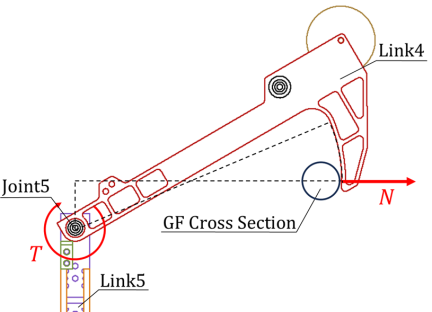
Fig. 10. Contact force and joint torque in caging state.
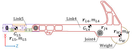
Fig. 11. Relationship between the centers of gravity of Links 4 and 5.
3.2.5. Preventing Unintended Movements Caused by Inertial Forces
The proposed mechanism automatically initiates the caging action based on the contact force between Link 4 and the GF. However, an inertial force also acts on Link 4 owing to the acceleration caused by the maneuvers of the spacecraft. This unintended transition to a caging state owing to the inertial force can be prevented by adjusting the center of gravity position of Link 4. This mechanism is designed such that a weight can be attached to the tip of Link 4 to adjust the center of gravity of the link. The relationship between the centers of gravity of Links 4 and 5, and their weights is shown in Fig. 11. Let the centers of gravity be \(G_{L4}\), \(G_{L5}\), and \(G_W\), respectively, and let the position vectors of the centers of gravity be \(\boldsymbol{r}_{L4}\), \(\boldsymbol{r}_{L5}\), and \(\boldsymbol{r}_W\), respectively. Let the masses be \(m_{L4}\), \(m_{L5}\), and \(m_W\), respectively. The position vector of Joint 4 is denoted by \(\boldsymbol{r}_{J4}\). In this case, \(\boldsymbol{r}_W\) and \(m_W\) must satisfy the following equation:
3.3. Design of Driving Unit in AECM
The fixed state is achieved by closing Link 1 and locking the claw in the caging state. The proposed mechanism has a drive system that drives three Link 1s simultaneously using a single motor. Fig. 12 shows the configuration of the drive unit. Force is transmitted from a single motor to each link via the three gears. In addition, a worm gear is used in the final gear to prevent backdrive.
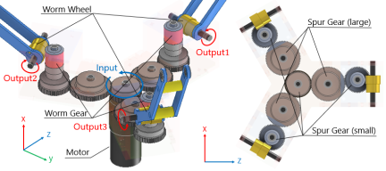
Fig. 12. Drive unit configuration.
3.4. Prototype Specifications
Based on this theory, a prototype was designed. Its appearance is presented in Fig. 13. The dimensions and mass of the AECM are \(210 \times 180 \times 310\) mm and 2.1 kg, respectively, and those of the GF are \(270 \times 230 \times 145\) mm and 0.6 kg, respectively. The parameters for each link are listed in Tables 3 and 4. The joint angles for each state are listed in Table 5.
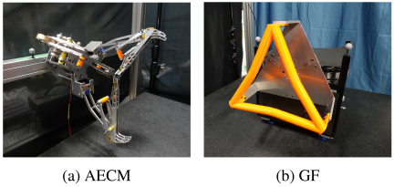
Fig. 13. Appearance of the docking mechanism.
Table 3. Size of AECM.
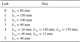
Table 4. Size of GF.
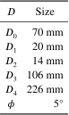
Table 5. Joint angle for each state.
4. Evaluation
4.1. Allowable Positional Error Analysis
To determine the acceptable position and attitude errors of the prototype at the initial contact, an acceptable error analysis is conducted. The conditions for the establishment of caging are as follows:
-
At the initial contact point, the GF is located inside the AECM claw tip in the \(yz\)-plane.
-
Until caging is achieved, the GF is located within the AECM claw tip trajectory in the \(xz\)-plane.
The analysis results for Condition 1 are shown in Fig. 14. The light-blue circular area represents the existence area of the claw tip when there is a position error, and the green area represents the error tolerance area calculated from the GF position. In other words, Condition 1 is satisfied when the light blue area fits within the green area. When the position error \(P_{E} = 100\) mm and \(y\)-axis attitude error \(\theta_{E_y} = 10°\) are set, the required values are within the allowable limit. However, when the \(x\)-axis attitude error is applied, the maximum allowable value is \(\theta_{E_x} = 9°\).
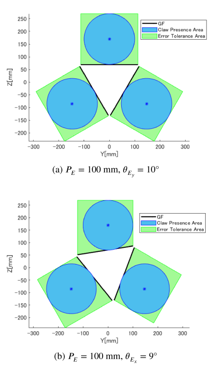
Fig. 14. Error tolerance analysis for Condition 1.
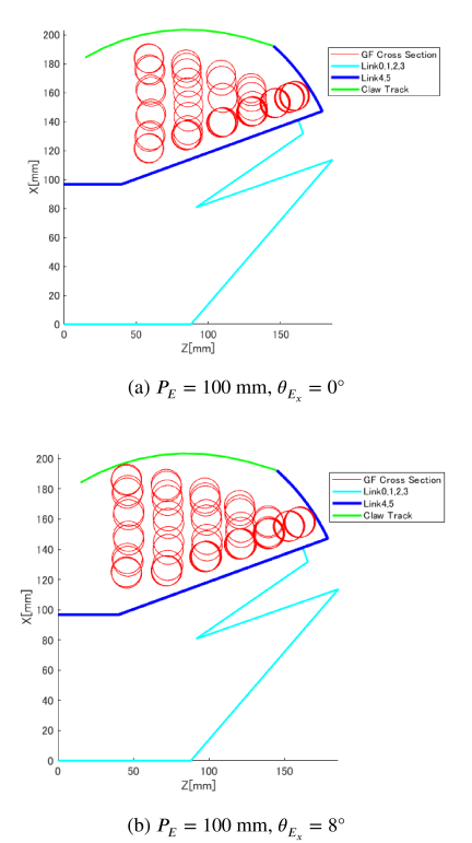
Fig. 15. Error tolerance analysis for Condition 2.
The analysis results for Condition 2 are shown in Fig. 15. Considering the worst-case conditions, the maximum position and attitude errors of \(P_{E}=100\) mm and \(\theta_{E_{yz}} = 10°\), respectively, are fixed. Considering symmetry, we focus on only one claw link and indicate the position of the GF cross section at the singular state, when the direction of the position and attitude errors vary, with red circles in Fig. 7(b). Condition 2 is satisfied if all of these GF cross sections exist within the area inside the claw trajectory represented by the green line. This condition is satisfied when there is no attitude error around the \(x\)-axis; however, when an error is applied, \(\theta_{E_x} = 8°\) is the maximum allowable value.
4.2. Experimental Verification
4.2.1. Experimental Setup
To evaluate the performance of the prototype, docking experiments were conducted in a microgravity emulation environment using an air-floating device. The experimental configuration is illustrated in Fig. 16. The AECM side was fixed to an aluminum frame and the GF was attached to the air-floating device. A 3D motion tracker was used to evaluate the behavior of the air-floating device. Although the inertia of this air-floating device (17.5 kg) is smaller than that of an actual child spacecraft (100 kg), a more radical motion results in conditions that are more severe than the actual conditions. Because air-floating experiments are limited to flat surfaces, considering the symmetry of the mechanism, the orientation of the AECM and GF around the \(x\)-axis was changed to two configurations that represent the worst conditions for positional error, and the experiments were conducted. The configurations of this mechanism are illustrated in Fig. 17. Hereafter, the orientations are referred to as Config 1 and Config 2.
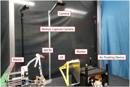
Fig. 16. Experiment configuration.
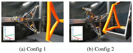
Fig. 17. Experimental configurations.
4.2.2. Caging and Fixation
The air-floating device was given an initial velocity to make contact with the GF and AECM at various positions and angles, and the caging and fixation were confirmed. Fig. 18 shows the behavior of the docking operation when the position offset is 100 mm and the initial velocity is 150 mm/s. The history of the relative position, angle, velocity, and angular velocity of the AECM and GF, with the initial contact set at 0 s, is shown in Fig. 19. The AECM immediately encloses the GF after the initial contact and completes caging within 0.5 s. Subsequently, at approximately 3.5 s, it begins transitioning from the caging state to the fixed state, and an alignment correction is performed. At 10 s, it completes the fixed operation and achieves fixation with a position error of less than \(\pm 5\) mm and an attitude error of less than \(\pm 1°\).
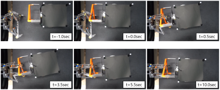
Fig. 18. Motion of the docking.
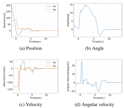
Fig. 19. Error tolerance experiment result.
The docking results for various positions and attitude errors at the initial contact are shown in Fig. 20. The horizontal axis represents the position error, and the vertical axis represents the attitude error. Successful docking is indicated by blue dots, and failed docking is indicated by orange dots. The dotted line represents the boundary between the required values. All the areas inside the dotted lines suggest success, thus meeting the requirements. Two-dimensional docking experiments partially verified the actual three-dimensional docking results. Because the caging itself is completed immediately after the initial contact, the changes in the target’s position and orientation before and after caging are very small, and it is expected that there will be no significant change in the three-dimensional experiments. However, regarding fixation, further verification of three-dimensional motion is necessary to determine the extent of change in the target orientation.
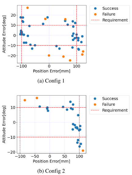
Fig. 20. Caging experiment result.
4.2.3. Minimum Contact Velocity
The lower limit of the initial contact velocity for caging was verified. According to Eq. (7), when the mass of the air-floating device is \(M_{C} = 17.5\) kg, and the dissipated energy is \(E_{D} = 0\) J, the required contact velocity is \(v_{C} = 45\) mm/s. When the mass of a child spacecraft is \(M_{C} = 100\) kg, the required velocity can be converted to \(v_{C} > 18.7\) mm/s. This threshold value and the success or failure of the caging were confirmed experimentally. The relative position and velocity histories for \(v_{C} \simeq 50\) mm/s and \(v_{C} \simeq 40\) mm/s are shown in Figs. 21 and 22, respectively. When \(v_{C} \simeq 50\) mm/s, caging is successful, and the subsequent fixation operation is completed normally. However, when \(v_{C} \simeq 40\) mm/s, the air floating device rebounded after initial contact and caging did not occur. Therefore, the lower limit of the velocity calculated using Eq. (7) is appropriate.
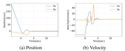
Fig. 21. Lower speed limit experiment (\(v_{C} \simeq 50\) mm/s).
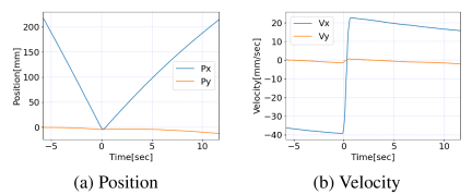
Fig. 22. Lower speed limit experiment (\(v_{C} \simeq 40\) mm/s).
4.2.4. Acceleration Tolerance and Release Operation
Figure 23 shows the transition of the AECM from the fixed state to the release state and then to the standby state. It is possible to return to the standby state by opening and closing Link 1. Although a gravitational acceleration of 1 G acts on Link 4, the standby state is maintained without being affected.
We also verified the release of the GF from a fixed state. Fig. 24 shows the motion of the release operation. Fig. 25 shows the history of the relative position, angle, velocity, and angular velocity with the start of the release operation set to 0 s. Immediately after the operation began at 0 s, the attitude of the air-floating device was disturbed, and the GF was pulled toward the AECM side and then released when pushed back by the claw. The release was completed in approximately 5 s, and the angular velocity error exceeded 1°/s, which did not meet the requirements. To suppress this rotational motion, it is necessary to improve the operation by providing a guide shape or other mechanisms.
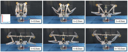
Fig. 23. Transition from fixed state to standby state.
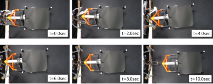
Fig. 24. Motion of the release.
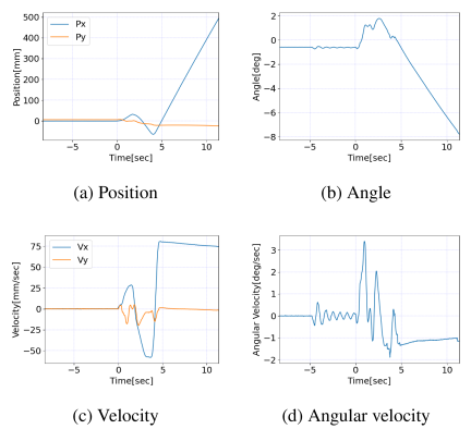
Fig. 25. Release experiment result.
5. Conclusion
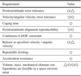
In this study, we propose a mechanism that combines AECM and GF as a docking mechanism that can be installed on deep-space explorers. The requirements for the docking mechanism to perform the assumed docking sequences are summarized. The design of a mechanism that satisfies these requirements is clarified, and performance evaluation experiments are conducted on a prototype to demonstrate the validity of the design. The requirement fulfillment status in this study is presented in Table 6. The remaining issues are improving the release operation and evaluating the performance of the mechanism in a three-dimensional space. With regard to the latter, we are in the process of developing a three-dimensional numerical simulation model and a 6-DOF motion hybrid simulator using robotic arms.
The proposed docking system which is capable of accommodating high-velocity and positional errors, holds potential for development not only for spacecraft but also as a general robotic docking mechanism.
Table 6. Requirement fulfillment.
Acknowledgments
This work was conducted as a joint research project between JAXA and Institute of Science Tokyo entitled “Development of a docking mechanism suitable for deep space missions.”
- [1] S. Abe et al., “Mass and local topography measurements of Itokawa by Hayabusa,” Science, Vol.312, No.5778, pp. 1344-1347, 2006. https://doi.org/10.1126/science.1126272
- [2] T. Yada et al., “Preliminary analysis of the Hayabusa2 samples returned from C-type asteroid Ryugu,” Nat. Astron., Vol.6, No.2, pp. 214-220, 2022. https://doi.org/10.1038/s41550-021-01550-6
- [3] D. S. Leuretta et al., “OSIRIS-REx: Sample return from asteroid (101955) Bennu,” Space Sci. Rev., Vol.212, Nos.1-2, pp. 925-884, 2017. https://doi.org/10.1007/s11214-017-0405-1
- [4] Z. Cui et al., “A sample of the Moon’s far side retrieved by Chang’e-6 contains 2.83-billion-year-old basalt,” Science, Vol.386, No.6728, pp. 1395-1399, 2024. https://doi.org/10.1126/science.adt1093
- [5] B. K. Muirhead, A. K. Nicholas, J. Umland, O. Sutherland, and S. Vijendran, “Mars sample return campaign concept status,” Acta Astronaut., Vol.176, pp. 131-138, 2020. https://doi.org/10.1016/j.actaastro.2020.06.026
- [6] K. Kuramoto et al., “Martian moons exploration MMX: Sample return mission to Phobos elucidating formation processes of habitable planets,” Earth Planets Space, Vol.74, Article No.12, 2022. https://doi.org/10.1186/s40623-021-01545-7
- [7] Y. Tsuda, T. Saiki, F. Terui, S. Nakazawa, M. Yoshikawa, and S. Watanabe, “Hayabusa2 mission status: Landing, roving and cratering on asteroid Ryugu,” Acta Astronaut., Vol.171, pp. 42-54, 2020. https://doi.org/10.1016/j.actaastro.2020.02.035
- [8] B. Sarli et al., “NASA’s capture, containment, and return system: Bringing Mars samples to Earth,” Acta Astronaut., Vol.223, pp. 270-303, 2024. https://doi.org/10.1016/j.actaastro.2024.05.048
- [9] Y. Takei et al., “The deep space orbital transfer vehicle inspired by the Hayabusa2 technology,” J. Evol. Space Act., Vol.1, Article No.40, 2023. https://doi.org/10.57350/jesa.40
- [10] T. Saiki et al., “Mission concept of Japanese comet sample return exploration in the 2030s,” Acta Astronaut., Vol.235, pp. 120-128, 2025. https://doi.org/10.1016/j.actaastro.2025.05.048, 2025.
- [11] J. Cook, V. Aksamentov, T. Hoffman, and W. Bruner, “ISS interface mechanisms and their heritage,” AIAA SPACE 2011 Conf. Expo., 2011. https://doi.org/10.2514/6.2011-7150
- [12] M. Kunugi, H. Koyama, T. Okanuma, T. Nakamura, M. Mokuno, I. Kawano, H. Horiguchi, and K. Kibe, “Guidance, navigation and control system in Engineering Test Satellite VII rendez-vous and docking experiment,” Autom. Control Aerosp. 1994, pp. 303-308, 1995. https://doi.org/10.1016/B978-0-08-042238-1.50051-3
- [13] S. Christiansen and T. Nilson, “Docking system mechanism utilized on orbital express program,” Proc. 39th Aerosp. Mech. Symp., pp. 207-220, 2008.
- [14] A. Boesso and A. Francesconi, “ARCADE small-scale docking mechanism for micro-satellites,” Acta Astronaut., Vol.86, pp. 77-87, 2013. https://doi.org/10.1016/j.actaastro.2013.01.006
- [15] F. Branz, L. Olivieri, F. Sansone, and A. Francesconi, “Miniature docking mechanism for CubeSats,” Acta Astronaut., Vol.176, pp. 510-519, 2020. https://doi.org/10.1016/j.actaastro.2020.06.042
- [16] X. Zhang, Q. Liu, X. Ma, W. Gong, and W. Wang, “Design and analysis of a large tolerance docking mechanism,” Acta Astronaut., Vol.221, pp. 121-141, 2024. https://doi.org/10.1016/j.actaastro.2024.05.014
- [17] R. G. Daniell and S. S. Sachdev, “The design and development of an end effector for the shuttle remote manipulator system,” Proc. 16th Aerosp. Mech. Symp., pp. 45-61, 1982.
- [18] N. Kubota, R. Sakata, M. Mokuno, and I. Kawano, “Docking mechanisms for ETS-VII rendezvous-docking,” J. Soc. Instrum. Control Eng., Vol.38, No.11, pp. 691-694, 1999 (in Japanese). https://doi.org/https://doi.org/10.11499/sicejl1962.38.691
- [19] M. Mokuno, I. Kawano, and T. Suzuki, “In-orbit demonstration of rendezvous laser radar for unmanned autonomous rendezvous docking,” IEEE Trans. Aerosp. Electron. Syst., Vol.40, No.2, pp. 617-626, 2004. https://doi.org/10.1109/TAES.2004.1310009
- [20] K. Taga, H. Nakanishi, and M. Oda, “Development of a retractable twine gripper for debris-capture,” 31st Int. Symp. Space Technol. Sci., 2017.
- [a] N. Kawaguchi and H. Nakanishi, “Development of a truss structure grasping end-effector for on-orbit servicing,” 33rd Int. Symp. Space Technol. Sci., 2022.
This article is published under a Creative Commons Attribution-NoDerivatives 4.0 Internationa License.