
Paper:
A Lightweight Long-Reach Manipulator with Highly Backdrivable Actuators for Outdoor Terrain-Contact Tasks: ParaLambda
Atsushi Kakogawa
 and Ryutaro Fukunaga
Department of Robotics, Ritsumeikan University
1-1-1 Nojihigashi, Kusatsu, Shiga 525-8577, Japan

This study proposes a lightweight long-reach outdoor robot arm equipped with highly backdrivable actuators, named “ParaLambda,” for terrain-contact tasks on uneven ground. The robot employs a parallel-link structure and carbon-fiber reinforced polymer links to achieve both long-reach and lightweight construction, while low-gain PD control with quasi-direct-drive actuators provides passive compliance against external forces without requiring additional force/torque sensors. As a representative application, outdoor mowing work in rough terrain is considered. The developed prototype has a maximum reach of 4.15 m and an arm weight of 8.35 kg. To evaluate the feasibility of the proposed concept, preliminary indoor experiments and outdoor grass-cutting experiments were conducted. The experimental results confirmed stable repetitive motion, terrain-contact capability through passive compliance, and practical outdoor mowing operation while maintaining joint torque within the allowable actuator range. These results demonstrate the feasibility of lightweight compliant long-reach manipulators for outdoor terrain-contact applications.
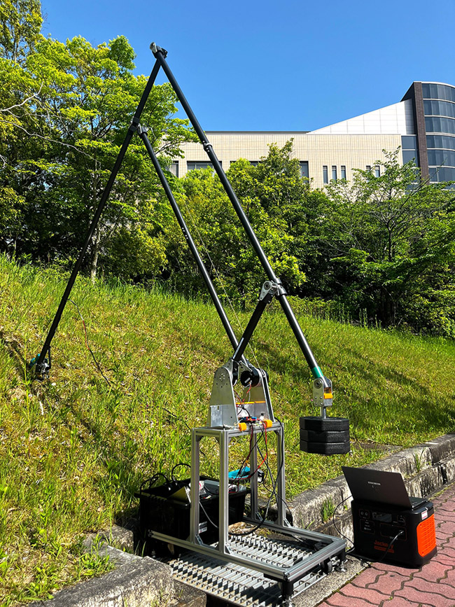
A lightweight long-reach outdoor robot arm for terrain-contact tasks
1. Introduction
Reaching distant locations to pick up objects or perform tasks has traditionally presented a challenging problem for robot manipulators. Several lightweight and long-reach manipulators have, therefore, been proposed in recent years, including compliant manipulators and lightweight balloon-body manipulators 1,2. This problem does not arise when a mobile robot can crawl across the ground or a flying robot, such as a drone (multi-copter), can travel over obstacles to reach the target location. However, in environments with highly disordered ground conditions, such as natural landscapes, mobile robots are not always applicable. Furthermore, flying robots face significant constraints, such as payload capacity and continuous operation time due to battery limitations. In such cases, a robot arm firmly anchored on the ground, with only its arm suspended in the air, moving its end-effector over long distances to perform tasks, is considered an effective approach.
Generally, for articulated-type robot arms, such as those used in industrial robots, extending the reach (here defined as the maximum horizontal distance that the end-effector can travel from the robot base) can be achieved simply by lengthening the links. However, longer links introduce two main problems. First, increased mass demands greater output from the actuators supporting the links. The second is that increased link deflection necessitates the use of highly rigid materials to maintain end-effector positioning accuracy. Consequently, merely extending the reach is not feasible. Instead, the robot arm must be constructed with links that are not only long, but also thick and heavy, made from rigid castings with large cross-sections. Therefore, large, high-power motors and high-reduction-ratio gearboxes are used for the joint actuators. For example, even when the target task is simply “pick-and-place” of lightweight objects weighing only several tens of grams, extending the reach generally requires a large and heavy robot structure to maintain sufficient rigidity and positioning accuracy. In order to support its increased weight and minimize deflection, the robot arm inevitably becomes bulky.
For simple indoor pick-and-place tasks in which only reach extension is needed, such heavy, rigid, long industrial robot arms might suffice a,b. When handling only light objects, however, the robot’s inherent stiffness and weight can become problematic and unsuitable for the following applications:
-
If there is a possibility that the arm may collide with the environment or objects during tasks, the high inertia and rigidity will cause excessive impact force, which is extremely hazardous.
-
In applications in which the robot needs to be moved frequently, it is not only cumbersome but also dangerous. This is particularly noticeable when moving on uneven ground.
Therefore, a long-reach robot arm that can overcome these challenges must be both inherently light and sufficiently flexible to tolerate positional errors.
In this study, a long-reach, lightweight robot arm with a reach of approximately 4 m and an arm weight of approximately 8 kg is proposed, as shown in Fig. 1. The robot arm uses a conventional parallel link mechanism to concentrate all heavy actuators at the base and employs highly backdrivable actuators. Although this robot arm can be used indoors, outdoor weeding work with a brush cutter is assumed to be its final application because its high backdrivability could be useful for physical contact work. Specifically, it targets the removal of weeds growing on cliffs and in hollows, which has been difficult with both manual brush-cutting (in which a person uses a brush cutter as a tool) and self-propelled brush-cutting (in which the brush cutter is integrated with a wheeled or other mobility mechanism).
Lightweight and compliant long-reach manipulators have also been investigated in previous studies. For example, Takata and Endo proposed a coupled tendon-driven long-reach manipulator with dynamics-based control and path-planning methods 3. Furthermore, lightweight musculoskeletal structures using tensegrity mechanisms have also been explored 4. Compared with these approaches, this study focuses on terrain-contact outdoor operation using highly backdrivable actuators and lightweight carbon-fiber reinforced polymer (CFRP) links.
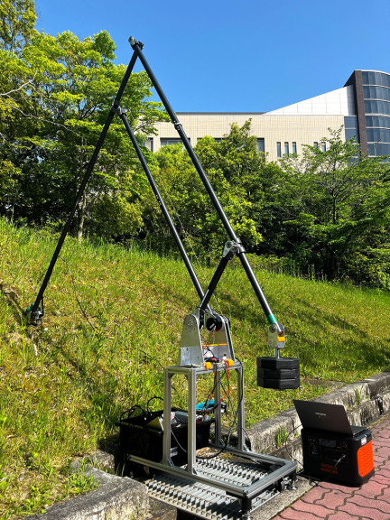
Fig. 1. Overview of the long-reach and lightweight robot arm named “ParaLambda.”
It is worth noting that the objective of this study is not to realize a highly redundant manipulator with many degrees of freedom [5, c], but rather to investigate whether a lightweight and compliant long-reach structure can effectively perform outdoor terrain-contact tasks.
2. Related Works on Weeding Machine
In humid regions, such as Japan, weed cutting operations are conducted in almost all locations for numerous reasons, such as maintaining aesthetics and ensuring safety. These operations range from weeding artificially maintained environments, such as lawns, to clearing unkempt areas where various plants grow haphazardly. In the past, all such work was performed manually. These tasks involve high-speed rotating blades or equivalent equipment, and pose major risks, such as accidents from blade contact, harm to workers or bystanders from flying debris, and vibration-induced white finger syndrome. Moreover, since work primarily occurs in unmanaged outdoor environments, environmental hazards, such as falls, bites from pests, and heatstroke, are also present. To protect workers from these dangers and enable efficient operation, various equipment is now in practical use.
For instance, Husqvarna of Sweden markets the AUTOMOWER series d of robotic lawn mowers. For weeding large, relatively flat areas with tough weeds, such as athletic fields or riverbanks, the Spider series e from the Czech company DVOŘÁK is sometimes used. These products feature an integrated structure combining a self-propulsion unit and rotating cutting blades. Such machines, however, are designed primarily for mowing uniform, low-growing weeds or trimming lawns. They are unsuitable for environments with dense, mixed vegetation or dead leaves on the ground.
For continuous slopes with roads at the top, such as roadside verges or field boundaries, large hydraulic arm mowers are employed. These mount cutting blades on trucks or tractors, which enables continuous mowing while the vehicle moves. An example is the MULAG front mower f sold by the German company MULAG. This is a hydraulic arm-type mower mountable on the front of a truck, and removes weeds on road shoulders while driving. However, due to the large size and weight of the hydraulic arm, large vehicles are required for transport, and operation from well-maintained roads is assumed. Consequently, it is difficult to use on rough terrain, such as muddy areas or narrow roads.
For river embankments and slopes steeper than 45°, equipment exists that suspends the cutting blade from the top of the slope using a wire to perform weeding. Husqvarna Zenoah Co., Ltd.’s KHM400W Belon g uses a similar structure for steep-slope weeding. However, this method carries the risk of the wire becoming entangled in vegetation and cannot be used to straddle depressions, such as ditches. As a consequence, manual weeding remains commonly used for terrain that is inaccessible to conventional equipment, such as obstacles, like fences and waterways, steep slopes, and areas with severe unevenness.
Therefore, this research aims to develop a robot for labor-saving and unmanned weeding operations in the aforementioned terrain. To achieve this, the lightweight and long-reach robot arm “ParaLambda” (Fig. 1) is proposed. The long-reach structure enables the aerial deployment of brush cutters to areas that are difficult to access by land. Furthermore, minimizing weight contributes to high-speed operation, low energy consumption, and high portability. This paper describes the robot’s structure and principles, followed by reports on preliminary indoor experiments and outdoor brush-cutting experiments to evaluate its basic performance and potential utility.
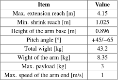
Table 1. Specification of the robot arm “ParaLambda.”
3. Mechanical Design and Control Architecture
Prior to designing the robot arm, the target operational scenario and requisite specifications were defined based on outdoor mowing tasks in rough terrain. The target environment includes slopes, hollows, narrow spaces, and areas around obstacles where conventional mobile mowing systems have difficulty accessing. The primary design requirements are: (1) reach exceeding 4 m; (2) lightweight structure enabling manual transportation; (3) passive compliance for terrain-contact tasks without force sensors; (4) payload capacity sufficient for commercially available brush-cutter heads; and (5) arm end velocity around 1 m/s for practical mowing operation.
The target reach of approximately 4 m was determined based on the assumed outdoor mowing scenario, in which the robot arm accesses vegetation beyond roadside obstacles, such as fences, hedges, and drainage structures while remaining positioned on stable ground. The maximum target arm end speed was set to approximately 1 m/s based on the typical sweeping speed observed during manual brush cutter operation. The actuator torque was selected such that the required joint torque remained within the rated torque range even when supporting the approximately 8 kg arm structure together with the approximately 1 kg brush-cutter head at extended configurations.
Our developed robot arm, “ParaLambda,” is composed of a well-known parallel link mechanism, which enables easy weight reduction of the link sections since the actuators can be concentrated at the base. The performance of the robot arm is given in Table 1. The extension length is measured from the actuator axis as the origin to the cutting blade rotation axis. The pitch angle is the angle formed between a straight line connecting the actuator axis and the hand pitch axis and the horizontal plane. The payload capacity is designed with a margin allowing for up to 3 kg. This design anticipates future applications, such as equipping the robot with more powerful brush cutters featuring metal blades, or repurposing it for other tasks. Although the current prototype is intended to cover a working radius of approximately 4 m, vertical planar movement is only considered. The arm is intended to be mounted on a mobile platform, and this presents a future challenge. This section details the robot’s hardware structure and control architecture.
3.1. Hardware Structure
A similar structure has also been adopted in the landmine detection robot Gryphon-V developed by Freese et al. 6,7. Gryphon-V features a 5-degree-of-freedom robot arm using a parallel link mechanism mounted on the rear of a 4-wheel buggy chassis. A mine detector capable of movement along the pitch and roll axes is connected to the robot arm’s end-effector, while a stereo camera for terrain detection is mounted on the mid-section of the arm. Additionally, a counterweight is attached to the rear end of the arm for balance.
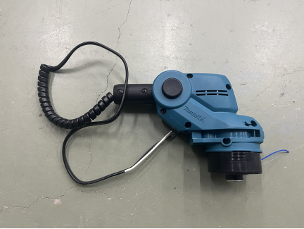
Fig. 2. Mower head module as an end-effector of ParaLambda.
Our robot arm has an aluminum frame base supporting a 3-degree-of-freedom arm with a maximum length of 4 m. The end-effector is designed to mount the head unit of a Makita Corporation brush cutter (MUR193D) h, as shown in Fig. 2. The design allows the arm to extend, travel over obstacles, and deliver this cutting blade to the target location, which allows work in areas where weeding has been problematic with existing devices.
Currently, the end-effector can only move within a vertical two-dimensional plane. However, future improvements are planned that add a rotatable joint at the base, which facilitates movement in three-dimensional space. Furthermore, as this is an early stage of research, a nylon cord was used instead of metal blades due to safety considerations.
A counterweight with a total weight of 10.9 kg is equipped at the rear of the body to balance the robot arm during deployment. This counterweight is designed to be suspended from an axis in a swingable manner. This structure lowers the overall center of gravity of the arm assembly. The torque required for attitude control during pitch maneuvers can be also reduced, and rollover can be prevented.
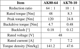
Due to its development objective of weeding tasks, this robot performs tasks involving ground contact in outdoor environments. Therefore, no sensors are installed on the arm end-effector or passive joints, with the aim of reducing failure risk and achieve weight reduction. For actuators, two CubeMars AK80-64 geared brushless DC motors were used to drive the main arm (joints 1 and 2), and one CubeMars AK70-10 geared brushless DC motor was used to drive the end-effector (joint 3). Figs. 3 and 4 show their overview and how they are installed in the arm base. \(\theta_1\) and \(\theta_2\) denote the joint angles in their joint coordinate systems. This is intended to avoid overlap between the two joint angle plots in a single graph. Table 2 lists their specifications.
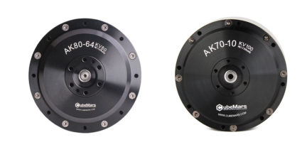
Fig. 3. Overview of the backdrivable actuators: Ak80-64 and AK70-10.
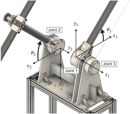
Fig. 4. Actuators installed in the arm base and their coordinate systems to define the rotational angles.
Table 2. Specifications of AK80-64 and AK70-10.
These actuators integrate large-diameter brushless motors, planetary gear reducers, and embedded drive circuit boards while maintaining relatively high backdrivability for torque density. This type of actuator is generally referred to as a quasi-direct-drive (QDD) actuator. In recent years, commercially available QDD actuators with relatively high torque density and backdrivability have become increasingly available. Because of their relatively low reduction ratios, these actuators rely more directly on motor torque generation compared with conventional high-ratio geared actuators.
The high backdrivability of a joint actuator signifies high flexibility against external forces. Originally, gearboxes were often incorporated to achieve a reduction ratio of \(10:1\) or less, as seen in the AK70-10. Recently, however, gearboxes with reduction ratios up to approximately \(100:1\), such as the AK80-64, have also become available. Naturally, as the reduction ratio increases, the backdrive torque also increases.
It is generally well known that the rotor inertia, when converted to the actuator’s output shaft, is proportional to the square of the reduction ratio. QDD motors, although not as low as DD motors, have lower reduction ratios. This allows them to maintain an equivalent low rotor inertia on the output shaft, which enhances the ease with which the rotor shaft rotates in response to external forces applied to the output shaft (backdrivability). This state can be described as high transparency in torque transmission between the actuator’s input and output. This means that the effects of controller feedback gains, such as those in PD control, are likely to be significantly reflected in its behavior. The concept of this research is to drive this actuator using PD control with reduced P-gain, which permits it to function as a pseudo spring-damper system and allows continuous contact with the terrain. Reducing the P-gain, however, decreases joint stiffness of robot arms. When the arm is heavy, this can lead to reduced tracking performance to target values during rapid movements, increased convergence time, and the potential induction of vibration phenomena due to a decrease in the natural frequency.
Therefore, to prevent these issues, it is essential to utilize actuators with high backdrivability to reduce joint stiffness while simultaneously pursuing significant weight reduction of the robot arm itself. ParaLambda employs CFRP pipes with an outer diameter of 40 mm and a wall thickness of 1 mm for each link, which achieves weight reduction while ensuring the necessary strength and stiffness. Additionally, ultra-high strength duralumin components were used for joints and pipe connections throughout the body, and joint shafts were hollowed to further reduce weight. Combining these lightweight design measures with the aforementioned sensor elimination, the design prevents deterioration in end-effector positioning accuracy and tracking performance. However, it is worth noting that this research does not aim to achieve the same rigidity or positioning accuracy as industrial robots. Instead of sacrificing these performance characteristics, priority is given to extending reach and performing tasks involving mechanical contact with the environment.
The current prototype mainly focuses on planar motion in order to investigate the feasibility of lightweight long-reach terrain-contact operation. Out-of-plane stiffness and torsional vibration suppression are left for future work involving three-dimensional motion. As reported in previous literature on compliant long-reach manipulators 6,7, suppression of out-of-plane vibration and oscillation becomes important for pragmatic outdoor deployment.
As mentioned above, a parallel link mechanism is used to control the position of the arm’s end. However, an additional actuator is required to control the pitch attitude of the end-effector. Attaching a heavy actuator to the arm end with its very long links would significantly increase the required joint torque at the base. Therefore, an additional parallel link mechanism was added, and the third actuator for pitch attitude control was placed at the arm base. However, adding a large parallel link mechanism made of CFRP pipes risked significantly increasing the robot’s total weight. For this reason, as shown in Fig. 5, the decision was made to transmit the third actuator’s torque using an antagonistic mechanism with metal wires.
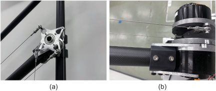
Fig. 5. Antagonistic mechanism driven by joint 3 to control the pitch posture of the arm end.
3.2. Control Architecture
The actuator used in this study incorporates a drive circuit board, as previously described, which enables the transmission and reception of command values and current values via control area network (CAN) or universal asynchronous receiver-transmitter communication protocols. Since outdoor use was anticipated, a CAN BUS was adopted due to its noise immunity, and a communication system using daisy chain connections was constructed. The actuator was driven using a 1500 W-48 V power supply. Moreover, a separate 24 V stabilized power supply was used for the CAN BUS shield drive. Fig. 6 illustrates the control architecture and communication system of ParaLambda. In this system, a host PC transmits desired joint angle commands to actuator nodes through the CAN bus network.
As described in Section 3.1, ParaLambda employs PD control to treat the robot arm body as a pseudo-spring damper system. This design allows continuous contact with the terrain while supporting part of the arm’s weight during mowing operations using reaction forces from the ground. The actuator’s circuit board incorporates a pre-programmed PD control loop and corresponding communication protocol. Therefore, the decision was made to utilize this at the current stage. P-gain and D-gain were set as 500 Nm/rad and 5 Nms/rad, respectively. These gains were experimentally tuned to achieve stable repetitive motion while maintaining sufficient compliance against environmental contact forces. The gains were selected as the minimum values that maintained stable repetitive motion without inducing excessive oscillation. Larger gains increased structural vibration and impact during terrain contact; whereas, smaller gains degraded motion stability and trajectory-tracking performance.
The host PC calculates the desired joint angles from the target end-effector trajectory using inverse kinematics. The calculated joint angle commands are transmitted to each actuator node via CAN communication. Low-level PD position control is executed by the embedded controllers inside of the actuators. Although the communication protocol supports transmission of angle, angular velocity, and torque-related information, only joint angle commands were used in the current implementation. Measured joint angle, angular velocity, and motor current values are fed back from the actuator nodes to the host PC through the CAN bus. The command angles \(\theta _{d1}\) and \(\theta_{d2}\) derived from these inverse kinematics equations are described in Eqs. (1) and (2), respectively. Here, \(x_e\) and \(y_e\) represent the horizontal position and height of the end-effector axis, respectively, when the actuator axis is set as the origin. Furthermore, \(L_1\) and \(L_2\) denote the distances between the shoulder joint and the elbow joint, as well as that between the elbow joint and the tip, respectively, as illustrated in Fig. 7. They are both designed to 2 m.
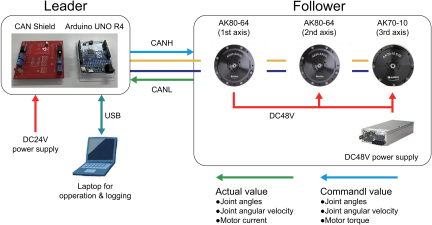
Fig. 6. Control architecture configuration for ParaLambda.
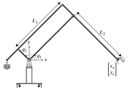
Fig. 7. Geometric definitions of the robot arm in the global coordinate system.
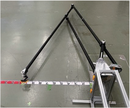
Fig. 8. Experimental setup for the external force measurement.
4. Experiments
To verify the performance of the robot arm designed and constructed in this study, and to confirm the feasibility of terrain-contact operations using backdrivability, preliminary motion experiments were conducted indoors. To replicate real-world operational conditions, the arm’s end-effector was equipped with a brush cutter head (0.85 kg), and a counterweight (10.9 kg) was attached to maintain balance during testing. The weight of this counterweight was set based on the material properties of the CAD model to ensure that the arm could achieve equilibrium.
4.1. Indoor Test for the Verification of Basic Performance
4.1.1. Experiment 1: External Force Measurement for Backdrivability Evaluation
First, the backdrivability of the robot arm end under external forces was evaluated. As shown in Fig. 8, ParaLambda was placed horizontally on the ground to eliminate the effects of gravity, and then pulled using a force gauge attached to the arm end. The \(y\)-coordinate of the arm end position was set to zero, and only the \(x\)-coordinate was moved from 1 m to 3.5 m in 0.5 m increments. The pulling directions were up/down and forward/backward, and the average value of a total of five trials was recorded for each direction.
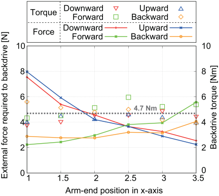
Fig. 9. Measured external forces of the arm end in upward, downward, forward, and backward directions and joint torques calculated by the kinematic model required for backdrive.
As shown in Fig. 7, the absolute angles of the links driven by joints 1 and 2 in the global coordinate system are defined as \(q_1\) and \(q_2\), respectively. In this case, the static relationship between the end-effector force \(\mbox{$\boldsymbol{f}$}\) and the joint torque \(\mbox{$\boldsymbol{\tau}$}\) can be derived from static equilibrium and the Jacobian matrix \(\boldsymbol{J}\) as follows:
Using the inverse kinematics model, \(q_1\) and \(q_2\) are obtained as follows:
Figure 9 plots the resulting external forces of the arm end and joint torques calculated by the kinematic model required for the backdrive in each position and direction. These results indicate that, as there was no significant difference between the upward and downward directions, there was also no marked gap between the forward and backward directions. In the upward/downward direction, the force required for the backdrive decreased as the arm end moved further from the base; whereas, in the forward/backward direction, the opposite result was observed. This occurs because when the arm is extended, the moment-arm becomes longer for forces applied in the upward/downward direction; while, conversely, it becomes shorter for forces in the forward/backward direction.
Similarly, there was no statistically significant difference between the measured backdrive torque and the catalog value of 4.7 Nm. The overall mean torque of the 24 data points was approximately 4.63 Nm, with a standard deviation of 0.56 Nm and a mean absolute error (MAE) of 0.48 Nm.
4.1.2. Experiment 2: Repetitive Motion Test of the Arm End
In this experiment, the arm base was set as the origin, and a sinusoidal reciprocating trajectory with an amplitude of 1 m and a period of 6 s was defined, centered on a point 2 m horizontally ahead. The end-effector trajectory, where \(t\) denotes the elapsed time, is described below:
The velocity \(v_x(t)\) of the end-effector along this trajectory is obtained by differentiating \(x_e(t)\) with respect to time \(t\) as follows:
Figure 10 shows frame-by-frame images of the experiment at 1-second intervals (a) and visualization of the arm end trajectory during the experiment and its measured value (b), while Fig. 11 shows the commanded and measured joint angles together with the measured joint torque estimated from motor current values.
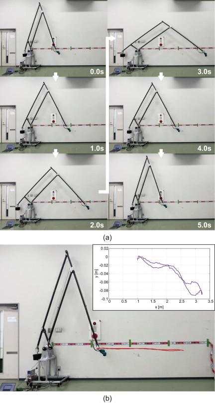
Fig. 10. Frame-by-frame images during the repetitive arm end motion experiment (a) and visualization of the arm end trajectory during the experiment and its measured value (b).
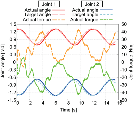
Fig. 11. Commanded and measured joint angles and measured joint torque during repetitive motion in air.
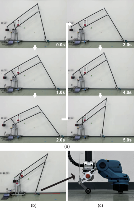
Fig. 12. Frame-by-frame images during repetitive motion with ground contact and without obstacles (a), visualized trajectory (b), and the roller attached to the arm end (c).
In this experiment, to assess the tracking performance of the arm end position, recorded videos were analyzed using Kinovea, a motion analysis software. The analysis utilized the video from the motion experiment, as shown in Fig. 10(b). The arm end pitch axis was selected as the trace target. The arm end’s travel distance in the video was scaled relative to a tape measure affixed to the wall surface to determine the actual travel distance.
The results for the joint angle at the arm base indicate that, while there is no deviation between measured and commanded values during arm extension, during flexion, both the first and second axes show a 0.3-s delay in measured values relative to commanded values. Furthermore, the horizontal end-effector position deviated positively by 0.22 m from the target of 3 m, and a maximum vertical downward deviation of 0.09 m was found. This is thought to be attributable to the inability to correct deviations caused by the links’ own weight and link deflection, resulting from the adoption of PD control to allow for terrain contact. On the other hand, it was found that the maximum arm end speed achieved the intended performance.
4.1.3. Experiment 3: Repetitive Motion Test of the Arm End with Ground Contact and Without Obstacles
Next, a test was conducted in which only the vertical target position was set to \(y=-0.866\) m without altering the horizontal arm end trajectory described in Eq. (6). Due to issues exceeding the arm’s range of motion, unlike Section 4.1.2, the amplitude was reduced by 0.25 m. In this experiment, a sinusoidal reciprocating trajectory with an amplitude of 0.75 m and a period of 6 s was defined, centered on a point 2 m horizontally ahead. Fig. 12 presents frame-by-frame images of the experiment and the visualized arm end trajectory during terrain-contact motion (a), visualized trajectory (b), and the roller attached to the arm end (c). Similar to the previous experiment, the arm end trajectory was analyzed using Kinovea motion analysis software.
This refers to a target motion where the arm end just traces the ground surface. Under this condition, the normal force applied to the arm end from the ground should be zero. However, in reality, due to the PD control without gravity compensation and the low link stiffness of CFRP, the end-effector sags. As a result, the normal force at the arm end is not zero but becomes a large value.
Figure 13 shows the target and actual joint angles and measured joint torque of the first and second axes during the motion with ground contact and without obstacles. This result suggests that, despite being equipped with the roller, contact with the ground caused rolling friction to degrade arm end tracking (particularly timing). As a result, the joint 1 remained nearly stationary, while the joint 2 alone moved the arm end in a manner that caused it to scrape along the ground. The joint 1 corresponds to the long side of the parallel link, while the joint 2 corresponds to the short side. Therefore, this resembles a motion where the joint 1 is fixed and only the joint 2 scrapes the ground.
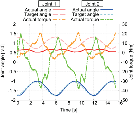
Fig. 13. Commanded and measured joint angles and measured joint torque during repetitive motion with ground contact and without obstacles.
Furthermore, unlike the results for aerial movements (Fig. 11), the joint torques decreased significantly (by up to about half). This is expected to be because the arm end was supported by the normal force from the ground, reducing the joint torque required to support the arm’s weight.
4.1.4. Experiment 4: Repetitive Motion Test of the Arm End with Ground Contact and with an Obstacle
The test was also conducted with a thin obstacle plate (5 mm in height and 100 mm in length) placed on the ground under the same conditions as Section 4.1.3. The geometrical relationship between the robot arm and the ground obstacle is illustrated in Fig. 14. Fig. 15 presents frame-by-frame images of the experiment during terrain-contact motion with the obstacle.
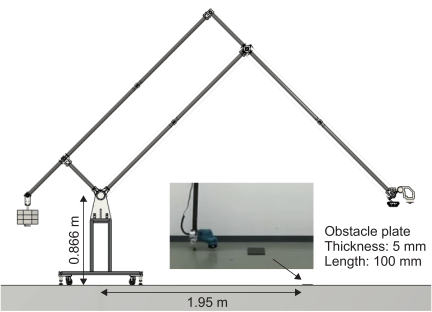
Fig. 14. Geometrical relationship between the robot arm and a ground obstacle.
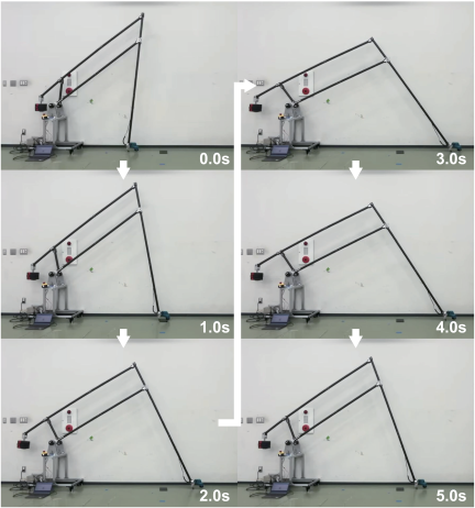
Fig. 15. Frame-by-frame images during repetitive motion with ground contact and an obstacle.
Experiments demonstrated that the arm end can perform reciprocating motion without becoming stuck while navigating over an obstacle. Fig. 16 presents the target and actual joint angles and measured joint torque of the first and second axes during the motion with ground contact and with an obstacle. This graph shows results that are very similar to those given in the aforementioned Fig. 13.
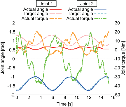
Fig. 16. Target and actual joint angles and measured joint torque of the first and second axes during the motion with ground contact and with an obstacle.
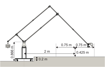
Fig. 17. Geometrical relationship between the robot arm and the flat ground during the outdoor experiment.
Assuming that shape-adaptive motion is achieved through PD control, irregular changes in the joint angle should appear inherently. However, they did not appear in practice. This is thought to be because the deflection of the CFRP links dominates the shape-adaptive motion more than the joint flexibility provided by PD control.
On the other hand, unusual peaks and troughs in torque appeared around 1.5 s, 3 s, 7.5 s, 9 s, 13.5 s, and 15 s at both joints. This implies that the reaction force received from the obstacle when the arm end extends from near-to-far is reflected in the joint torque.
Although tracking delay and arm end sag were observed due to low stiffness and the inaccuracy in the gravity compensation, the measured torque remained within the actuator’s allowable range throughout the experiments. In addition, the maximum joint angle deviation remained approximately within 0.1 rad, indicating that practical terrain-contact motion can be maintained despite the intentionally compliant lightweight structure.
4.2. Outdoor Test for the Verification of Weeding at Uneven Ground
4.2.1. Experiment 5: Repetitive Motion Test of the Arm End on Flat Ground
The geometrical relationship between the robot arm on flat ground during the outdoor experiment is given in Fig. 17. Here, it is assumed that the ground to be mowed is flat; in reality, however, it is significantly uneven due to the natural environment. To account for the gravity-induced sagging of the hands and the resultant excessive ground reaction force, the vertical position of the hands was set to move at a height of 0.425 m above the ground, which allowed for ample clearance. Additionally, as shown in Fig. 18, a passive, simplified crawler mechanism was attached to the arm’s end to reduce ground pressure.
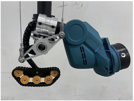
Fig. 18. Passive crawler mechanism to reduce ground pressure.
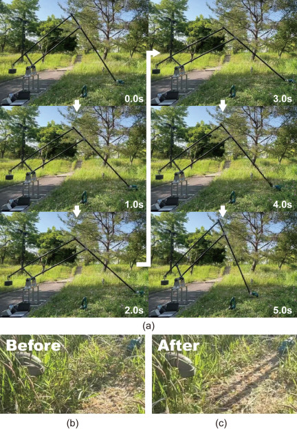
Fig. 19. Frame-by-frame images during the outdoor repetitive motion experiment on flat ground (a) and the vegetation before (b) and after (c) the mowing.
In this experiment, a sinusoidal reciprocating trajectory with an amplitude of 0.75 m was defined, centered on a point 2-m horizontally ahead of the base. At this stage, this value was empirically determined. Moving to a higher position prevents adequate grass cutting, while setting the target value lower forces the arm end to press too hard against the ground, making horizontal reciprocating motion impossible.
Figure 19 presents frame-by-frame images of the outdoor mowing experiment on approximately flat terrain and vegetation before and after the mowing.
Figure 20 shows the target and actual joint angles and measured joint torque of the first and second axes during the outdoor experiment with flat ground contact. Joint 1 achieved good tracking performance toward the target value, while joint 2 did not yield satisfactory results. This result implies that ground reaction forces in the horizontal (tangential) direction primarily hindered the arm’s motion. As a result, the maximum absolute joint torque value at joint 2 reached approximately 60 Nm. Although this value exceeded the continuous rated torque of the actuator (48 Nm), it remained below the allowable peak torque limit (120 Nm). The large torque was generated transiently by tangential ground reaction forces during terrain-contact motion, and stable operation was maintained throughout the experiment without mechanical instability.
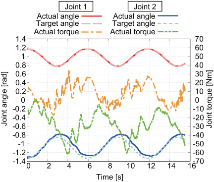
Fig. 20. Target and actual joint angles and measured joint torque of the first and second axes during the outdoor experiment with the flat ground contact.
4.2.2. Experiment 6: Repetitive Motion Test of the Arm End on Sloped Terrain
Next, an experiment was conducted to remove weeds from slopes where manual mowing has posed a significant risk. The geometrical relationship between the robot arm on the slope ground during the outdoor experiment is illustrated in Fig. 21. In a similar way to Section 4.2.1, a sinusoidal reciprocating trajectory with an amplitude of 1 m was defined. However, the trajectory of the reciprocating motion was set to move parallel to the slope. The slope angle is approximately 40°, which is highly dangerous for humans to perform weeding.
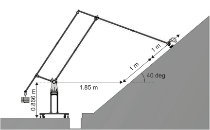
Fig. 21. Geometrical relationship between the robot arm and the slope ground during the outdoor experiment.
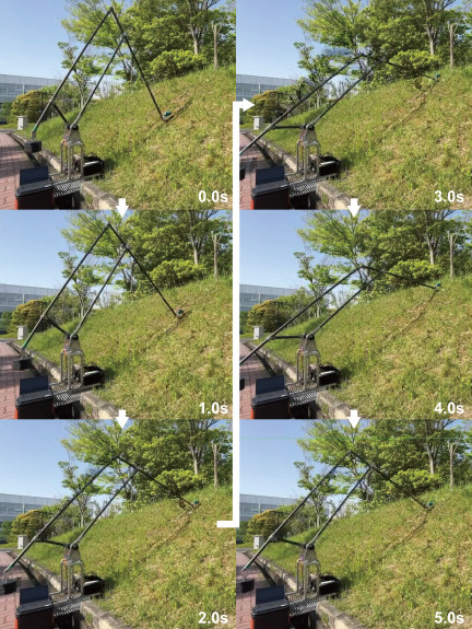
Fig. 22. Experiment frame-by-frame image during the outdoor repetitive motion test of the arm end on slope ground.
Figure 22 shows the frame-by-frame video of the outdoor experiment on sloped ground. It was again confirmed that the robot arm can adapt to the inclined terrain while performing grass-cutting. The experiment verified that the proposed robot arm could perform repetitive terrain-contact motion while maintaining contact between the brush-cutter head and the sloped ground surface. Although the amount of removed vegetation was limited in the experimental environment, the results demonstrated that the arm end could continuously trace the slope surface while operating the brush cutter. This suggests the feasibility of applying the proposed lightweight compliant structure to mowing-oriented terrain-contact tasks on hazardous slopes.
Figure 23 shows the target and actual joint angles and measured joint torque of the first and second axes during the outdoor experiment with slope ground contact. Although both joints 1 and 2 did not have good tracking performance toward the target value, the errors were not significantly large. In particular, when the arm end descended the slope, the convergence deteriorated due to disturbances from the ground. Moreover, during horizontal motion, links 1 and 2 rotate symmetrically left and right; thus, the directions of torques at joints 1 and 2 were also symmetrically positive and negative. However, on the slope, the arm end is constantly lifted diagonally upward, and both torques at joints 1 and 2 were often plotted in the same positive region.
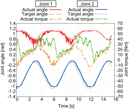
Fig. 23. Target and actual joint angles and measured joint torque of the first and second axes during the outdoor experiment with the slope ground contact.
5. Conclusions
This paper presented “ParaLambda,” a lightweight long-reach robot arm using highly backdrivable quasi-direct drive actuators for outdoor terrain-contact mowing tasks. To realize both long-reach and passive terrain compliance, the proposed system combines a lightweight CFRP parallel-link structure with low-gain position control using highly backdrivable actuators. The developed prototype achieved a maximum reach of 4.15 m, while maintaining an arm weight of 8.35 kg.
Indoor experiments verified the fundamental characteristics of the proposed system, including arm end backdrivability, repetitive long-reach motion, and terrain-contact operation without dedicated force/torque sensors. The results indicated that the lightweight compliant structure could maintain stable motion while utilizing environmental contact to reduce actuator load.
Furthermore, outdoor mowing experiments on flat and sloped terrain demonstrated that the robot arm could adapt to uneven outdoor environments while maintaining practical terrain-contact mowing operation. In particular, terrain-contact operation was achieved even on approximately 40° slopes, where conventional manual mowing operation may become quite hazardous.
The experimental results demonstrated that a lightweight long-reach manipulator with highly back-drivable actuators can utilize passive environmental contact to perform outdoor terrain-contact tasks without dedicated force/torque sensors. They also suggested that the structural flexibility of the CFRP links contributed significantly to passive terrain adaptation in addition to compliance generated by low-gain joint control.
The current prototype mainly focuses on planar motion. Future work includes extension toward three-dimensional motion by introducing an additional rotational axis at the base. Furthermore, suppression of out-of-plane vibration similar to previous compliant long-reach manipulator studies 6,7 and improvement of terrain-contact performance under more severe outdoor conditions remain important future research topics.
- [1] M. Takeichi, K. Suzumori, G. Endo, and H. Nabae, “Development of Giacometti Arm with Balloon Body,” IEEE Robotics and Automation Letters, Vol.2, No.2, pp. 951-957, 2017. https://doi.org/10.1109/LRA.2017.2655111
- [2] G. Endo, A. Horigome, and A. Takata, “Super Dragon: A 10-m-Long-Coupled Tendon-Driven Articulated Manipulator,” IEEE Robotics and Automation Letters, Vol.4, No.2, pp. 934-941, 2019. https://doi.org/10.1109/LRA.2019.2894855
- [3] A. Takata and G. Endo, “Dynamics-Based Control and Path Planning Method for Long-Reach Coupled Tendon-Driven Manipulator,” J. Robot. Mechatron., Vol.36, No.1, pp. 30-38, 2024. https://doi.org/10.20965/jrm.2024.p0030
- [4] Y. Yoshimitsu and S. Ikemoto, “Development of Tensegrity Manipulator Driven by 40 Pneumatic Cylinders for Investigating Functionality in Hyper-Redundant Musculoskeletal Systems,” J. Robot. Mechatron., Vol.35, No.5, pp. 1366-1373, 2023. https://doi.org/10.20965/jrm.2023.p1366
- [5] S. Hirose, T. Ishii, and A. Haishi, “Float Arm V: Hyper-redundant Manipulator with Wire-driven Weight-compensation Mechanism,” Proc. of 2003 IEEE Int. Conf. on Robotics and Automation, pp. 368-373, 2003. https://doi.org/10.1109/ROBOT.2003.1241623
- [6] M. Freese, S. P. N. Singh, W. Singhose, E. F. Fukushima, and S. Hirose, “Terrain Modeling and Following Using a Compliant Manipulator for Humanitarian Demining Applications,” A. Howard, K. Iagnemma, and A. Kelly (Eds.), “Field and Service Robotics,” pp. 3-12, Springer, 2010. https://doi.org/10.1007/978-3-642-13408-1_1
- [a] M. Freese, E. F. Fukushima, S. Hirose, and W. Singhose, “Endpoint Vibration Control of a Mobile Mine-Detecting Robotic Manipulator,” Proc. of the American Control Conf., pp. 1724-1729, 2007. https://doi.org/10.1109/ACC.2007.4282908
- [b] “Yaskawa GP120RL Website.” https://www.yaskawa.eu.com/robotics/robots/handling-mounting/productdetail/product/gp120rl_5936 [Accessed September 30, 2025]
- [c] “Kawasaki Robotics RS015X Website.” https://kawasakirobotics.com/asia-oceania/products-robots/rs015x/ [Accessed September 30, 2025]
- [d] “Hibot Float Arm Website.” https://hibot.co.jp/ja/float-arm/ [Accessed September 30, 2025]
- [e] “Huskvarna Website.” https://www.husqvarna.com/jp/robotic-lawn-mowers/ [Accessed September 30, 2025]
- [f] “Spider Website.” https://www.spidermower.com/ [Accessed September 30, 2025]
- [g] “MURAG Website.” https://www.mulag.de/en/roadside-equipment/products/unimog-equipment/front-mower/ [Accessed September 30, 2025]
- [h] “Husqvarna Zenoah Website.” https://www.zenoah.com/jp/weed-mowers/khm400w/ [Accessed September 30, 2025]
- [i] “Makita Website.” https://www.makita.co.jp/product/detail/?&model=MUR193D [Accessed September 30, 2025]
This article is published under a Creative Commons Attribution-NoDerivatives 4.0 Internationa License.