Paper:
Development of a Biomimetic Wire-Driven Fish Robot with Flexible Outer Skin for Carangiform Swimming
Daisuke Nakanishi
 , Shota Watanabe, Araki Ishitobi, and Kohei Ishihara
National Institute of Technology, Matsue College
14-4 Nishi-Ikumacho, Matsue, Shimane 690-8518, Japan

Screw propellers, while commonly used in underwater propulsion, suffer from issues such as entanglement, noise, and reduced visibility. In contrast, fish tail fin propulsion offers minimal environmental impact, superior obstacle avoidance, and high maneuverability in confined spaces, thus exhibiting excellent compatibility with underwater environments. Consequently, fish-like robots are considered promising for underwater exploration in disaster zones and ecological surveys. Although various fish-like robots have been developed, replicating the smooth, continuous streamlined shape of real fish using multi-link structures remains challenging. While flexible materials have been employed to create continuous structures, issues concerning body shape and surface integrity during swimming persist. Therefore, this study aims to develop a robot that maintains a continuous streamlined body shape using a silicone-based outer skin. The robot’s external shape is designed based on 3D scan data of Japanese horse mackerel, and a wire-driven bending mechanism with a flexible outer skin that prevents wrinkling during bending is developed. Swimming experiments demonstrated that the developed robot maintained a smooth and continuous body structure without wrinkles during bending, successfully replicating carangiform swimming, particularly the coordinated movement of the tail fin and body. Furthermore, the relationship between the robot’s swimming speed and tail fin frequency closely matched that of a real horse mackerel, confirming the achievement of efficient swimming.
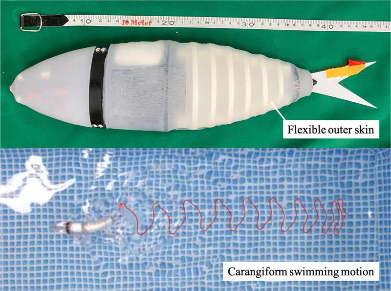
Wire-driven fish robot with flexible outer skin
1. Introduction
In underwater propulsion systems, screw propellers are widely employed in ships and underwater drones due to their high propulsion efficiency 1,2,3. However, screw propellers are susceptible to becoming inoperable when foreign objects entangle the rotating shaft, making them unsuitable for environments with abundant seaweed or floating debris. Additionally, they generate noise that can adversely affect surrounding aquatic organisms and stir up sediment, impairing visibility. Conversely, fish tail fin propulsion, which does not rely on a rotating shaft, is less vulnerable to environmental interference and more resilient to underwater obstacles. The gentle water flow produced during propulsion minimizes noise and reduces the environmental impact. Moreover, fish-like propulsion offers high maneuverability, enabling sharp turns, and closely mimics the natural swimming motion of real fish. This reduces disturbance to surrounding organisms and demonstrates excellent compatibility with underwater environments. Consequently, fish-like robots hold significant promise for underwater exploration in disaster-stricken areas and ecological surveys requiring minimal disruption to aquatic life 4,5.
Therefore, numerous fish-like robots have been developed in prior research. Some designs utilize thin-plate structures actuated by servo motors or soft actuators to achieve locomotion 6,7,8,9,10. While these robots can achieve locomotion, they often struggle to replicate the smooth, continuous body shape of real fish. The prevailing approach to replicating fish body shape and bending motion involves multi-link mechanisms driven by servo motors 11,12,13,14. However, due to the inherent gaps between joints in these multi-link structures, achieving a continuous, streamlined shape akin to that of real fish remains challenging. This discontinuity is believed to contribute to reduced swimming efficiency. Furthermore, a continuous body structure capable of interacting with water along its lateral surface is essential to achieve high maneuverability, such as sharp turns.
To address this issue, previous studies have explored the use of flexible materials, such as silicone, to create continuous body structures, either by integrally molding the body or covering it with a flexible outer skin. However, robots actuated by fluidic mechanisms often exhibit body deformations that deviate from real fish swimming patterns 15. Similarly, robots employing soft actuators often feature bellows-like body surfaces, lacking the streamlined shape characteristic of fish 16,17. Moreover, many designs face issues such as limited bending regions or the formation of wrinkles in the outer skin during bending 18,19,20,21,22. Consequently, research on robots capable of maintaining a continuous, smooth body surface during swimming, as observed in real fish, remains insufficient.
Therefore, this study aims to develop a swimming structure that maintains a continuous, streamlined body shape by utilizing a silicone outer skin, addressing the issue of gaps inherent in conventional multi-link structures. The robot’s external shape is designed based on 3D scan data of Japanese horse mackerel Trachurus japonicus. A wire-driven mechanism is developed to enable body bending for swimming. Furthermore, a flexible outer skin that bends in coordination with the actuation system, without forming wrinkles, is developed. Swimming experiments are conducted to evaluate the effect of the flexible outer skin on swimming speed.
2. Wire-Driven Fish Robot with Flexible Outer Skin
This section details the development of a fish-like robot incorporating a wire-driven mechanism and a silicone outer skin. Initially, the robot’s external shape was modeled based on 3D scan data of a Japanese horse mackerel Trachurus japonicus. Subsequently, the specifics of the developed robot are described, divided into the head, torso, and outer skin components.
2.1. Robot Shape Modeling
To achieve a biomimetic fish form, the robot’s external shape was designed using 3D scan data obtained from a fresh horse mackerel. The horse mackerel was chosen as the model organism due to its representative carangiform swimming locomotion 23 and its availability.
The procedure for scanning the fish and generating the 3D model is as follows:
-
The fresh horse mackerel was fixed to a platform (secured to a board, as shown in Fig. 1(a)).
-
A 3D scan was performed using the photogrammetry application “Trnio.”
-
The resulting 3D scan data (Fig. 1(b)) were imported into the 3D CAD software SolidWorks. Parallel planes were created at 5 mm intervals, extending from the fish’s snout to its tail fin.
-
The 3D data were sectioned using the created planes, and the body width and height at each section were measured.
-
The relationships between body width and section position, and between body height and section position, were approximated using a quadratic fit.
-
Assuming each cross-section to be elliptical, an approximation of the section was generated in SolidWorks.
The 3D model of the horse mackerel, generated through the aforementioned procedure, is shown in Fig. 1(c). The external shape of the fish-like robot, described in the following section, was designed based on this 3D model. Although the cross-sectional shape near the caudal fin of real horse mackerel is closer to a rhombus than an ellipse, in this study all cross-sections were approximated as ellipses. In addition, the 3D model was created using measurements from a single specimen, which may not fully represent the morphology of the species. The potential influence of these differences in external shape and the associated modeling errors on swimming performance will be addressed in future work.
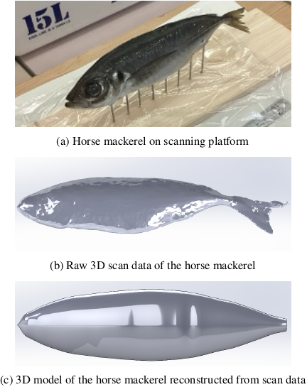
Fig. 1. 3D scanning process of a horse mackerel and resulting 3D model.
2.2. Robot Overview
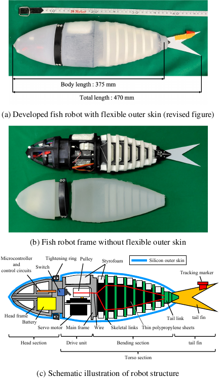
Fig. 2. Overview of the developed wire-driven fish robot with flexible outer skin.
The developed robot is presented in Fig. 2. The robot has a total length of 470 mm, a body length of 375 mm, and weighs 710 g (including a 25 g weight). In fish biology, the total length (\(\mathit{TL}\)) is defined as the distance from the tip of the upper jaw to the end of the caudal fin, while the body length (\(\mathit{BL}\)) is defined as the distance from the tip of the upper jaw to the base of the caudal fin. Following this convention, and as shown in Fig. 2, in the present robot, the total length is defined as the distance from the front end of the robot’s head to the tip of the caudal fin, and the body length is defined as the distance from the front end of the robot’s head to the screw fixing the caudal fin to the caudal fin link. The external shape of the robot was designed based on the previously described 3D model. However, to accommodate internal components, the original data were scaled up by a factor of two. The robot consists of a main frame, the head section, the torso section, and a flexible outer skin that encases them. The main frame was fabricated using stereolithography (SLA) 3D printing technology.
2.3. Head Section
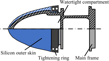
Fig. 3. Schematic illustration of the head section’s watertight structure using the flexible outer skin.
The structure of the head section is illustrated in Fig. 3. The head section, located at the anterior of the main frame, consists of a head frame and a flexible outer skin made of silicone. The head frame was fabricated using SLA 3D printing and is affixed to the main frame via screws. Inside the head frame, a 3.7 V lithium-ion battery (for the microcontroller), a 7.4 V lithium-polymer battery (for the servo motor), a microcontroller (M5Stack Technology, M5Stamp Pico), and its peripheral circuits are housed. Since the head section accommodates batteries and a microcontroller, it must be a watertight compartment. In prior studies 10,14, watertightness was achieved using an O-ring compressed by a lid at the opening. However, this method posed reliability and durability issues. Therefore, in this study, a new watertightness method utilizing the flexible outer skin was adopted. Specifically, the flexible outer skin is fitted over the head section, and its base is secured with a tightening ring to ensure watertightness (Fig. 3). The tightening ring was designed based on conventional sealing techniques, ensuring that the compressed part experiences a 10% reduction in both minor and major diameters for an effective seal. A preliminary experiment confirmed that this method provides sufficient watertightness performance. Additionally, the head frame is designed to open vertically, improving accessibility for battery replacement and maintenance.
2.4. Torso Section
The torso section comprises the drive unit, the bending section, and the tail fin.
2.4.1. Drive Unit
The drive unit consists of a servo motor (Flash Hobby, M45CHW) mounted on the main frame and a pulley attached to the servo motor. The pulley was fabricated using PLA filament via 3D printing. The wire-driven mechanism is illustrated in Fig. 4. Rotating the servo motor winds the wire, causing the torso section to bend. In contrast to previous studies 14, where the servo motor was positioned within the watertight anterior compartment, this study placed the servo motor near the midsection of the robot. This configuration enables only the posterior body to undulate, replicating the carangiform swimming characteristics of horse mackerel. Consequently, the servo motor is exposed to water, necessitating the use of a watertight servo motor. The servo motor is connected to the microcontroller via a servo motor driver (Pololu, Pololu G2 High-Power Motor Driver 24v13). Watertight cable glands (Ohm Electric, OA-WS04M-20/25) were employed to route power and signal wires from the watertight compartment to the control circuit. Additionally, a watertight toggle switch was installed in the same location for the robot’s power switch. Although the drive unit is exposed in Fig. 2(b), a cover was installed to maintain the fish-like form before encasing it with the flexible outer skin.
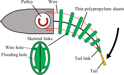
Fig. 4. Schematic illustration of the torso bending mechanism via wire actuation.
2.4.2. Bending Section
The bending section consists of a thin elastic plate (0.75 mm thick polypropylene sheet), skeletal links (PLA resin), tail link (TPU filament), and wires (0.40 mm polyester fishing line). The skeletal links and tail link were fabricated using 3D printing. The thin elastic plate is fixed to the main frame at its anterior end, while the tail link is attached to its posterior end. Six skeletal links, each 6 mm thick, were arranged along the thin elastic plate at 14 mm intervals. Each skeletal link was fastened to the elastic plate with two screws to prevent shifting due to outer skin movement. Each skeletal link contains four 2 mm holes to guide the wire, as shown in Fig. 4. To facilitate water passage through the torso section during swimming, multiple holes were incorporated into the skeletal links. The wire is threaded through the holes and secured to the tail link, with its length adjusted to maintain tautness in the torso’s neutral position.
2.4.3. Tail Fin
The tail fin was fabricated by cutting a 0.3 mm thick polystyrene sheet into the desired shape and attaching it to the tail link. The material and thickness were selected based on previous studies demonstrating high propulsion efficiency 24. The shape was designed with reference to 3D scan data of a horse mackerel. The tail link was fabricated from TPU filament, with its base designed in a triangular shape to enhance structural integrity and prevent breakage. Additionally, a tracking marker was affixed to the tail fin.
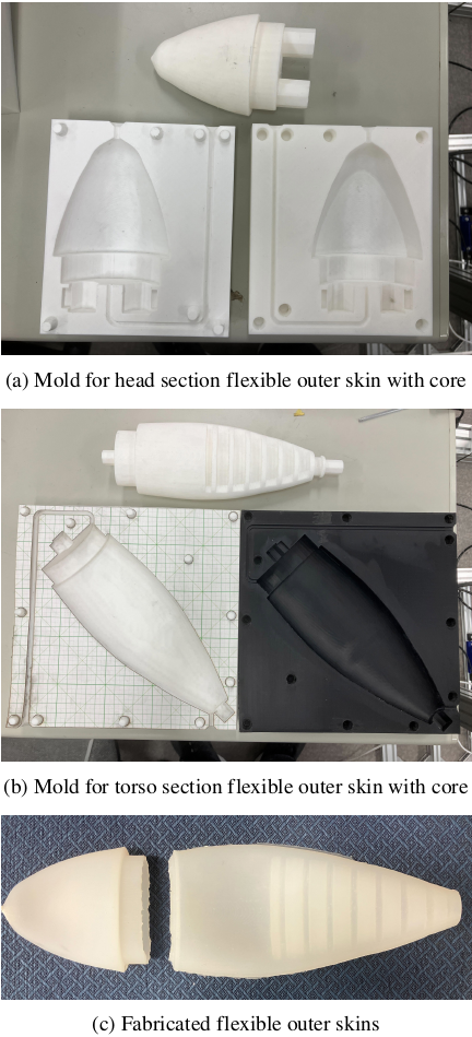
Fig. 5. Molds with cores and fabricated flexible outer skins.
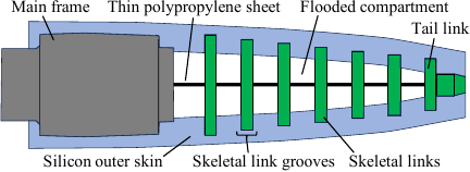
Fig. 6. Schematic illustration of the torso and flexible outer skin interlocking mechanism via skeletal link grooves.
2.5. Flexible Outer Skin
The flexible outer skin was fabricated separately for the head and torso sections. Following the methodology of previous research 25, the flexible outer skin was produced by casting silicone (Smooth-On, Ecoflex 30) into a mold generated using 3D printing. The mold and core employed in the fabrication process are illustrated in Figs. 5(a) and (b). The core is inserted into the mold to create a hollow section during casting.
2.5.1. Head Section
The fabricated flexible outer skin for the head section is shown in Fig. 5(c) (left). To ensure close contact between the flexible outer skin and the head section, the inner dimensions were directly derived from the 3D model of the horse mackerel’s head. The outer dimensions were determined by scaling the 3D model’s head: 1.15 times in the \(x\)-direction, 1.09 times in the \(y\)-direction, and 1.07 times in the \(z\)-direction, resulting in thicknesses of 2 mm in height and 3 mm in width. Consequently, the head section of the robot is slightly larger than that of the 3D model (Fig. 1(c)). As detailed in Section 2.3, the flexible outer skin is secured to the main frame via a tightening ring at a stepped section, ensuring watertightness for the entire head section.
2.5.2. Torso Section
The fabricated flexible outer skin for the torso section is shown in Fig. 5(c) (right). To enable the flexible outer skin to conform to the torso’s bending motion, grooves were incorporated into the inner surface to accommodate the skeletal links. An illustration of the flexible outer skin attached to the torso section is presented in Fig. 6. If the outer dimensions of the flexible outer skin were an exact match to the 3D model, wrinkles would form during torso bending. To mitigate this, the flexible outer skin was fabricated at 90% of the robot’s torso size. Consequently, when fitted onto the robot, the flexible outer skin is slightly stretched, reducing the likelihood of wrinkle formation during bending. The flexible outer skin is affixed to the torso section by fitting the skeletal links into the grooves. Additionally, the anterior end of the flexible outer skin features a stepped structure that engages with a groove on the head frame, securing it in place.
2.6. Preliminary Experiment
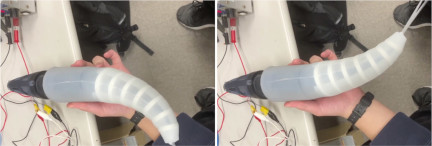
Fig. 7. Preliminary experiment: observing the absence of wrinkles in the flexible outer skin during torso bending in air.
A preliminary experiment was conducted to evaluate how well the flexible outer skin conformed to the torso’s bending motion and to assess any potential wrinkle formation. The experiment was performed in air, where the behavior of the outer skin was observed as the servo motor actuated the wire, inducing lateral bending in the torso. The results of the preliminary experiment are illustrated in Fig. 7. The observations confirmed that the flexible outer skin effectively conformed to the bending motion without significant wrinkle formation on its surface. The fish-like shape was maintained throughout the bending process. The absence of significant wrinkles indicates that the design of the flexible outer skin—specifically the 90% scaling of the torso size—successfully mitigated potential wrinkle formation during bending. This suggests that the outer skin will maintain a smooth profile during underwater operation, which is considered important for suppressing fluid resistance and enhancing propulsion efficiency.
3. Swimming Experiment
To investigate the effect of the flexible outer skin on swimming performance, swimming experiments were conducted with and without the skin.
3.1. Experimental Conditions
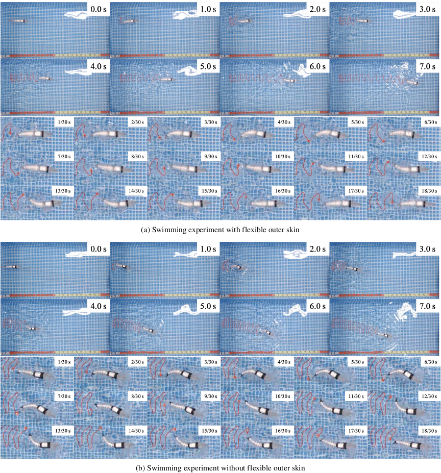
Fig. 8. Sequential images from swimming experiments at \(\theta = 60\)°, \(f = 1.75\) Hz.
The experiments employed a stepwise input to the servo motor, intermittently actuating the wire to induce lateral bending of the torso. Specifically, the servo motor’s angle command alternated between \(\tilde{\theta} + \theta\) [°] and \(\tilde{\theta} - \theta\) [°] every \(T/2\) [ms]. Here, \(T\) [ms] represents the period of one complete tail fin oscillation, \(\tilde{\theta}\) [°] is the servo’s reference angle, and \(\theta\) [°] is the pulley’s rotation angle, determining the wire winding amount. The wire length was meticulously adjusted to ensure tautness when the servo angle was at \(\tilde{\theta}\) for both bending directions. The swimming experiments utilized two key parameters: the tail fin frequency \(f\) [Hz] and the wire winding angle \(\theta\). The tail fin frequency, calculated as \(f = 1/T\), dictates the tail fin movement frequency. The wire winding angle \(\theta\) determines the tail fin amplitude, with larger angles resulting in greater amplitudes.
Experiments were conducted in a \(1.5~\mathrm{m} \times 2.5~\mathrm{m}\) indoor pool, with a ceiling-mounted camera recording the swimming process. The trajectory of the robot’s tail fin marker was tracked using Kinovea tracking software, and the tail fin’s movement was recorded. The tracking data were then approximated by a second-degree polynomial and integrated to calculate the swimming distance. The swimming speed was computed by dividing the swimming distance by the swimming time. The transient state, defined as the initial 500 mm of swimming, was excluded from speed calculations. Swimming speed was calculated using data from 500 mm to 1,500 mm from the starting point. The following parameter sets were utilized:
-
Pulley rotation angles \(\theta\): 30°, 45°, and 60° (3 patterns)
-
Tail fin frequencies \(f\): 0.50 Hz to 1.75 Hz, in 0.25 Hz increments (6 patterns)
-
Presence or absence of flexible outer skin (2 patterns)
This resulted in a total of 36 parameter sets. Each experiment was repeated three times per parameter set, and the mean, variance, and standard deviation of the swimming speed data were calculated.
Here, the outer skin on the head was always attached to ensure waterproofing of the control unit. Thus, “without outer skin” refers to the condition in which the flexible outer skin on the torso was removed, while “with outer skin” refers to the condition in which the flexible outer skin on the torso was attached. Regarding buoyancy, in the “without outer skin” condition, pieces of styrofoam were placed on the dorsal side of the main frame and on both the dorsal and ventral sides of the torso section (Fig. 2), so that the robot maintained a posture in which its head slightly emerged above the water surface while most of the body remained submerged during swimming. In the “with outer skin” condition, the robot became heavier due to the additional weight of the flexible outer skin. To compensate for this, a small amount of air was intentionally retained inside the flexible outer skin when it was filled with water. By adjusting the volume of this retained air, the experiments were conducted under buoyancy conditions equivalent to those in the “without outer skin” condition.
3.2. Experimental Results
Figure 8 shows the swimming experiment results for the robot with and without the flexible outer skin, using a winding angle of \(\theta = 60\)° and a tail fin frequency of \(f = 1.75\) Hz. The flexible outer skin effectively conformed to the links and exhibited no wrinkle formation during torso bending. Notably, the characteristic swimming motion of horse mackerel, involving both torso and tail fin bendings, was successfully replicated. However, observations revealed a reduced tail fin movement amplitude with the flexible outer skin attached, compared to the unmounted condition, under identical parameter settings.
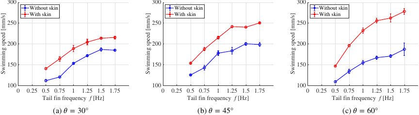
Fig. 9. Swimming speed vs. tail fin frequency (average speed \(\pm\) standard deviation) at different servo winding angles \(\theta\).
Figure 9 presents the measured swimming speeds derived from the experimental data. The plotted values represent the average swimming speed, with error bars indicating the standard deviation. The graph demonstrates a consistent trend of increased swimming speed with higher tail fin frequencies, regardless of the presence or absence of the flexible outer skin. Furthermore, the robot consistently achieved higher swimming speeds with the flexible outer skin attached across all experimental conditions. Additionally, the swimming speed increased with the winding angle \(\theta\) when the flexible outer skin was attached. Conversely, the unmounted condition showed no significant increase in swimming speed with larger winding angles \(\theta\). The maximum swimming speed achieved in this experiment was 278.2 mm/s, corresponding to a speed-to-body-length ratio of 0.591. This peak performance was observed with the flexible outer skin attached, a winding angle of \(\theta = 60\)°, and a tail fin frequency of \(f = 1.75\) Hz.
3.3. Discussion
Table 1. Relationship between servo winding angle and tail fin amplitude.

First, we discuss the effect of the flexible outer skin on the tail fin amplitude. Table 1 presents the tail fin amplitude measured with and without the flexible outer skin in air, under quasi-static conditions with a sufficiently large tail fin period \(T\). The results indicate a decrease in tail fin amplitude when the flexible outer skin is attached. This reduction is attributed to the flexible outer skin’s constraint on torso bending, which consequently limits the tail fin amplitude. However, despite this amplitude reduction, the actual swimming speed was higher with the flexible outer skin attached. This suggests that the hydrodynamic advantages of the flexible outer skin compensate for, or potentially surpass, the limitations imposed on torso bending.
Next, we examine the influence of each parameter on swimming speed. With the flexible outer skin attached, both tail fin frequency and amplitude exhibit a positive correlation with swimming speed. This observation aligns with the swimming behavior of real fish, where swimming speed increases with both tail fin frequency and amplitude 26. Conversely, without the flexible outer skin, although tail fin frequency still showed a positive correlation with swimming speed, the overall swimming speed was lower. Furthermore, no significant improvement in swimming speed was observed with increased tail fin amplitude in the absence of the outer skin. This discrepancy could be attributed to variations in body structure, which influence fluid resistance and, consequently, swimming speed. In carangiform swimming, reverse Kármán vortex streets generated by tail fin and torso undulations provide thrust through reaction force 27. Suboptimal body or tail fin structures can disrupt flow patterns, leading to increased resistance and diminished propulsion efficiency. These results suggest that the developed robot, with appropriate design considerations, effectively replicates fish-like swimming. Future investigations will involve conducting fluid simulations to comprehensively analyze the fluid dynamic effects of the flexible outer skin.
Furthermore, we assess the robot’s swimming capability using the swimming number \(S_w\), a metric for evaluating swimming performance in fish 28,26. \(S_w\) is defined as the ratio of swimming speed \(U\) to body length \(\mathit{BL}\), and can be calculated using the tail fin frequency \(f\) as
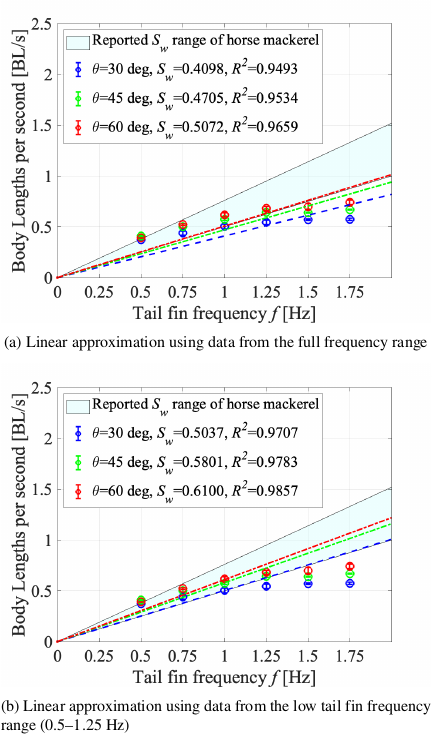
Fig. 10. Analysis of fishiness: Linear correlation between speed-to-body-length ratio and tail fin frequency in swimming experiments with flexible outer skin. The shaded area indicates the reported \(S_w\) range (0.50–0.76) for horse mackerel 28.
4. Conclusion and Future Work
This study developed a wire-driven, fish-like robot biomimetically designed to resemble the horse mackerel, with a focus on a flexible outer skin that prevents wrinkle formation during bending. Swimming experiments were conducted to evaluate the robot’s swimming speed and efficiency. The experimental results confirmed that the robot successfully maintained a continuous curved surface without wrinkle formation in the outer skin, replicating fish-like swimming behavior. Moreover, the robot achieved significantly higher swimming speeds and efficiencies with the flexible outer skin compared to the unmounted condition. A positive correlation between swimming speed and tail fin frequency was observed, consistent with the behavior of real fish. The evaluation using \(S_w\) also showed that the robot’s swimming efficiency was comparable to that of horse mackerel.
In the future, we will conduct experiments such as high-frame-rate video recording and fluid resistance measurements to examine in greater detail the differences between the robot and real fish swimming, as well as the effects of body shape and the use of the flexible outer skin on swimming performance and fluid resistance. Although the servo motor limited the robot’s tail fin frequency to 1.75 Hz, a decrease in swimming speed in the high-frequency range was also observed, possibly due to reduced amplitude. In contrast, real horse mackerel achieve cruising frequencies of approximately 5–6 Hz and peak frequencies up to 10 Hz during rapid swimming 29. Prior studies have demonstrated that brushless motors can achieve tail fin frequencies exceeding 10 Hz 7. Future work will focus on the implementation of alternative actuators to achieve higher tail fin frequencies and swimming speeds. Additionally, the continuous curved body structure developed in this study is expected to allow the robot to perform sharp turns through significant body bending at high swimming speeds.
- [1] H. Yamagata, S. Kochii, H. Yoshida, Y. Nogi, and T. Maki, “Development of AUV MONACA – Hover-Capable Platform for Detailed Observation Under Ice –,” J. Robot. Mechatron., Vol.33, No.6, pp. 1223-1233, 2021. https://doi.org/10.20965/jrm.2021.p1223
- [2] A. Okamoto, M. Imasato, S. C. Hirao, H. Sekiguchi, T. Seta, M. Sasano, and T. Fujiwara, “Development of Testbed AUV for Formation Control and its Fundamental Experiment in Actual Sea Model Basin,” J. Robot. Mechatron., Vol.33, No.1, pp. 151-157, 2021. https://doi.org/10.20965/jrm.2021.p0151
- [3] R. Miyakawa, S. Yamada, K. Sugimoto, K. Ishii, and Y. Nishida, “Sargassum Bed Survey Using AUV with a Disturbance Observer for Tidal Currents Estimation,” J. Robot. Mechatron., Vol.37, No.1, pp. 240-248, 2025. https://doi.org/10.20965/jrm.2025.p0240
- [4] F. E. Fish, “Advantages of Natural Propulsive Systems,” Marine Technology Society J., Vol.47, No.5, pp. 37-44, 2013. https://doi.org/10.4031/MTSJ.47.5.2
- [5] P. Bandyopadhyay, “Trends in Biorobotic Autonomous Undersea Vehicles,” IEEE J. of Oceanic Engineering, Vol.30, Issue 1, pp. 109-139, 2005. https://doi.org/10.1109/JOE.2005.843748
- [6] P. L. Nguyen, B. R. Lee, and K. K. Ahn, “Thrust and swimming speed analysis of fish robot with non-uniform flexible tail,” J. of Bionic Engineering, Vol.13, No.1, pp. 73-83, 2016. https://doi.org/10.1016/S1672-6529(14)60161-X
- [7] K. Iguchi, T. Shimooka, S. Uchikai, Y. Konno, H. Tanaka, Y. Ikemoto, and J. Shintake, “Agile robotic fish based on direct drive of continuum body,” npj Robotics, Vol.2, No.1, Article No.7, 2024. https://doi.org/10.1038/s44182-024-00014-z
- [8] W. Zhao, A. Ming, M. Shimojo, Y. Inoue, and H. Maekawa, “Fluid-Structure Interaction Analysis of a Soft Robotic Fish Using Piezoelectric Fiber Composite,” J. Robot. Mechatron., Vol.26, No.5, pp. 638-648, 2014. https://doi.org/10.20965/jrm.2014.p0638
- [9] Z. Wang, G. Hang, J. Li, Y. Wang, and K. Xiao, “A micro-robot fish with embedded SMA wire actuated flexible biomimetic fin,” Sensors and Actuators A: Physical, Vol.144, Issue 2, pp. 354-360, 2008. https://doi.org/10.1016/j.sna.2008.02.013
- [10] D. Nakanishi, S. Kobayashi, K. Obara, S. Matsumura, and Y. Sueoka, “Development of a Fish-Like Robot with a Continuous and High Frequency Snap-Through Buckling Mechanism Using a Triangular Cam,” J. Robot. Mechatron., Vol.33, No.2, pp. 400-409, 2021. https://doi.org/10.20965/jrm.2021.p0400
- [11] K. Hirata, T. Takimoto, and K. Tamura, “Study on Turning Performance of a Fish Robot,” 1st Int. Symp. on Aqua Bio-Mechanisms, pp. 287-292, 2000.
- [12] J. Yu, M. Tan, S. Wang, and E. Chen, “Development of a Biomimetic Robotic Fish and Its Control Algorithm,” IEEE Trans. on Systems, Man and Cybernetics, Part B (Cybernetics), Vol.34, Issue 4, pp. 1798-1810, 2004. https://doi.org/10.1109/TSMCB.2004.831151
- [13] Y. Takada, K. Koyama, and T. Usami, “Robotic Fish,” J. Robot. Mechatron., Vol.26, No.3, pp. 391-393, 2014. https://doi.org/10.20965/jrm.2014.p0391
- [14] D. Nakanishi and Y. Yoshioka, “Development of Continuous Snap-through Buckling Driven Fish Robot with Large Trapezoidal Elastic Sheet,” Trans. of the Society of Instrument and Control Engineers, Vol.60, Issue 1, pp. 70-72, 2024. https://doi.org/10.9746/sicetr.60.70
- [15] J. Z. Zhang, Y. Zhang, P. Ma, E. Nava, T. Du, P. Arm, W. Matusik, and R. K. Katzschmann, “Sim2Real for Soft Robotic Fish via Differentiable Simulation,” 2022 IEEE/RSJ Int. Conf. on Intelligent Robots and Systems (IROS), pp. 12598-12605, 2022. https://doi.org/10.1109/IROS47612.2022.9981338
- [16] S.-D. Gravert, M. Y. Michelis, S. Rogler, D. Tscholl, T. Buchner, and R. K. Katzschmann, “Planar Modeling and Sim-to-Real of a Tethered Multimaterial Soft Swimmer Driven by Peano-HASELs,” 2022 IEEE/RSJ Int. Conf. on Intelligent Robots and Systems (IROS), pp. 9417-9423, 2022. https://doi.org/10.1109/IROS47612.2022.9981192
- [17] C. Rossi, J. Colorado, W. Coral, and A. Barrientos, “Bending continuous structures with SMAs: A novel robotic fish design,” Bioinspiration & Biomimetics, Vol.6, No.4, Article No.045005, 2011. https://doi.org/10.1088/1748-3182/6/4/045005
- [18] S. C. van den Berg, R. B. Scharff, Z. Rusák, and J. Wu, “OpenFish: Biomimetic design of a soft robotic fish for high speed locomotion,” HardwareX, Vol.12, Article No.e00320, 2022. https://doi.org/10.1016/j.ohx.2022.e00320
- [19] R. K. Katzschmann, J. DelPreto, R. MacCurdy, and D. Rus, “Exploration of underwater life with an acoustically controlled soft robotic fish,” Science Robotics, Vol.3, Issue 16, Article No.eaar3449, 2018. https://doi.org/10.1126/scirobotics.aar3449
- [20] I. Yamamoto and T. Hiratsuka, “Research and Development of Robotic Fish Based on Elastic Oscillation Fin System,” Proc. of the 2012 World Congress on Advances in Civil, Environmental, and Materials Research (ACEM’12), pp. 1820-1834, 2012.
- [21] Z. Chen, X. Tian, X. Chen, B. Wen, and X. Li, “An experimental study of the wire-driven compliant robotic fish,” Ocean Engineering, Vol.279, Article No.114433, 2023. https://doi.org/10.1016/j.oceaneng.2023.114433
- [22] M. Shibata, “Fish-Like Robot with a Deformable Body Fabricated Using a Silicone Mold,” J. Robot. Mechatron., Vol.34, No.1, pp. 40-46, 2022. https://doi.org/10.20965/jrm.2022.p0040
- [23] C. M. Breder Jr., “The locomotion of fishes,” Zoologica: Scientific Contributions of the New York Zoological Society, Vol.4, Issue 5, pp. 159-297, 1926. https://doi.org/10.5962/p.203769
- [24] Y. Takada, Y. Nakanishi, R. Araki, and T. Wakisaka, “Investigation of Propulsive Force and Water Flow around a Small Fish Robot by PIV Measurement and Three-Dimensional Numerical Analysis (Mechanical Systems),” Trans. of the Japan Society of Mechanical Engineers, Series C, Vol.76, Issue 763, pp. 665-672, 2010 (in Japanese). https://doi.org/10.1299/kikaic.76.665
- [25] D. Nakanishi and K. Ishihara, “Development of snap-through buckling-driven fish-type robot with elastic outer skin,” Proc. of JSME Annual Conf. on Robotics and Mechatronics (Robomec), Session ID 2P2-B10, 2024 (in Japanese). https://doi.org/10.1299/jsmermd.2024.2P2-B10
- [26] R. Bainbridge, “The Speed of Swimming of Fish as Related to Size and to the Frequency and Amplitude of the Tail Beat,” J. of Experimental Biology, Vol.35, Issue 1, pp. 109-133, 1958. https://doi.org/10.1242/jeb.35.1.109
- [27] I. Honda, O. Kawanami, and Y. Kawashima, “Numerical Visualization of Flow Around Oscillating Caudal Fin,” J. of the Visualization Society of Japan, Vol.30, Issue 119, pp. 22-27, 2010 (in Japanese). https://doi.org/10.3154/jvs.30.22
- [28] M. Yokota, K. Yamamoto, Y. Taira, T. Handa, and E. Morimoto, “Oxygen consumption and swimming ability of Trachurus japonicus,” J. of National Fisheries University, Vol.56, Issue 4, pp. 267-271, 2008.
- [29] G. Xu, T. Arimoto, and M. Inoue, “The measurements of swimming speed in jack mackerel Trachurus japonicus,” Nippon Suisan Gakkaishi, Vol.54, Issue 9, pp. 1493-1497, 1988 (in Japanese). https://doi.org/10.2331/suisan.54.1493
This article is published under a Creative Commons Attribution-NoDerivatives 4.0 Internationa License.