Paper:
Mobile Robot Utilizing the Rotational Motion of its Arms —Effect of Applying an Oscillation Mechanism—
Ryota Hayashi*1, Ryo Oishi*2, Yasuyuki Setoyama*3, Koji Yoshida*1, and Tetsuya Kinugasa*4

*1Department of Mechanical Systems Engineering, Okayama University of Science
1-1 Ridai-cho, Kita-ku, Okayama, Okayama 700-0005, Japan
*2Graduate School of Science and Engineering, Okayama University of Science
1-1 Ridai-cho, Kita-ku, Okayama, Okayama 700-0005, Japan
*3Department of Electronic Control Engineering, National Institute of Technology, Kagoshima College
1460-1 Shinko, Hayato-cho, Kirishima, Kagoshima 899-5193, Japan
*4Department of Robotics, Kindai University
1 Takaya Umenobe, Higashi-Hiroshima, Hiroshima 739-2116, Japan

In this study, we propose a mobile robot that can start moving by utilizing the rotational movements of its two arms. The robot has two rotating arms and a body. It is equipped with a device that can fix its body to a platform constructed on a wall or floor. When the body is fixed to the platform, the robot can store the kinetic momentum of its center of mass by rotating its arms. When the body is released from the platform, the robot begins to move along the kinetic momentum of its center of mass. In our previous study, we demonstrated the feasibility of a mobile robot that hopped up and down the steps under Earth’s gravity, and we assessed its performance of the robot by performing numerical simulations. In the present study, we evaluated the performance of the mobile robot as it moved on a flat, low-friction floor, and we assessed the implementability of a device capable of fixing the robot’s body to a platform, by conducting a round-trip movement experiment. Furthermore, we proposed a modified mobile robot equipped with an oscillation mechanism and verified the feasibility of the modified mobile robot through comparative experiments.
Oscillating arm-rotation mobile robot
1. Introduction
Several rovers have been proposed for exploration under a micro-gravity environment on the surface of small planets 1,2,3. Therefore, it is imperative to develop mechanisms for mobile robots to enable these robots to operate in certain environments. Various types of mobile robots with different mechanisms have been developed over the years 4,5,6,7. Other types of robots have also been developed, which include a jumping robot 8 that controls its trajectory by adjusting its crawling and jumping take-off speeds, a spherical robot 9 that relies on the eccentric torque generated by the movement of an internal eccentric mass, and a portable cable-suspended parallel robot 10 designed for indoor inspections.
In this study, we proposed a novel mobile robot that can start moving by utilizing the rotational movements of its two arms. The robot consisted of two rotating arms and a body. The robot was also equipped with a device that can fix the robot’s body to a platform constructed on a wall or floor. When the body was fixed to the platform, the robot could store the kinetic momentum of its center of mass by rotating its arms. When the body was released from the platform, the robot began to move along the kinetic momentum of its center of mass. Unlike wheeled, crawler, and rolling robots, the proposed mobile robot does not require interactions with the environment. Therefore, it is well suited for movement in zero-gravity environments or in those in the absence of ground friction. The proposed mobile robot is also superior to conventional spring-powered jumping robots because it does not require a device to compress the springs. The mobile robot offers a novel mechanism for storing kinetic energy by rotating its arms, where the stored kinetic energy will be used for movement.
In our previous study, we verified the feasibility of the proposed mobile robot under Earth’s gravity. We demonstrated that an experimental model of a hopping robot could jump up and land on a step without tumbling by utilizing the rotational movements of its arms 11,12. We also assessed the performance of the proposed mobile robot that hopped to subsequent platforms under gravity environment through numerical simulations 13. In addition, we proposed a scheme for controlling the moving direction of the mobile robot, and we developed a method to reduce collision impacts with the subsequent platform in a frictionless planar space. Following this, we verified the proposed scheme and method through numerical simulations 14.
In this study, we evaluated the performance of the proposed mobile robot moving on a flat, low-friction floor, and we assessed the implementability of a device capable of fixing the robot’s body to the platform by conducting a round-trip movement experiment. Furthermore, we proposed a modified model of a robot equipped with an oscillation mechanism 15. Subsequently, we verified the feasibility of the modified mobile robot through comparative numerical simulations and experiments.
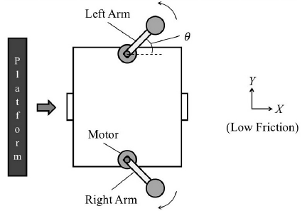
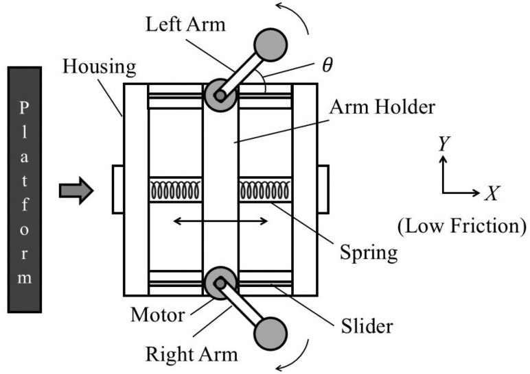
Fig. 1. Configuration of the proposed mobile robot.
2. Mobile Robot Utilizing the Rotational Motion of its Arms
2.1. Configuration of the Mobile Robot
The mobile robot consisted of two rotating arms and a body. Each joint of the arm was equipped with a motor. The mobile robot was equipped with a device that can fix its body to a platform constructed on a wall or floor (e.g., an electromagnet). When the body was fixed to a platform, the mobile robot could store the kinetic momentum of its center of mass by rotating its arms. We refer to this period as the “fixed state.” When the body was released from the platform, the mobile robot began to move along the kinetic momentum of its center of mass on a flat floor with low friction, as illustrated in Fig. 1. We refer to the period after the fixed state as the “released state.”
In this study, we considered that the left and right arms are rotated symmetrically with respect to the \(X\)-axis in the fixed state. Therefore, the mobile robot moves along the \(X\)-axis.
2.2. Mathematical Model of the Mobile Robot
Each arm of the mobile robot was equipped with a servo motor along its rotational axis. The motor torques of the left and right arms are denoted as \(\tau_{l}\) and \(\tau_{r}\), respectively. We assumed that the center of mass of each rotating arm is at its tip. The length and mass of each arm are denoted as \(r\) and \(m_{a}\), respectively. The rotation angles of the left and right arms with respect to the \(X\)-axis are denoted as \(\theta_{l}\) and \(\theta_{r}\), respectively. The viscous coefficient of the rotary joint of each arm is represented as \(c_{a}\). The viscous coefficient between the body of the mobile robot and the floor is represented as \(c_{b}\). The body of the mobile robot was square-shaped. We assumed that the center of mass of the body, including the motors, is at the center of the square. The mass and moment of inertia of the body are denoted as \(M\) and \(J_{b}\), respectively. The phase angle of the body with respect to the \(X\)-axis is denoted as \(\theta_{b}\). \((X_{b},Y_{b})\) represents the position of the body’s center of mass, whereas \((X_{g},Y_{g})\) represents the entire mobile robot’s center of mass position.
To develop a mathematical model of the mobile robot in the released state, the following equation of motion was introduced by incorporating the physical parameters mentioned above:
In this study, we considered that the left and right arms are rotated symmetrically with respect to the \(X\)-axis in the fixed state. The magnitude of torque of the left and right motors is the same as \(\tau_{l} = -\tau_{r} = \tau\). The relationship of the rotation angles of the left and right arms is denoted as \(\theta_{l} = -\theta_{r} = \theta\). We also assumed that \(\theta_{b} = 0\) and \(Y_{b} = 0\). Therefore, the mathematical model of the mobile robot can be rewritten as follows:
Table 1. Physical parameters of the mobile robot used in the numerical simulations.

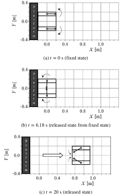
Fig. 2. Numerical simulations carried out to evaluate the performance of the mobile robot.
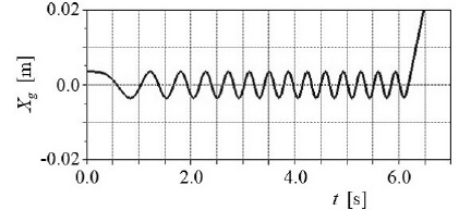
Fig. 3. Center-of-mass position \(X_{g}\).
2.3. Numerical Simulations
Numerical simulations were conducted to evaluate the performance of the proposed mobile robot. The numerical values of the physical parameters are presented in Table 1, and the results of the numerical simulations are shown in Fig. 2. We set the initial conditions at time \(t = 0\) s as \(\theta = 0\) rad and \(X_{b} = 0\) m (Fig. 2(a)). The torque of the motor was set as \(\tau = 0.01\) Nm. The left and right arms began to rotate symmetrically with respect to the \(X\)-axis. The center of mass oscillated along the \(X\)-axis in the fixed state.
When the kinetic momentum of the robot’s center of mass was directed along the \(X\)-axis with a sufficient magnitude of velocity, the body of the mobile robot was released from the platform and the torque of the motor was set as \(\tau = 0\) Nm (Fig. 2(b)). The mobile robot then moved along the kinetic momentum of its center of mass (Fig. 2(c)). If the viscous coefficient \(c_{b}\) between the body and floor was not zero, the mobile robot would have stopped after moving along the \(X\)-axis for certain period.
The time series of the center-of-mass displacement \(X_{g}\) is shown in Fig. 3. It can be seen that the center of mass oscillated along the \(X\)-axis in the fixed state and then the center of mass moved at a constant velocity along the \(X\)-axis in the released state.
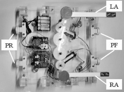
Fig. 4. Experimental model of the proposed mobile robot (LA: left arm, RA: right arm, PF: permanent magnets at the front, and PR: permanent magnets at the rear).
2.4. Experiment of the Proposed Mobile Robot
2.4.1. Experimental Model of the Mobile Robot
We constructed an experimental model of the mobile robot utilizing the rotational motion of its arms, as shown in Fig. 4.
Each joint of the arm was equipped with a motor (Maxon RE25-118743). The length and width of the body were 0.33 m and 0.33 m, respectively. The mass of the body, including the two motors, was 3.0 kg. The length of each arm was 0.18 m, and the mass of each arm was 0.03 kg. The left and right arms were designed such that the distance between their rotation axes was 0.21 m. Their planes of rotation were located at 0.15 m (left arm) and 0.13 m (right arm) from the floor. This design ensured that the arm tips did not contact anything. Four ball-shaped casters were attached to the underside of the body. The friction between the floor and body was considered to be small.
We constructed two platforms on a flat floor to allow the experimental model to perform a round trip between them. Each platform was equipped with a pair of electromagnets. The platform, which included a pair of electromagnets, was designed to have a maximum height of 0.11 m above the floor, ensuring that the arm tips never came into contact with it. The experimental model had a pair of permanent magnets at the front of the body and a pair of permanent magnets at the rear. Hence, the body of the experimental model could be fixed and released from each platform. The platform equipped with a pair of electromagnets is shown in Fig. 5.
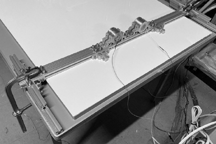
Fig. 5. Platform equipped with a pair of electromagnets on a flat floor.
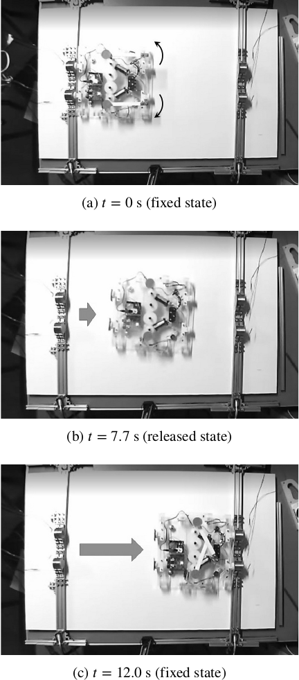
Fig. 6. Experimental model on an outbound trip.
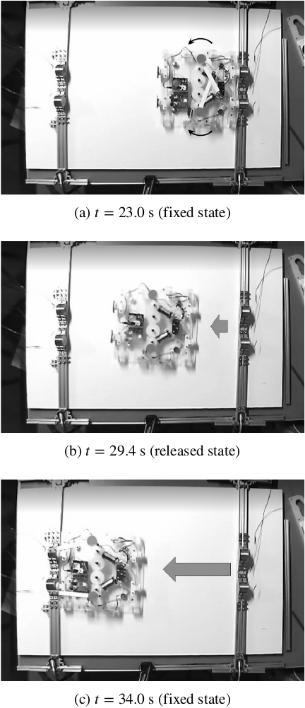
Fig. 7. Experimental model on a return trip.
2.4.2. Round-Trip Movement Experiment
We conducted a round-trip movement experiment using the experimental model to demonstrate the feasibility of the proposed mobile robot. The distance between the two platforms was set at 0.7 m. The experimental results captured by the charge-coupled device camera from above are shown in Figs. 6 and 7.
During the fixed state on the outbound trip, the body was fixed to the platform using a pair of electromagnets, and a maximum command voltage of 10 V was applied to each motor amplifier (Fig. 6(a)). The body was released when the kinetic momentum of the mobile robot in the positive \(X\)-axis direction was maximized (\(t = 6.9\) s). This timing was selected based on several experimental results to ensure that the mobile robot started at its maximum speed in these experiments. Here, the voltage applied to each motor amplifier was set at 0 V. The experimental model was then moved to the next platform (Fig. 6(b)). After the experimental model reached the next platform, the body was fixed to it using a pair of electromagnets (Fig. 6(c)). During the fixed state of the return trip, a maximum command voltage of 10 V was applied to each motor amplifier (Fig. 7(a)). The body was released when the kinetic momentum of the mobile robot in the negative direction of the \(X\)-axis was maximized (\(t = 23.6\) s). This timing was selected based on several experimental results to ensure that the mobile robot started at its maximum speed in these experiments. Here, the voltage applied to each motor amplifier was set at 0 V. The experimental model was then moved to the former platform (Fig. 7(b)). After the experimental model reached the former platform, the body was fixed to it using a pair of electromagnets (Fig. 7(c)).
Consequently, the feasibility of the proposed mobile robot was verified by conducting a round-trip movement experiment using the experimental model.
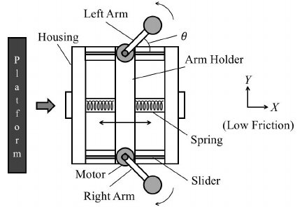
Fig. 8. Configuration of the modified mobile robot with an oscillation mechanism.
3. Modified Mobile Robot Equipped with an Oscillation Mechanism
3.1. Configuration of the Modified Mobile Robot with an Oscillation Mechanism
The experimental model mentioned in the previous section could only move a maximum distance of 0.35 m because there was uncertain friction between the body and floor. In this section, we discuss a modified mobile robot equipped with an oscillation mechanism, as illustrated in Fig. 8. By employing an oscillation mechanism, we believe that the modified mobile robot can store greater kinetic momentum in its center of mass compared with the previous model.
The body of the modified mobile robot consisted of a housing and an arm holder. The arm holder was fitted with two motors to rotate the arms. The two springs were arranged such that they sandwich the arm holder inside the body. One end of each spring was connected to the housing, whereas the other end was connected to the arm holder. The arm holder was designed to allow relative movement with respect to the housing only in the axial direction.
3.2. Mathematical Model of the Modified Mobile Robot
The notations of the physical parameters for the modified mobile robot model were almost identical to those of the previous model. \(M\) and \(J_{b}\) represent the mass and moment of inertia of the housing, respectively. The phase angle of the housing with respect to the \(X\)-axis is denoted as \(\theta_{b}\). The position of the center of mass of the housing is denoted as \((X_{b},Y_{b})\). \(m\) and \(J\) represent the mass and inertial moment of the arm holder, respectively, including those of the two motors. The displacement of the center of the arm holder in relation to the housing is represented as \(x\). The viscous coefficient between the arm holder and housing is represented as \(c_{h}\). The spring constant of the oscillation mechanism comprised of the arm holder and springs is denoted as \(k\).
To develop a mathematical model of the mobile robot in the released state, the following equation of motion was introduced by incorporating the physical parameters mentioned above:
In this study, we considered that the left and right arms are rotated symmetrically with respect to the \(X\)-axis in the fixed state. The magnitude of torque of the left and right motors is the same as \(\tau_{l} = -\tau_{r} = \tau\). The relation of the rotation angles of the left and right arms can be represented as \(\theta_{l} = -\theta_{r} = \theta\). We also assumed that \(\theta_{b} = 0\) and \(Y_{b} = 0\). Therefore, the mathematical model of the modified robot can be rewritten as follows:
Table 2. Physical parameters used for the comparative numerical simulations.

3.3. Comparative Numerical Simulations
Comparative numerical simulations were carried out to verify the effectiveness of the modified mobile robot with an oscillation mechanism. The physical parameters of the modified model are tabulated in Table 2. In the comparative numerical simulations, the physical parameters of the previous model were nearly identical to those of the modified model. However, the body mass of the previous model was \(M+m\) of the modified model.
The magnitude of velocity at the center of mass of the modified model was compared with that of the previous model in the fixed state, as shown in Fig. 9. The maximum velocities of the previous and modified models were 0.12 m/s and 0.30 m/s, respectively. These results show that the modified model can store greater kinetic momentum in its center of mass compared with the previous model.
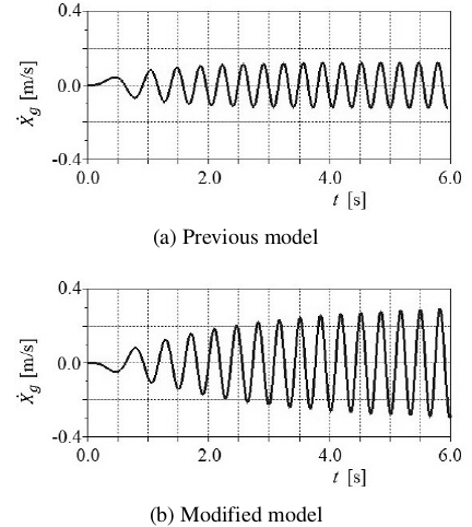
Fig. 9. Comparison of the center of mass velocities in the fixed state.
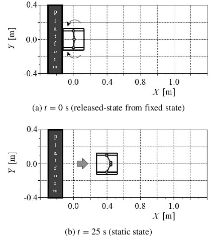
Fig. 10. Numerical simulation of the previous model with viscous friction between the body and floor.
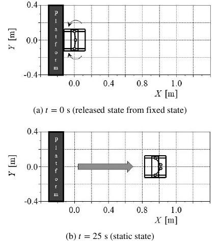
Fig. 11. Numerical simulation of the modified model with viscous friction between the body and floor.
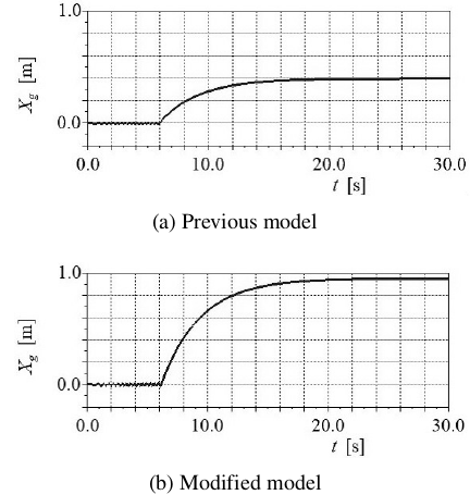
Fig. 12. Comparison of the center-of-mass displacements.
We conducted numerical simulations of the movements of both the previous and modified models with viscous friction between the body and floor, as shown in Figs. 10 and 11. The torque of the motor was set as \(\tau = 0.01\) Nm. The left and right arms began to rotate symmetrically with respect to the \(X\)-axis. The center of mass oscillated along the \(X\)-axis in the fixed state (Figs. 10(a) and 11(a)). Each body was released when the kinetic momentum of each model in the positive \(X\)-axis direction was maximized. Here, the torque of the motor was set as \(\tau = 0\) Nm. Because the viscous coefficient \(c_{b}\) between the body and floor was not zero, each model stopped after moving along the \(X\)-axis for a certain period (Figs. 10(b) and 11(b)). The previous model could only move a maximum distance of 0.40 m. In contrast, the modified model could move a maximum distance of 0.96 m.
The time series of the center-of-mass displacements are shown in Fig. 12. Based on these results, we could verify the effectiveness of the modified model with an oscillation mechanism.
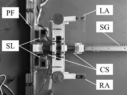
Fig. 13. Experimental model of the modified mobile robot (LA: left arm, RA: right arm, PF: platform, SL: solenoid latches, CS: coil spring, and SG: slide guide).
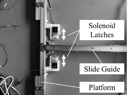
Fig. 14. Platform equipped with a pair of solenoid latches.
3.4. Comparative Experiments
3.4.1. Experimental Model of the Mobile Robot
We constructed an experimental model of the modified mobile robot with an oscillation mechanism utilizing the rotational motion of its arms, as shown in Fig. 13. The experimental model was designed to move only along the \(X\)-axis direction on the slide guide.
Each joint of the arm on the arm holder was equipped with a motor (Maxon RE25-118743). The length and width of the housing were 0.25 m and 0.25 m, respectively. The mass of the housing was 0.5 kg. The length and width of the arm holder were 0.25 m and 0.1 m, respectively. The mass of the arm holder, including the two motors, was 1.0 kg. The spring constant of the oscillation mechanism was 727 N/m. The length of each arm was 0.1 m and the mass of each arm was 0.05 kg. The distance between the axes of rotation for the left and right arms was designed to be 0.21 m, where the planes of rotation for the left and right arms were 0.13 m from the floor. This design ensured that the arm tips did not contact anything.
We constructed a platform on a flat floor to allow the experimental model to move away from it. The platform was equipped with a pair of solenoid latches, as shown in Fig. 14. The platform, which included a pair of solenoid latches, was designed to have a maximum height of 0.04 m above the floor, ensuring that the arm tips never touched it. The solenoid latches could secure the part attached to the housing in the fixed state. Hence, the housing could be fixed to and released from the platform by controlling the electric current of the solenoid latches. In this manner, the housing of the experimental model could be fixed to and released from the platform.
The experimental model included a fixture that enabled the arm holder to be fixed to the housing for the comparative experiments. When the arm holder was fixed to the housing using the fixture, the experimental model became the previous mobile robot without an oscillation mechanism.
3.4.2. Verification of the Feasibility of the Modified Mobile Robot Through Comparative Experiments
We conducted comparative experiments to demonstrate the effectiveness of the modified robot with an oscillation mechanism.
The experimental results of the previous mobile robot without an oscillation mechanism are shown in Fig. 15. In the fixed state, the housing was fixed to the platform using a pair of solenoid latches, and one-tenth of the maximum command voltage (1.0 V) was applied to each motor amplifier. The housing was released from the platform when the kinetic momentum of the previous mobile robot in the positive \(X\)-axis direction was maximized (Fig. 15(a)). Here, the voltage applied to each motor amplifier was set at 0 V. Because there was uncertain friction in the slide guide between the housing and floor, the previous mobile robot stopped after moving along the \(X\)-axis for a certain period (Figs. 15(b) and (c)). As a result, the previous mobile robot without the oscillation mechanism was able to move only 0.26 m from the platform. The initial velocity of the previous mobile robot was 0.26 m/s.
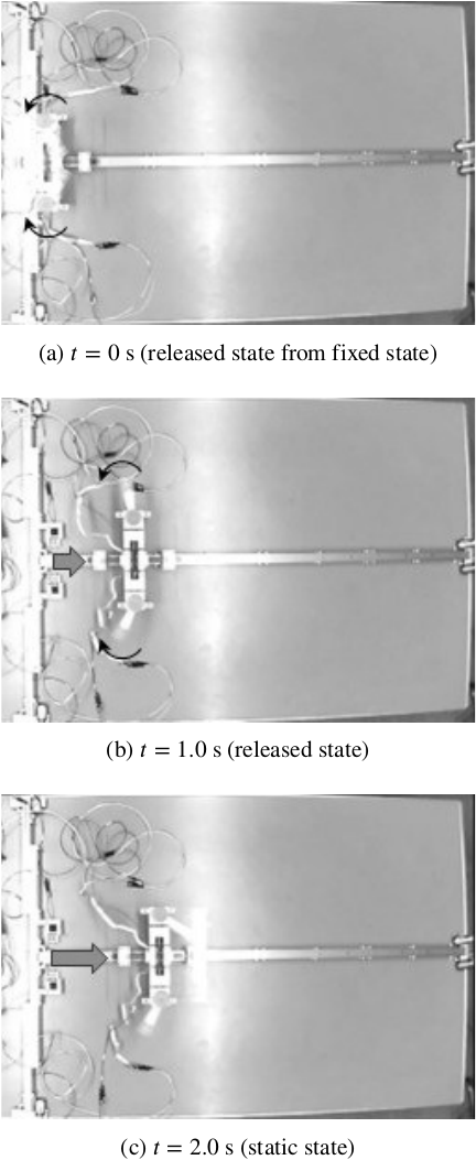
Fig. 15. Comparative experiment of the previous mobile robot without an oscillation mechanism.
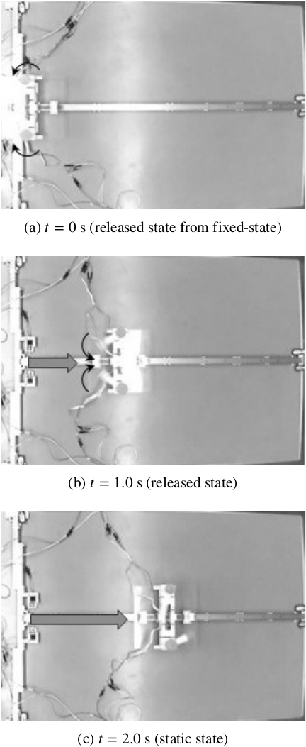
Fig. 16. Comparative experiment of the modified mobile robot with an oscillation mechanism.
The experimental results of the modified mobile robot with an oscillation mechanism are shown in Fig. 16. In the fixed state, the housing was fixed to the platform using a pair of solenoid latches, and the same one-tenth of the maximum command voltage (1.0 V) was applied to each motor amplifier. The housing was released from the platform when the kinetic momentum of the modified mobile robot in the positive \(X\)-axis direction was maximized (Fig. 16(a)). Here, the voltage applied to each motor amplifier was set at 0 V. Because there was uncertain friction in the slide guide between the housing and floor, the modified mobile robot stopped after moving along the \(X\)-axis for a certain period (Figs. 16(b) and (c)). Consequently, the modified mobile robot with an oscillation mechanism was able to move 0.55 m from the platform. The initial velocity of the modified mobile robot was observed to be 0.36 m/s. The initial velocity of the modified mobile robot with an oscillation mechanism was higher than that of the previous mobile robot without an oscillation mechanism.
These experimental results demonstrate the effectiveness of the modified mobile robot with an oscillation mechanism.
4. Conclusion
In this study, we proposed a novel mobile robot that can start moving by utilizing the rotational movements of its two arms. We verified the performance and feasibility of the proposed mobile robot, which moved on a flat floor with low friction, by conducting numerical simulations and a round-trip movement experiment. Furthermore, we proposed a modified model of the mobile robot equipped with an oscillation mechanism. Subsequently, we verified the effectiveness of the proposed modified mobile robot by conducting comparative numerical simulations and experiments.
The proposed modified mobile robot with an oscillation mechanism can store the kinetic momentum of its center of mass not only by rotating its arms, but also by utilizing the mechanical energy of the spring–mass oscillation system comprised of an arm holder and springs. The oscillation mechanism is not a simple one-degree-of-freedom spring–mass oscillation system because it consists of an arm holder, springs, and rotating arms that oscillate together. In the near future, we intend to investigate the relationship between the amplitude of the oscillation mechanism and the eigenfrequency of the spring–mass system.
- [1] T. Yoshimitsu, T. Kubota, and I. Nakatani, “MINERVA rover which became a small artificial solar satellite,” Proc. of the 20th Annual AIAA/USU Conf. on Small Satellites, Article No.SSC06-IV-4, 2006.
- [2] K. Nagaoka and K. Yoshida, “Modeling and analysis of ciliary micro-hopping locomotion actuated by an eccentric motor in a microgravity,” 2013 IEEE/RSJ Int. Conf. on Intelligent Robots and Systems, pp. 763-768, 2013. https://doi.org/10.1109/IROS.2013.6696437
- [3] M. Kurisu, “Design of a hopping mechanism using permanent magnets for small-scale exploration rovers,” 2014 IEEE/RSJ Int. Conf. on Intelligent Robots and Systems, pp. 2355-2360, 2014. https://doi.org/10.1109/IROS.2014.6942881
- [4] G. Kato, H. Kojima, M. Yoshida, and Y. Wakabayashi, “Experiments on motion control of two-joint articulated hopping robot with stopper mechanisms,” J. Robot. Mechatron., Vol.17, No.1, pp. 89-100, 2005. https://doi.org/10.20965/jrm.2005.p0089
- [5] Y. Asai et al., “Wheel-based stair climbing robot with hopping mechanism – Demonstration of Continuous Stair Climbing Using Vibration –,” J. Robot. Mechatron., Vol.20, No.2, pp. 221-227, 2008. https://doi.org/10.20965/jrm.2008.p0221
- [6] M. Ishikawa, R. Kitayoshi, and T. Sugie, “Volvot: A spherical mobile robot with eccentric twin rotors,” 2011 IEEE Int. Conf. on Robotics and Biomimetics, pp. 1462-1467, 2011. https://doi.org/https://doi.org/10.1109/ROBIO.2011.6181496
- [7] T. Hirano, M. Ishikawa, and K. Osuka, “Cubic mobile robot under rolling constraints,” Proc. of the 21st Int. Symp. on Mathematical Theory of Networks and Systems, pp. 618-621, 2014.
- [8] G.-P. Jung et al., “JumpRoACH: A trajectory-adjustable integrated jumping-crawling robot,” IEEE/ASME Trans. on Mechatronics, Vol.24, No.3, pp. 947-958, 2019. https://doi.org/10.1109/TMECH.2019.2907743
- [9] Y. Liu et al., “Direction and trajectory tracking control for nonholonomic spherical robot by combining sliding mode controller and model prediction controller,” IEEE Robotics and Automation Letters, Vol.7, No.4, pp. 11617-11624, 2022. https://doi.org/10.1109/LRA.2022.3203224
- [10] Y. Hu, H. Liu, and H. Yuan, “A portable cable-suspended parallel robot and its applications in indoor inspection,” IEEE Robotics and Automation Letters, Vol.9, No.11, pp. 10644-10651, 2024. https://doi.org/10.1109/LRA.2024.3469819
- [11] R. Hayashi and S. Tsujio, “High-performance jumping movements by pendulum-type jumping machines,” Proc. 2001 IEEE/RSJ Int. Conf. on Intelligent Robots and Systems. Expanding the Societal Role of Robotics in the the Next Millennium, Vol.2, pp. 722-727, 2001. https://doi.org/10.1109/IROS.2001.976254
- [12] R. Hayashi, H. Okayama, S. Tsujio, and Y. Yu, “Realization of ascending stairs by the pendulum-type jumping machine,” Trans. of the Japan Society of Mechanical Engineers, Series C, Vol.74, No.748, pp. 2968-2975, 2008 (in Japanese). https://doi.org/10.1299/kikaic.74.2968
- [13] R. Hayashi, Y. Setoyama, T. Kinugasa, and K. Yoshida, “Mobile robot utilizing arm rotations – Performance of mobile robot under a gravity environment –,” J. Robot. Mechatron., Vol.32, No.1, pp. 254-263, 2020. https://doi.org/10.20965/jrm.2020.p0254
- [14] R. Hayashi, Y. Tanaka, Y. Setoyama, T. Kinugasa, and K. Yoshida, “Mobile robot utilizing rotational movements of the arms: Control of moving direction and reduction of collision impact,” Artificial Life and Robotics, Vol.25, No.3, pp. 400-406, 2020. https://doi.org/10.1007/s10015-020-00607-5
- [15] R. Oishi, R. Hayashi, Y. Setoyama, K. Yoshida, and T. Kinugasa, “Mobile robot using rotational movements of the arms – Possibility of model with oscillation mechanism –,” Proc. of JSME Annual Conf. on Robotics and Mechatronics (ROBOMECH2024), Article No.2A2-E08, 2024 (in Japanese). https://doi.org/10.1299/jsmermd.2024.2A2-E08
This article is published under a Creative Commons Attribution-NoDerivatives 4.0 Internationa License.