Development Report:
Development of an Automatic Boom-Height Control System for Boom Sprayers Using a PSD-Based Detection Device
Atsuru Fujimoto*
 and Ryo Yoshida**
*Department of Agro-environmental Science, Obihiro University of Agriculture and Veterinary Medicine
2-11 Nishi, Inada, Obihiro, Hokkaido 080-8555, Japan
**NTT East-Minamikanto Corporation
3-22-8 Nishi-Shinbashi, Minato-ku, Tokyo 105-0003, Japan

This study developed and experimentally evaluated an automatic boom-height control system for boom sprayers for large-scale field crop farming by integrating a compact position-sensitive detector (PSD)-based boom-height detection device with a hydraulic control mechanism. The detection device, equipped with three PSDs arranged at a 6° outward tilt in a three-dimensional configuration, suppressed optical interference and contributed to system miniaturization. A two-step signal processing algorithm combining minimum-value selection and median filtering enabled stable measurement of crop canopy height, with detection errors within ±5 cm for potato, soybean, and sugar beet. Larger errors (+7.4 cm) were observed for wheat, indicating the need for crop-specific correction. Step response experiments of the hydraulic control system were conducted using a container 65 cm high as a reference object. The results showed rise and fall times of 0.95 and 2.41 s, respectively, demonstrating stable operation without overshoot. These findings highlight both the effectiveness of PSD-based sensing for boom-height detection and the necessity of implementing more sophisticated control strategies to achieve accurate regulation in long, flexible agricultural booms.
Detection test with a PSD-based sensor
1. Introduction
The Tokachi region of Hokkaido is one of Japan’s leading large-scale crop farming areas, where large boom sprayers (BSs) with a spray width of 20–30 m are widely used to improve the efficiency of crop protection operations (Fig. 1).
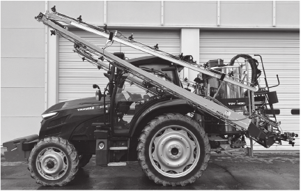
Fig. 1. Tractor-mounted boom sprayer for large-scale crop farming.
A boom sprayer consists of a tractor-mounted or self-propelled vehicle equipped with a long horizontal boom along which multiple spray nozzles are arranged at regular intervals to uniformly apply pesticides to crops. The boom height above the crop canopy must be maintained within a narrow range to ensure uniform application and to minimize spray drift.
Although increasing the boom length contributes to operational efficiency, it also causes significant vertical oscillations of the boom tips owing to field surface unevenness and tractor rolling, resulting in fluctuations in the boom height. Consequently, spray drift and non-uniform applications occur, posing severe problems from the perspective of precision crop protection. Notably, BSs are the most frequently used agricultural machinery for crop protection in arable farming and represent standard equipment in large-scale fields 1.
However, the operator’s ability to visually monitor the tips of booms several tens of meters is limited, making it difficult to maintain a proper spraying height over extended periods. Consequently, stable operation often requires highly skilled operators, imposing a considerable burden on large-scale crop farming. Thus, automated systems to maintain a constant boom height are increasingly required, which is expected to significantly reduce operator workload while improving application accuracy.
In Japan, the “Strategy for Sustainable Food Systems, MIDORI” has been established to reduce environmental impact and achieve sustainable agricultural production. This strategy sets a numerical target of reducing the risk-weighted use of chemical pesticides by 50% by 2050 2.
Spray drift is known to be influenced by various factors such as boom height, nozzle characteristics, and meteorological conditions, with numerous studies reporting that drift increases markedly as boom height increases [3–5]. This relationship has also been confirmed in landscape-scale modeling studies 6,7, highlighting that precise boom-height control is essential for drift reduction. Nevertheless, mechanically maintaining a constant boom height is challenging, because booms undergo vibrations and vertical oscillations during operation.
To address this problem, automated boom-height control systems have been developed overseas and are being increasingly commercialized. For instance, systems such as NORAC UC5 and Raven AutoBoom have been installed on agricultural machinery to automatically control boom elevations [8–10]. However, ultrasonic sensors, which are widely employed in these systems, exhibit considerable variation in detection accuracy depending on the crop type and growth stage. Significant errors have been reported to occur, particularly in sparse and erect crops, such as wheat 11. Moreover, when multiple ultrasonic sensors are installed simultaneously, crosstalk occurs, which is a major cause of erroneous distance measurements 12,13. Environmental factors, such as temperature, humidity, wind, and multiple reflections, have also been shown to markedly deteriorate distance accuracy 14. Thus, ultrasonic sensing is constrained by the usage conditions, and it is necessary to develop alternative sensing technologies based on different principles to expand the options for boom-height control. Although new technologies such as LiDAR have been proposed 15, their adoption encounters cost and operational limitations, further emphasizing the need for the diversification of sensor technologies.
In response, we focused on the development of a boom-height detection device using position-sensitive detectors (PSDs), which are widely applied in various everyday technologies such as optical tracking and distance measurement 16,17. By leveraging this versatile sensor technology, this study aimed to explore its potential for agricultural applications. Previous studies have clarified the detection characteristics of PSD-based sensing for four major arable crops in Hokkaido and reported prototype modules utilizing PSDs [18–20]. Furthermore, a device incorporating multiple PSDs was developed, demonstrating stable measurement performance; however, problems such as optical interference and system enlargement remained.
The objective of this study was to develop a compact PSD-based boom-height detection device that achieves both interference avoidance and miniaturization and to integrate it with a hydraulic control mechanism as a fundamental automatic boom-height control system. Although the control evaluation was limited to basic step-response tests, this paper highlights the effectiveness of the newly developed PSD-based sensor and establishes a baseline system that provides a foundation for future advanced control methods.
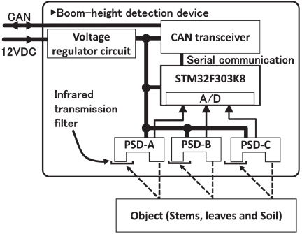
Fig. 2. Operating principle of the PSD-based boom-height detection device.
2. Materials and Methods
2.1. PSD-Based Boom-Height Detection Device
2.1.1. Structure of the Detection Device
An overview of the PSD-based boom-height detection device is shown in Fig. 2. The boom-height detection device is equipped with three PSDs to measure the boom height above the crop canopy in a non-contact manner. The measurement range of the tested PSD (Sharp, GP2Y0A02YK) is 20–150 cm. It irradiates the target object with infrared light at a wavelength of \(850\pm 70\) nm and detects the position of the reflected light on the sensor surface to calculate the distance based on triangulation. The projected spotlight from the PSD is reflected by the crop canopy; however, in some scenarios, it penetrates the foliage and detects the ground. To ensure stable detection regardless of crop morphology, we employed multiple PSDs.
The detection unit consists of three PSDs: an infrared transmission filter (cutoff wavelength: 860 nm) to reduce the disturbances caused by sunlight, a microcontroller (STM32F303K8) for signal processing, and a CAN communication board. The output voltages obtained from the PSDs are digitized using a 12-bit A/D converter and transmitted via the CAN at a sampling frequency of 40 Hz and a communication speed of 250 Mbps.
Based on previous results 20, the simultaneous processing of distance data from three PSDs improves the robustness against abrupt detection failures caused by crop defects or sparse canopies. Therefore, three PSDs were adopted as a practical minimum configuration.
Mechanical considerations also influence sensor-integration design. To minimize the added mass and vibration on lightweight tractor-mounted booms, we integrated the three PSDs into a single compact unit, which also simplifies installation and maintenance.
2.1.2. Prototype Improvements for Interference Avoidance
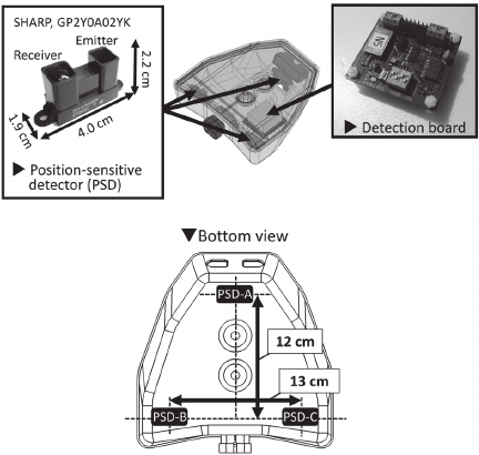
Fig. 3. Overview of the prototype device (Type 1).
In a previous study, we developed a boom-height detection device with three PSDs oriented vertically toward the ground 18. However, when PSDs were placed in close proximity, mutual infrared interference occurred, leading to erroneous operations. To avoid this, we positioned one PSD at the front and two at the rear; however, this arrangement made miniaturization of the system difficult. The prototype is shown in Fig. 3. These results highlight that further improvement requires a design that enables the sensors to be placed closer together while suppressing optical interference.
In practical boom sprayer applications, multiple detection devices are installed along the boom rather than at each nozzle. The present device was developed assuming a boom length of approximately 30 m, with four detection devices installed, i.e., two on each side of the boom. This installation configuration is consistent with that of conventional ultrasonic boom-height sensors. For shorter booms of approximately 20 m, detection devices are commonly installed near both ends of the boom.
2.1.3. Detection Principle and Signal Processing Algorithm
The three measured distances were processed using a program implemented in the microcontroller and integrated into a single detection value. As the data from the three PSDs may include distances corresponding to the ground or intermediate foliage as well as crop tops, a two-step algorithm was implemented 19,20. First, the minimum-value process selects the smallest value for each sample, which reflects the highest part of the crop canopy. Second, the seven most recent minimum values were stored, and their medians were selected to eliminate outliers. This “minimum-value plus median” algorithm suppresses sudden erroneous detections and provides a stable measurement of boom height near the crop canopy.
2.2. Automatic Boom Height Control System
2.2.1. Specifications of the Test Boom Sprayer
The BS used in this study was a mounted sprayer (Toyo Agricultural Machinery, TMS1521DHFRZ) with an effective spray width of 21 m and a tank capacity of 1,500 L. The BS consisted of five boom sections: a center boom flanked on both sides by two articulated boom sections (Fig. 4).
Ten hydraulic cylinders were installed on the boom, allowing deployment and retraction using the hydraulic fluid supplied from the hydraulic tank. Among these cylinders, those primarily responsible for adjusting the boom height during spraying were the cylinders on the left and right first and second booms, as well as the central boom lift and tilt cylinders, which adjusted the inclination of the entire boom. Hydraulic power and the power for spraying operations were transmitted from the tractor’s power takeoff shaft, which is a standard mechanical output device that transfers engine power to the attached implements, to the sprayer’s pump via a universal joint.
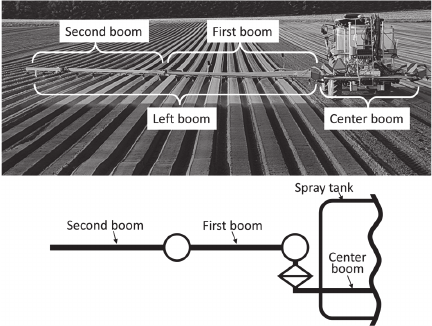
Fig. 4. Boom articulation mechanism of the boom sprayer (back view).
2.2.2. Hydraulic Circuit and Control Components
The hydraulic circuit was equipped with solenoid valves (Bosch Rexroth, EDBZ-VR-AB) to switch the hydraulic fluid flow. These are double-solenoid spool valves with three positions and four ports. Because the solenoid valve operates only in a binary (open/closed) manner and cannot finely regulate the flow, a needle valve was installed in the hydraulic circuit of the first boom lift cylinder to allow for fine manual adjustment of the flow.
The automatic boom-height control system consists of a PSD-based detection device, an electronic control unit, solenoid valves, and hydraulic cylinders. The connection shown in Fig. 5 is a simplified schematic representation of the hydraulic system provided to illustrate the control architecture rather than to depict the detailed hydraulic circuit.
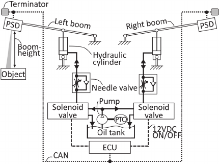
Fig. 5. Simplified schematic of the hydraulic control system of the boom sprayer.
2.2.3. Control Algorithm
In this study, control was applied to the vertical movement of the first left and right boom sections to simplify the control design. The control algorithm calculated the error \(E\) as the difference between the target height \(t\) and the measured height \(y\). All variables in this equation are expressed in centimeters (cm).
When the error exceeds a predefined deadband (e.g., \(-10\le E\le 10\)), the solenoid valves are actuated. A positive error results in a boom elevation, whereas a negative error lowers the boom. The introduction of a deadband prevented excessive actuator operation and ensured control stability.
Because the solenoid valves operate in a 100% open/closed manner and cannot continuously regulate the flow, a timer function was used to adjust the valve operation time within the range of 0.1–0.5 s. This enabled the displacement control of the boom. From the BS specifications, the boom-tip displacement was estimated to be approximately 10 cm per 0.1 s of valve operation. Based on this characteristic, the operational time was set according to the desired displacement.
In addition to this basic on–off control, an enhanced automatic control algorithm was implemented.
Specifically, the valve actuation pulse width was varied according to the magnitude of the height error, resulting in variable on/off actuation behavior.
To compensate for the insufficient upward displacement caused by the self-weight of the boom, we extended the valve-opening duration during the upward motion when residual errors persisted across successive control cycles. This adjustment was implemented using discrete-timing-based logic rather than a continuous integral control formulation.
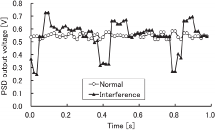
Fig. 6. Comparison of voltage waveforms under interference and normal conditions.
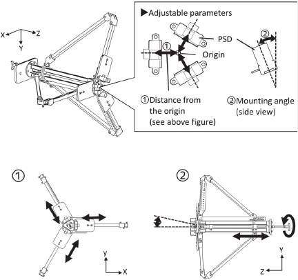
Fig. 7. Angle-adjustable fixture.
3. Experimental Methods
3.1. Interference Test of PSDs
When PSDs are placed in close proximity, the infrared light emitted from one sensor may enter the receiving element of an adjacent sensor, causing optical interference (Fig. 6). This interference introduces noise into the output voltage, thereby preventing accurate distance measurements. Therefore, in boom-height detection devices equipped with multiple sensors, an arrangement that avoids interference is essential.
For the experiment, an angle-adjustable fixture capable of mounting three PSDs was fabricated (Fig. 7). The fixture allowed adjustment of the sensor spacing by sliding the mounting sections and adjusting the mounting angles by rotating a central screw shaft connected to a linkage mechanism. The PSDs were powered using a regulated power supply, and their output voltages were measured using an oscilloscope.
During the experiment, the distance to the target was varied from 20 to 160 cm at 20 cm intervals, and the mounting angle was varied from 0° to 6° at 2° intervals. Center-to-center spacing between sensors was set at 2.5 cm, 3.0 cm, and 4.0 cm. In this study, optical interference was defined as a condition in which the peak-to-peak value increased by more than 0.1 V compared with the non-interference condition.
3.2. Detection Error for Crops
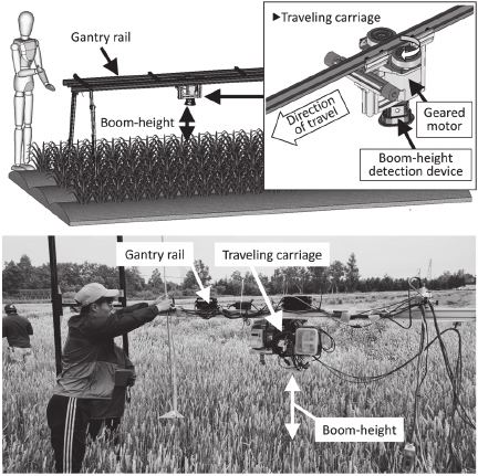
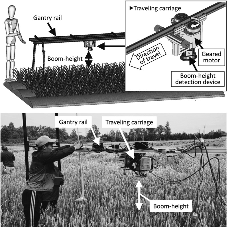
Fig. 8. Detection test for wheat using a traveling carriage.
To evaluate the practical applicability of the proposed boom-height detection device, we conducted detection error tests on field crops. The experiments were performed at the experimental farm of the Obihiro University of Agriculture and Veterinary Medicine, targeting four representative crops: potato, sugar beet, soybean, and wheat.
A portable traveling carriage was fabricated for the experiment (Fig. 8). The carriage consisted of a suspended monorail mechanism that moved at constant speeds along a 4 m horizontal gantry rail installed above the crop field, with the detection device mounted below. The sensor was mounted on a moving cart that traveled along the rail to detect the boom height. Two traveling speeds, 1.0 and 1.5 m/s, were tested to investigate the effect of movement speed on measurement performance. After a 1 m acceleration zone, measurements were taken in the subsequent 1 m evaluation section once the speed was stabilized.
For accuracy evaluation, an acrylic plate was vertically lowered beneath the detection device to contact the crop canopy, and the canopy height was measured manually with a ruler at 10 cm intervals along the travel direction. These measurements were used as the reference values. The detection accuracy was evaluated by calculating the root mean square error between the measured and reference values.
3.3. Operational Test of the Hydraulic Control System
The hydraulic control experiment was conducted by using the right-side first boom of the test sprayer. A container (65 cm in height) was placed beneath the detection device as the target object, and the target boom height was set to 100 cm (Fig. 9). The distance from the boom to ground was measured using an ultrasonic sensor (Pepperl\(+\)Fuchs AG, UC4000-L2-U-V15).
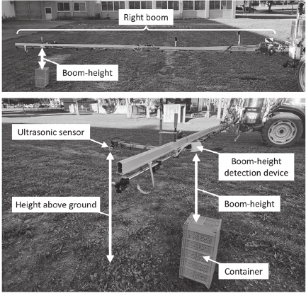
Fig. 9. Experimental setup for the step response test of the automatic boom-height control system.
As described in Section 2.2, the boom-height control program calculates the error as the difference between the target and measured heights. When the error exceeds the deadband, the solenoid valves are actuated for a fixed duration. In this experiment, the valve operating times of 0.5 s for upward motion and 0.4 s for downward motion were set as the maximum actuation durations for a single control action. During the operation, the boom-height error was evaluated at each control cycle, and the solenoid valve was deactivated immediately when the measured height entered the deadband, even if the maximum actuation time had not elapsed. The instant at which the detection device recognized the target object was defined as the input step, and the time required for the boom to reach the target height was recorded as the step response.
The rise time (time from response initiation to 90% of the final value) and fall time (time for the response to decrease from 90% to 10% of the final value) were measured as performance indicators.
This study focused on establishing a baseline sensing and control system. A detailed dynamic analysis under field operation will be addressed in future studies.
4. Experimental Results
4.1. Interference Test of PSDs
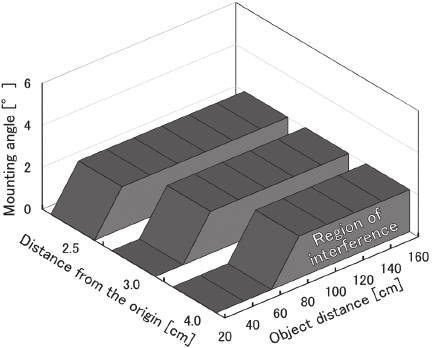
Fig. 10. Interference region based on voltage (shaded area indicates interference).
When optical interference was evaluated using the peak-to-peak values, we determined that interference occurred at object distances of 40, 60, and 80 cm or greater for center-to-center spacings of 2.5, 3.0, and 4.0 cm, respectively, when the mounting angle was 0°. Fig. 10 shows that interference did not occur at mounting angles of 2° or greater, regardless of the object distance or sensor spacing.
However, because the PSD outputs an analog voltage that is inversely related to the measured distance, the same voltage error has a greater impact on the distance accuracy at longer ranges. Therefore, the measurement error after converting the voltage to distance should be evaluated.
For this evaluation, the data from the PSD exhibiting the largest voltage fluctuation among the three sensors were converted from voltage to distance and analyzed. A sixth-order polynomial approximation of the voltage–distance relationship under non-interference conditions was applied to estimate the measurement errors at each object distance. For a precise evaluation, each PSD was calibrated in advance, and the polynomial approximation parameters were obtained.
Because the detection device was designed to be installed above the spray nozzles, the evaluation focused on object distances of 40–100 cm, which correspond to typical boom spray heights of 0–60 cm. Measurement errors converted from voltage to distance showed that at a mounting angle of 2°, errors reached up to 25 cm for a 2.5 cm spacing and nearly 15 cm for a 3.0 cm spacing (Fig. 11). In contrast, at mounting angles of 4° and 6°, the measurement errors were almost identical to those under non-interference conditions and remained below 10 cm. These results indicate that optical interference can be effectively avoided at mounting angles of 4° or greater.
Based on these results, a new prototype device, hereafter referred to as Type 2, was fabricated with PSDs mounted at a center-to-center spacing of 2.5 cm and an outward tilt angle of 6°. Although no interference was observed at either 4° or 6° under the experimental conditions, a tilt angle of 6° was selected to provide a greater safety margin against potential interference under real field conditions, where the crop shape, surface orientation, and reflectance may vary. Excessively large mounting angles are not desirable, as they may slightly reduce the measurable distance range and could increase susceptibility to low-angle sunlight (e.g., early morning or late afternoon), although this effect was not quantitatively evaluated in this study.
This three-dimensional configuration effectively suppressed optical interference while enabling system miniaturization, as illustrated in Fig. 12. Compared with Type 1, in which the triangular area defined by the PSD centers was 7970.95 mm\(^2\), the corresponding area in Type 2 was reduced to 752.97 mm\(^2\), achieving approximately a 90% reduction in size.
4.2. Detection Error for Crops
The detection errors for the four crops are shown in Fig. 13. The mean detection errors of the device were \(-4.6\) cm for potato, \(+2.9\) cm for soybean, and \(-1.8\) cm for sugar beet, respectively, all within \(\pm 5\) cm. In contrast, wheat exhibited a maximum error of \(+7.4\) cm, where the sensor underestimated the actual crop height by detecting the upper leaves instead of the panicles after heading. This suggests the necessity of introducing a “wheat mode” that applies an offset correction corresponding to panicle length. The standard deviations of the crop distance detection errors are summarized in Table 1.
These results indicate that crop-dependent detection errors are primarily governed by canopy morphology and that such errors can be mitigated through crop-specific correction strategies.
4.3. Operational Test of the Hydraulic Control System
The step-response experiment was conducted with the tractor stationary and was intended to evaluate the fundamental response characteristics of the hydraulic control system under controlled conditions rather than the dynamic boom behavior during field operation.
Step response experiments of the automatic boom-height control system demonstrated rise and fall times of 0.95 and 2.41 s, respectively (Fig. 14). During upward motion, the solenoid valve operation was limited to a maximum duration of 0.5 s. However, the residual offset from the target height was mainly caused by the deadband implemented in the control logic, rather than by the valve operation time limit. In contrast, during the downward motion, the short valve operation time restricted the displacement. Nevertheless, the response was stable and no excessive overshoots were observed.
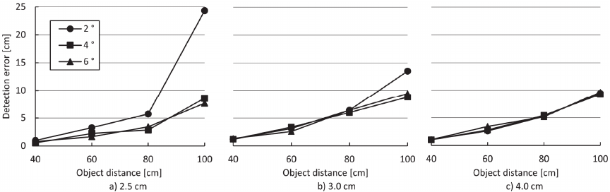
Fig. 11. Detection error relative to distance from the origin.
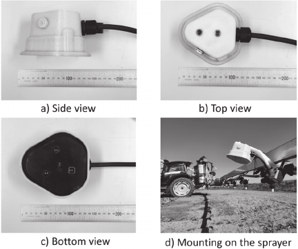
Fig. 12. Appearance of the improved prototype device (Type 2) with a mounting angle of 6°.
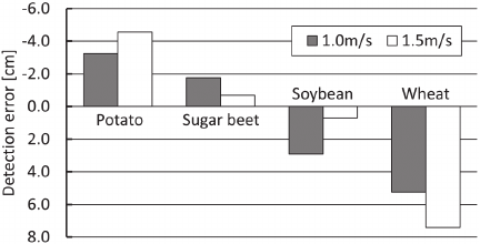
Fig. 13. Detection error of four field crops.
Table 1. Standard deviation of crop distance detection error at two travel speeds.

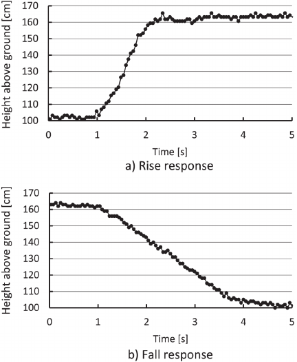
Fig. 14. Step response of the automatic boom height control system.
These results indicate that although the system operated stably, the simple on–off control scheme prevented precise adjustment of the boom height to the target position. As agricultural boom sprayers are long and flexible structures that undergo significant deflection during operation, a more sophisticated control system should be developed to achieve accurate and responsive height regulation.
These results suggest that PSD-based sensing provides a generally applicable and robust approach for boom-height detection under practical field conditions, although further analysis is required to generalize the method across different growth stages and dynamic operating conditions.
5. Conclusions
In this study, a compact PSD-based boom-height detection device was developed and integrated into an automatic boom-height control system for long-boom sprayers (20–30 m class). By arranging three PSD sensors at a 6° outward tilt in a three-dimensional configuration, the device effectively reduced optical interference while achieving miniaturization. Field tests demonstrated that the system could measure canopy heights with errors within \(\pm 5\) cm for potato, soybean, and sugar beet. However, wheat showed larger detection errors (up to \(+7.4\) cm), indicating the need for crop-specific corrections. Step response experiments were conducted using a 65-cm-height container placed beneath the boom, with the target boom-height set to 100 cm. The hydraulic control system achieved rise and fall times of 0.95 s and 2.41 s, respectively, without overshoot.
Overall, the results confirm the feasibility of using PSD-based sensors for boom-height control and demonstrate the construction of a baseline automatic system using PSD-based data, while highlighting the need for more advanced control methods to accommodate the dynamic characteristics of long and flexible agricultural booms. Furthermore, this technology represents an elemental approach that can be applied not only to automation but also to unmanned crop protection systems when integrated with robotic tractors.
Acknowledgments
This study was conducted as a joint project with the Toyo Agricultural Machinery Manufacturing Co., Ltd., which kindly lent experimental equipment and offered technical support for hydraulic control. This work was supported by JSPS KAKENHI (Grant Number JP21K14944).
- [1] É. F. Reynaldo, T. M. Machado, L. Taubinger, and D. de Quadros, “Vertical and horizontal oscillation of three models of self-propelled boom sprayers,” Revista Brasileira de Engenharia Agrícola e Ambiental, Vol.20, No.10, pp. 941-945, 2016. https://doi.org/10.1590/1807-1929/agriambi.v20n10p941-945
- [2] Ministry of Agriculture, Forestry and Fisheries (MAFF), “MAFF publishes 2021 status of Japan Green Food System Strategy targets,” 2023.
- [3] A. Nordby and R. Skuterud, “The effects of boom height, working pressure and wind speed on spray drift,” Weed Research, Vol.14, No.6, pp. 385-395, 1974. https://doi.org/10.1111/j.1365-3180.1974.tb01080.x
- [4] D. Nuyttens, I. K. A. Zwertvaegher, and D. Dekeyser, “Spray drift assessment of different application techniques using a drift test bench and comparison with other assessment methods,” Biosystems Engineering, Vol.154, pp. 14-24, 2017. https://doi.org/10.1016/j.biosystemseng.2016.10.010
- [5] X. Pan, S. Yang, Y. Gao, Z. Wang, C. Zhai, and W. Qiu, “Evaluation of spray drift from an electric boom sprayer: Impact of boom height and nozzle type,” Agronomy, Vol.15, No.1, Article No.160, 2025. https://doi.org/10.3390/agronomy15010160
- [6] H. J. Holterman, “Modelling spray drift from boom sprayers,” Computers and Electronics in Agriculture, Vol.19, No.1, pp. 1-22, 1998. https://doi.org/10.1016/S0168-1699(97)00018-5
- [7] M. D. Fuchs, S. Gebler, and A. Lorke, “The droplet and atmospheric dispersion drift (DAD-drift) model – A modular approach for estimating spray drift at the landscape scale,” Environmental Research, Vol.271, Article No.121104, 2025. https://doi.org/10.1016/j.envres.2025.121104
- [8] A. Herbst, H.-J. Osteroth, and H. Stendel, “A novel method for testing automatic systems for controlling the spray boom height,” Biosystems Engineering, Vol.174, pp. 115-125, 2018. https://doi.org/10.1016/j.biosystemseng.2018.07.011
- [9] J. Li, Z. Nie, Y. Chen, D. Ge, and M. Li, “Development of boom posture adjustment and control system for wide spray boom,” Agriculture, Vol.13, No.11, Article No.2162, 2023. https://doi.org/10.3390/agriculture13112162
- [10] T. A. Burgers, J. D. Gaard, and B. J. Hyronimus, “Comparison of Three Commercial Automatic Boom Height Systems for Agricultural Sprayers,” Applied Engineering in Agriculture, Vol.37, No.2, pp. 287-298, 2021. https://doi.org/10.13031/AEA.14346
- [11] X. Zhao, C. Zhai, S. Wang, H. Dou, S. Yang, X. Wang, and L. Chen, “Sprayer boom height measurement in wheat field using ultrasonic sensor: An exploratory study,” Frontiers in Plant Science, Vol.13, Article No.1008122, 2022. https://doi.org/10.3389/fpls.2022.1008122
- [12] H. Y. Jeon, H. Zhu, R. Derksen, E. Ozkan, and C. Krause, “Evaluation of ultrasonic sensor for variable-rate spray applications,” Computers and Electronics in Agriculture, Vol.79, No.1, pp. 213-221, 2011. https://doi.org/10.1016/j.compag.2011.08.005
- [13] L. Liu, R. Guo, and J. Wu, “Design of a fast echo matching algorithm to reduce crosstalk with Doppler shifts in ultrasonic ranging,” Measurement Science and Technology, Vol.28, Article No.025103, 2017. https://doi.org/10.1088/1361-6501/28/2/025103
- [14] A. Rudyk, A. Semenov, S. Baraban et al., “Influence of environmental factors on the accuracy of the ultrasonic rangefinder in a mobile robotic technical vision system,” Electronics, Vol.14, No.7, Article No.1393, 2025. https://doi.org/10.3390/electronics14071393
- [15] H. Dou, “Low-cost LiDAR-based spray boom height measurement system,” Sensors, Vol.21, No.6, Article No.1954, 2021. https://doi.org/10.3390/s21061954
- [16] Y. Do and J. Kim, “Infrared range sensor array for 3D sensing in robotic applications,” Int. J. of Advanced Robotic Systems, Vol.10, No.4, Article No.193, 2013. https://doi.org/10.5772/55896
- [17] P.-L. Kuo, C.-H. Wang, H.-J. Chou, and J.-S. Liu, “A real-time hydrodynamic-based obstacle avoidance system for non-holonomic mobile robots with curvature constraints,” Applied Sciences, Vol.8, No.11, Article No.2144, 2018. https://doi.org/10.3390/app8112144
- [18] A. Fujimoto, T. Satow, T. Makino, and K. Funabiki, “Development of boom height measurement module with PSD sensor,” Proc. of the 9th Int. Symp. on Machinery and Mechatronics for Agricultural and Biosystems Engineering, pp. 307-312, 2018.
- [19] A. Fujimoto, T. Satow, and K. Funabiki, “Development of a boom height measurement device with position-sensitive detectors,” J. of the Japanese Society of Agricultural Machinery and Food Engineers, Vol.84, No.5, pp. 332-338, 2022 (in Japanese).
- [20] A. Fujimoto, T. Satow, and M. Akimoto, “Development of a boom-height detection device using position-sensitive detectors – Evaluation of detection accuracy for four major field crops in Hokkaido –,” J. of the Japanese Society of Agricultural Machinery and Food Engineers, Vol.87, No.4, pp. 378-385, 2025 (in Japanese).
This article is published under a Creative Commons Attribution-NoDerivatives 4.0 Internationa License.