Development Report:
Development of a Hammer-Knife Type Mower
Hiroto Tanaka and Hiroshi Kobayashi
Department of Mechanical Engineering, Graduate School of Engineering, Tokyo University of Science
6-3-1 Niijuku, Katsushika-ku, Tokyo 125-8585, Japan

Regular mowing operations are required on ridge paths; however, ridge paths are often narrow and sloped, making mechanization necessary from the perspectives of work efficiency and safety. In this study, the performance of currently available commercial mowers was first organized and analyzed, and a conceptual design of a mower specialized for ridge-path operations was proposed. First, a remote-control operation system was adopted to reduce the operator’s workload. Next, a hybrid drive system was employed in which an engine generates electricity to drive electric motors. In addition, a hammer-knife mechanism, which provides high durability and excellent mowing performance, was adopted as the mowing mechanism. Furthermore, in order to enable operation in narrow environments such as ridge paths, the machine width was set to approximately 600 mm. To evaluate the performance of the developed machine, traveling tests, mowing performance tests, and fuel consumption tests were conducted. In the mowing performance tests, evaluations were carried out under different cutting-height conditions, and a high mowing performance of over 96% on average was confirmed under the cutting height condition of 80 mm. In contrast, under the cutting height condition of 180 mm, grass was pressed down beneath the machine body during traveling and did not reach the cutting blades, resulting in a tendency for approximately 15% of the grass to remain uncut on average. In addition, turning tests under slope conditions were conducted on both asphalt and grass surfaces. The results showed that although sufficient performance was not obtained on the asphalt surface under the slope angle condition of 20°, stable traveling and turning performance were confirmed on the grass surface, which simulates actual ridge-path environments. Furthermore, the evaluation of fuel consumption characteristics demonstrated that the developed machine is capable of long-duration continuous operation. From these results, it was confirmed that the developed machine has sufficient adaptability to narrow environments such as ridge paths and exhibits good traveling and mowing performance.
Mower designed for narrow-width operation
1. Introduction
Research on the robotization and automation of mowing operations has been widely conducted both domestically and internationally. In this section, the objective is to clarify the design concept of the system developed in this study through a comparison with existing products.
Table 1. Features of off-the-shelf products.

1.1. Drive Systems of Mowers
The drive systems of mowing machines currently available on the market can be broadly classified into four types: manual (push-type), electric (EV), engine-powered, and hybrid, each of which has its own advantages and disadvantages.
First, manual push-type mowers a,b have the simplest structure, are inexpensive, and require almost no maintenance costs. Because they generate little noise and impose a low environmental burden, they are suitable for use in home gardens and small yards. However, their performance depends heavily on the physical strength of the operator, making them unsuitable for large areas, and prolonged use results in significant fatigue.
Next, electric (EV) mowers c,d are powered by batteries and are highly valued for their low environmental impact. They produce no exhaust gas and operate quietly, making them convenient for use in residential areas, schools, and around hospitals. However, their operating time is limited by battery capacity, rendering them unsuitable for long-duration continuous operation. In addition, battery replacement and charging infrastructure are required, which tends to increase running costs.
Engine-powered mowers [e–i] have long been the mainstream type and are capable of high output and long-duration operation. They are widely used in agricultural fields, large parks, and road maintenance. A major advantage is that operation can be resumed immediately by refueling, resulting in few constraints on operating time. On the other hand, they impose a high environmental burden due to noise and exhaust emissions, and their heavy weight makes handling difficult. Furthermore, engine maintenance and fuel costs increase the management burden.
Finally, hybrid mowers [j–l] are a newer type that combines an engine and an electric motor. While retaining the high output and long operating time of an engine, they take advantage of the quietness and smooth startup characteristics of electric motors, and are expected to achieve higher efficiency. Improvements in fuel economy and overall energy efficiency are also anticipated. However, their complex structure leads to higher manufacturing and sales costs, requiring a certain level of initial investment. In addition, market penetration remains limited, and maintenance systems are often not yet fully established.
Table 1 summarizes the main characteristics of mowing machines that are currently in widespread use.
1.2. Types of Cutting Blades
The cutting blades used in mowing machines can be broadly classified into two types: rotary knife type and hammer knife type, each of which has distinct characteristics.
The rotary knife type 1 cuts grass by rotating multiple horizontally arranged blades at high speed. This method provides a relatively clean finish and enables uniform mowing even in areas where turf grass and weeds are mixed. Owing to its simple structure and light weight, it is easy to handle and can be manufactured at low cost. However, because the cutting blades are located beneath the machine body, the grass is first pressed down by the crawler tracks and then cut, which makes this system less suitable for tall weeds or hard stems. In addition, due to the structural constraint that the blades must fit within the crawler width, the cutting width is narrower than the overall width of the machine.
In contrast, the hammer knife type employs numerous blades mounted on a rotating shaft, which are swung outward by centrifugal force to shred the vegetation. This method can finely pulverize tall weeds, hard stems, and even thin branches, eliminating the need for post-mowing collection or processing. The blades are designed to swing away when they encounter obstacles, resulting in excellent durability. However, compared with the rotary knife type, the structure is more complex and heavier, leading to reduced mobility.
In summary, the rotary knife type is lightweight and provides a good finish but has limitations in durability and the range of vegetation it can handle, whereas the hammer knife type offers powerful and versatile cutting performance but tends to be heavier and more expensive. Accordingly, the appropriate blade type is selected depending on the intended application and operating environment.
1.3. Development Policy
To date, numerous studies and developments of mowers intended for mowing operations on farm ridges have been reported 2,3,4,5,6,7,8. However, most of these efforts have been limited to prototype machines or investigations conducted under specific conditions, and at present there are no commercially available models that have been productized based on designs emphasizing practical usability. In particular, it has been difficult to simultaneously satisfy requirements such as operation under narrow ridge conditions, safety on sloped terrain, and reduction of the physical burden on operators, and no sufficiently comprehensive solution has yet been presented. Therefore, this study aims to develop a product specialized for mowing operations on farm ridges by consolidating the knowledge reported to date.
First, from the viewpoint of reducing operator workload, this study ultimately aims for autonomous driving 9,10,11,12,13,14,15; however, as an initial step, a model that can be operated remotely by a handheld controller is considered.
Next, the drive system of the mower is discussed. To maintain high operational efficiency, the authors considered an engine-based system to be preferable to an EV system, which suffers from downtime due to battery charging, because an engine system allows immediate restart simply by refueling. In addition, from the viewpoint of weight reduction, motor-driven locomotion is preferable to a conventional engine-driven system that requires a reduction gearbox to control traveling speed. Accordingly, this study proposes a novel hybrid mechanism 16,17,18 in which the engine is used solely for power generation, while both the rotation of the hammer knives and the traveling drive are fully powered by electric motors.
The next consideration is the type of cutting blade. When assuming use on farm ridges with a width of approximately 800 mm, the overall machine width must be limited to about 600 mm, and crawler tracks are indispensable for achieving stable locomotion 19,20,21,22,23. Therefore, to secure a sufficient cutting width, a hammer knife mechanism was adopted. This configuration eliminates the need to press down vegetation before cutting, thereby reducing the power required for the drive motors.
Finally, detailed specifications are determined. Based on interviews with users of previously developed mowers and industry stakeholders, models with a traveling speed of approximately 1.4 km/h have been found to offer high usability, and many commercially available products target this speed. Accordingly, this study also sets this value as the target traveling speed.
In summary, the specifications of the mower developed in this study are as follows:
-
Remote operation by a handheld controller.
-
Adoption of a hybrid drive system.
-
An overall machine width of approximately 600 mm.
-
Adoption of a hammer knife cutting mechanism.
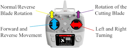
Fig. 1. Operation method.
2. Overview of the System
This section describes the configuration and individual mechanisms of the ridge-specialized mower developed in this study.
2.1. Remote Control via Transmitter
As shown in Fig. 1, the system is controlled by remote operation using a transmitter. Operation commands from the transmitter are transmitted to the control system via a receiver, which in turn actuates each drive subsystem. For operation, the left joystick is used to control forward and backward motion, while the right joystick is used to control left and right turning. In addition, switches located on the upper part of the transmitter allow the operator to start and stop the rotation of the cutting blades.
2.2. Overall Configuration
Figure 2 shows the external appearance of the system and the configuration of its main mechanisms. The mower consists of the following principal subsystems:
-
(A)
Traveling mechanism.
-
(B)
Mowing mechanism.
-
(C)
Power control mechanism.
-
(D)
Power generation mechanism.
-
(E)
Cutting height adjustment mechanism.
Each mechanism functions independently while operating in coordination with the others, thereby enabling stable locomotion and mowing operations in ridge environments.
2.3. Traveling Mechanism
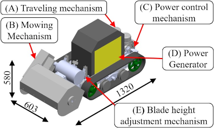
Fig. 2. Overall view of the system.
This section describes the traveling mechanism adopted in the mower and the specifications of the drive motors.
The traveling speed was set to 0.40 m/s (1.4 km/h) with reference to commercially available mowers. Considering stable operation on farm ridges, excessive high-speed travel was intentionally avoided.
The system employs a crawler-type traveling mechanism, with a crawler wheel diameter of \(D=200\) mm. Under this condition, the wheel rotational speed \(n\) [rps] required to achieve the specified traveling speed can be calculated using Eq. \(\eqref{eq:eq1}\):
Here, \(v\) denotes the traveling speed [m/s].
To drive the crawler wheels at the specified traveling speed, a wheel rotational speed of 37.5 rpm is required. Accordingly, a drive motor with a rated rotational speed of 50 rpm was selected, and the required rotational speed was achieved by setting the sprocket tooth ratio to \(3:4\).
Next, the power required for traveling is calculated. Let the resistance coefficient be \(\mu\), the slope angle be \(\phi\) [°], the vehicle mass be \(M\) [kg], and the gravitational acceleration be \(g\) [m/s\(^2\)]; then the required power \(W\) [W] can be expressed by Eq. \(\eqref{eq:eq2}\):
From Eq. \(\eqref{eq:eq2}\), the required driving power during slope operation was calculated to be 650 W or more. Based on this result, this study employs two 400 W DC brushless motors, one on each side, securing a total driving power of 800 W. For the traveling motors, DC brushless motors with a rated output of 400 W and a rated rotational speed of 50 rpm were selected, with a rated voltage of DC 24 V. By adopting independent left–right drive, both straight-line travel and turning maneuvers are realized. The traveling motors used are NISSEI models VHLC28L-50N400L2A and VHLC28R-50N400L2A.
Finally, in order to prioritize traveling stability on farm ridges, a crawler-type traveling mechanism was adopted. For the crawler mechanism, the crawler unit of the ATEX carrier vehicle “XG350” was used. To facilitate crawler installation/removal and tension adjustment, an adjustment bolt ((A) in Fig. 3) is used to push out the idler adjustment section ((B) in Fig. 3), enabling crawler tension adjustment. In addition, by providing track rollers ((C) in Fig. 3), the structure ensures stable ground contact of the crawler.
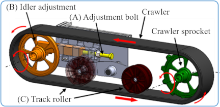
Fig. 3. Drive part.
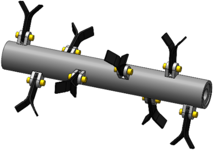
Fig. 4. Hammer knife.
2.4. Mowing Mechanism
In this system, a hammer-knife mechanism was adopted as the mowing mechanism. The hammer-knife system cuts and shreds grass by utilizing centrifugal force generated by the high-speed rotation of multiple blades mounted on a rotating shaft.
The mowing mechanism consists of commercially available hammer knives mounted on a custom-fabricated rotating shaft. Considering versatility and availability, widely used replacement blades manufactured by Kyoeisha Shibaura Inc. were employed.
The arrangement of the hammer knives was designed in a helical configuration to distribute cutting loads evenly (Fig. 4). In addition, the layout was designed with consideration of dynamic balance in order to suppress vibration during rotation.
By rotating these blades at high speed, the developed system achieves high mowing performance despite its compact size.
Furthermore, the hammer knives have a structure that allows each blade to pivot around the rotating shaft when it comes into contact with an obstacle (Fig. 5), thereby reducing blade breakage and damage. This characteristic improves durability and maintainability, which is expected to lead to a reduction in operational costs. In addition, the cut grass is processed into finely shredded pieces, resulting in a lower risk of grass scattering and providing advantages from a safety perspective.
Moreover, the developed system is equipped with a mechanism that allows the rotation direction of the hammer knives to be switched between forward and reverse rotation. This function enables adjustment of mowing characteristics according to grass species, grass density, and terrain conditions, thereby enhancing adaptability to a wide range of operating environments. This mechanism is realized by utilizing the characteristic of the employed motor (the specifications of which are described later), which allows the wiring connections to be switched through simple switch operation (Fig. 6).
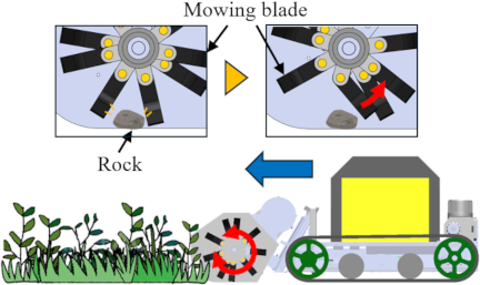
Fig. 5. Structure of the mowing blade.
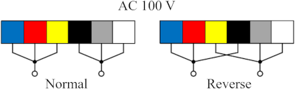
Fig. 6. Motor wiring for normal and reverse rotation.
Next, the driving power required for rotation of the cutting blades is estimated. In a hammer knife mower, the required power for the blade rotation system can be expressed as the sum of the power needed for cutting and shredding the grass and the idling losses of the rotating components. Previous studies 24,25,26 have also reported that the power demand increases in proportion to the grass feed rate (i.e., the working width and forward speed) and includes a loss component inherent to the rotating system.
In this study, as an estimate at the design stage, the specific energy method is employed, and the required power of the blade rotation system, \(P_{\mathrm{req}}\), is expressed by Eq. \(\eqref{eq:eq3}\):
Here, \(P_{0}\) represents the loss power when the cutting blades are rotating without load, and \(P_{\mathrm{cut}}\) denotes the power required for cutting and shredding the grass. The power required for grass processing, \(P_{\mathrm{cut}}\), can be expressed by Eq. \(\eqref{eq:eq4}\) as the product of the specific energy required per unit mass, \(E_\mathrm{s}\) [J/kg], and the grass mass flow rate processed per unit time, \(\dot{m}\) [kg/s]:
The grass mass flow rate \(\dot{m}\) is given by Eq. \(\eqref{eq:eq5}\) using the areal density of grass \(\rho_{\mathrm{A}}\) [kg/m\(^2\)], the cutting width \(w\) [m], and the forward speed \(v\) [m/s]:
From Eqs. \(\eqref{eq:eq4}\) and \(\eqref{eq:eq5}\),
The design conditions assumed for the blade rotation system in this study are as follows: cutting width \(w = 0.54\) m, forward speed \(v=1.4\) m/s, total number of blades: 18, and power transmission efficiency \(\eta = 1\).
For the grass conditions and loss components, a relatively dense grass field was assumed as a design-stage estimate, with \(\rho_{\mathrm{A}} = 1.8\) kg/m\(^2\), \(E_{\mathrm{s}} = 400\) J/kg, and \(P_{0} = 150\) W. Under these assumptions, the required power for the blade rotation system was calculated to be \(P_{\mathrm{req}} = 695\) W. Accordingly, this study adopts the SCL-MR750 motor manufactured by Murai Kiki Seisakusho as the blade drive motor. The motor has a rated output of 750 W, which satisfies the power requirements of the blade rotation system within the range of grass and operating conditions assumed in this study. The rotational speed of mowing blades required for grass-cutting operations is generally considered to be approximately 2000–3000 rpm. Since the rated rotational speed of the motor used in this study is 1440 rpm, a pulley speed-increasing ratio of 1.5 was applied, resulting in an actual blade rotational speed of 2160 rpm.
2.5. Power Control Mechanism
The mower developed in this study employs a hybrid power supply system in which the primary power source is AC electricity generated by an onboard engine-driven generator. This AC power is converted, via a converter, into a DC voltage suitable for driving the motors.
The AC 100 V output from the generator is first converted to DC by a rectifier circuit and then stepped down to 24 V by a converter, which also regulates the output voltage to remain constant under varying load conditions. Since the total power required by the drive motors is 800 W, and considering a conversion efficiency of 80%, a 1500 W-rated converter was selected.
2.6. Power Generation Mechanism
In this system, a converter supplies up to 1500 W of electric power and drives a blade motor with a rated output of 750 W. To satisfy these power demands, it is necessary to select a generator with sufficient output margin. Accordingly, this study adopts a generator manufactured by Aceup Energy with a rated output of 3.2 kVA and a maximum output of 3.5 kVA.
The generator is equipped with a four-stroke gasoline engine with a displacement of 149 cc and a weight of 23 kg. Owing to its relatively light weight and good portability, it is easy to handle even during mowing operations on uneven terrain. The fuel tank capacity is 5 L (fuel type: unleaded gasoline), enabling approximately 3.5 hours of continuous operation at maximum load.
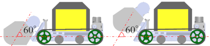
Fig. 7. Lowering angle.
2.7. Cutting Height Adjustment Mechanism
In this machine, a ball screw and linear guides are employed as the lifting mechanism for the cutting blade unit, allowing the cutting height to be adjusted freely according to operating conditions and vegetation. An operating handle is attached to the end of the ball screw, and by rotating the handle, the blade unit can be raised and lowered smoothly and reliably. The adjustable cutting height range is 0–180 mm, enabling adaptation to a wide variety of working environments.
However, since this mechanism is located at the front of the machine, vertical movement of the blade unit during height adjustment would cause a significant shift in the vehicle’s center of gravity, potentially reducing traveling stability—particularly on downhill slopes due to forward load concentration. To address this issue, the lifting direction of the blade unit was inclined at 60° with respect to the horizontal plane (Fig. 7). This configuration suppresses center-of-gravity displacement during cutting height adjustment and improves traveling stability during operations on sloped terrain.

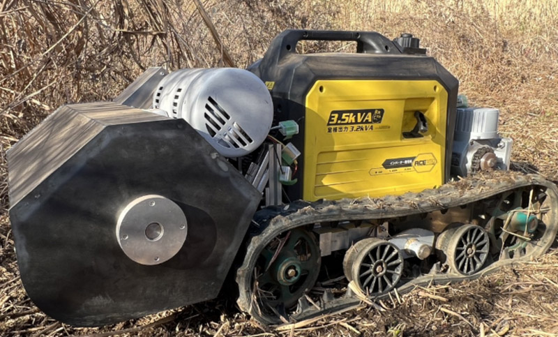
Fig. 8. Developed mowing machine.
3. Traveling Experiments and Discussion
Figure 8 shows the external appearance of the mower developed in this study. This section describes the evaluation of mowing performance, the results and discussion of traveling experiments, fuel consumption characteristics, and future improvements. The total weight of the mower developed in this study is approximately 140 kg. All experimental results presented in this section are based on experiments conducted with five trials (\(N = 5\)).
3.1. Experimental Overview
In this study, experimental evaluations were conducted to verify the effectiveness of the mower developed specifically for farm ridges with a width of 600 mm. The evaluations focused on mowing performance, traveling performance, and fuel consumption characteristics.
The experiments were carried out under conditions simulating actual field environments, and quantitative assessments were performed through comparisons with manual operations as well as evaluations of behavior under sloped terrain conditions.
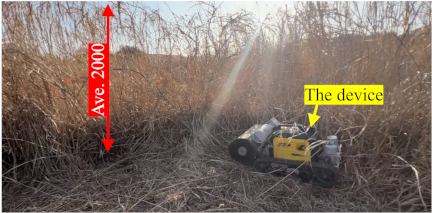
Fig. 9. Grass height in the experiment.
3.2. Evaluation of Mowing Performance
3.2.1. Measurement of Uncut Grass Ratio
The uncut grass ratio was used as an evaluation index of mowing performance 27. Considering usage conditions on farm ridges, the test plot was defined as a rectangular area with a width of 600 mm and a length of 400 mm. The experiments were conducted under conditions simulating actual field environments, and the average grass height of the target vegetation was 2000 mm (Fig. 9).
The uncut grass ratio was measured according to the following procedure:
-
(1)
All grass within the test plot was completely cut manually using a sickle, and the total weight of the collected grass was measured as \(W_{\mathrm{total}}\).
-
(2)
Under the same test plot and identical conditions, mowing was performed using the developed mower.
-
(3)
After mowing, the remaining uncut grass was manually collected, and its weight was measured as \(W_{\mathrm{remain}}\).
-
(4)
The uncut grass ratio \(R\) was calculated using Eq. \(\eqref{eq:eq7}\):
\begin{equation} R = \dfrac{W_{\mathrm{remain}}}{W_{\mathrm{total}}} \times 100 . \label{eq:eq7} \end{equation}
When the test plot (600 mm \(\times\) 400 mm) was completely mowed manually using a sickle, the average grass weight was \(W_{\mathrm{total}} = 1430\) g.
Table 2. Rate of uncut grass.

The cutting height of the developed mower can be adjusted within a range of 0–180 mm, and in this experiment, three conditions—0 mm, 80 mm, and 180 mm—were initially considered. However, when the cutting height was set to 0 mm under uneven field conditions, the cutting blades came into contact with the ground, causing soil to be thrown up, and it was observed that the impact led to the drive motor stopping. Therefore, from the viewpoints of safety and equipment protection, measurements under the 0 mm condition were not conducted, and the evaluation was limited to the 80 mm and 180 mm conditions.
It should be noted that under the 80 mm condition, the actual cutting height locally approached nearly 0 mm due to surface irregularities. Accordingly, this study judged that omitting the 0 mm condition would not hinder the evaluation of mowing performance.
The measured results of the remaining grass weight and the uncut grass ratio are shown in Table 2, and the post-mowing condition is illustrated in Fig. 10.
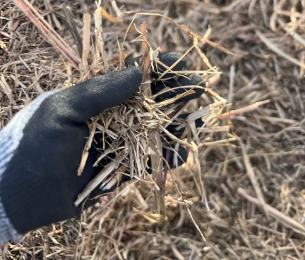
Fig. 10. Post-mowing condition.
Table 3. Mean and standard deviation of remaining grass height.

Table 4. Working time and efficiency.

3.2.2. Evaluation of Cutting Height Variability
To evaluate the uniformity of the cutting height 28, point measurements of the remaining grass height were conducted at multiple locations within the test plot after the mowing operation. A total of 20 measurement points were selected, and the remaining grass height at each point was recorded. From the obtained data, the mean value and standard deviation of the remaining grass height were calculated, enabling a quantitative evaluation of cutting height variability. The measurement results are presented in Table 3.
3.2.3. Evaluation of Work Efficiency
To evaluate work efficiency, the operation time required for manual mowing and for mowing using the developed mower was measured for the same test plot, and the two were compared. The measurement results are shown in Table 4.
For manual work, the measured operation time included the process of collecting the cut grass into bags. In contrast, the developed mower employs a hammer knife mechanism that shreds the grass during mowing, eliminating the need for grass collection. Therefore, the operation time for the developed mower does not include a grass collection process.
Table 5. Traveling speed [m/s].

Table 6. Displacement during turning [mm].

3.3. Evaluation of Traveling Performance
3.3.1. Experimental Conditions
The traveling performance evaluation 29,30,31 was conducted on slopes with inclination angles of 0°, 10°, 15°, and 20°. Under each slope condition, the following three items were measured:
For the evaluation of displacement during turning and slip during slope traversal, experiments were carried out on two types of road surface conditions—asphalt and grass-covered ground—in order to assess slip characteristics on slopes. This approach was adopted to clarify the effects of differences in surface conditions and, by standardizing the test conditions as much as possible, to facilitate performance comparisons with mowers manufactured by other companies.
3.3.2. Traveling Speed
Under each slope angle condition, the test machine was driven straight over a distance of 3 m, and the traveling time was measured to calculate the average traveling speed. The measured results of the average traveling speed for each slope angle are shown in Table 5.
3.3.3. Displacement During Turning
In this experiment, under slope angle conditions of 0°, 10°, 15°, and 20°, the developed machine was made to perform one full turning motion from a stationary position, and the amount of slip generated during the turning operation was measured. The measurement results obtained on the asphalt surface were treated as a reference evaluation under uniform friction conditions, and by comparing them with the results obtained on the grass-covered surface, turning stability under conditions closer to actual field environments was evaluated. The measurement results are shown in Table 6. However, in the test conducted on the asphalt surface at a slope angle of 20°, the test machine slipped down the slope, making it impossible to continue the turning maneuver. Therefore, measurements under this condition could not be performed, and the data for this condition are treated as missing in this study. It has been confirmed that, in actual operating environments, the machine can safely descend by performing a reverse operation. Therefore, this result was judged not to pose any significant obstacle to its practical functionality.
Table 7. Slip distance during slope traverse.

3.3.4. Evaluation of Slip During Slope Traversal
In this experiment, under slope angle conditions of 0°, 10°, 15°, and 20°, the test machine was driven 3 m in the transverse direction across the slope, and the distance \(d\) [mm] by which the machine shifted downward along the slope after traveling was measured. Based on the measured downward displacement, the slip angle \(\theta\) [°] was calculated using Eq. \(\eqref{eq:eq8}\). The calculated slip angles under each condition are presented in Table 7.
3.4. Fuel Consumption Characteristics
3.4.1. Measurement Method
To evaluate fuel consumption characteristics, the test machine was operated continuously with 500 mL of regular unleaded gasoline supplied, and the available operating time until the fuel was completely consumed was measured. The measurements were conducted under conditions assuming steady-state mowing operations, and the obtained available operating time was used as an index of fuel consumption characteristics.
3.4.2. Measurement Results
The measured results of the available operating time with a supply of 500 mL of regular unleaded gasoline are shown in Table 8. The results were converted and organized as operating time per unit amount of fuel.
Table 8. Fuel efficiency.

3.5. Discussion and Future Issues
Under the cutting height condition of 80 mm, the uncut grass ratio exceeded 96%, confirming high mowing accuracy. This is considered to be attributable to the cutting blades reliably capturing grass stems near the ground surface. In contrast, under the 180 mm cutting height condition, it was observed that some grass was pressed down by the underside of the machine during traveling and did not reach the cutting blades, with two to three clumps remaining uncut. As a result, the variability in the amount of remaining grass increased, leading to a larger standard deviation in the remaining grass height.
With regard to work efficiency, under the 80 mm cutting height condition, nearly all grass could be cut in a single pass, eliminating the need for back-and-forth travel. Consequently, the operation time was as short as 12 s, indicating high relative work efficiency. In contrast, under the 180 mm condition, sufficient cutting could not always be achieved in a single pass, and an average of three round trips was required. As a result, work efficiency decreased compared with the 80 mm condition; however, compared with manual mowing, it was confirmed that a substantial reduction in labor was still achieved.
Regarding traveling performance, traveling speeds close to the design targets were generally obtained under all slope angle conditions. On the other hand, in turning tests conducted on the asphalt surface, a relatively large downward displacement was observed. This is considered to be partly due to the large mass of the hammer knife unit installed at the front of the machine, which increases the forward load. In future work, improvements in turning stability will be pursued through weight reduction of the hammer knife unit and optimization of the center-of-gravity layout.
Furthermore, with respect to downward slipping during transverse slope travel, it is considered possible to further suppress this phenomenon by introducing a mechanism that independently controls the rotational speeds of the left and right drive wheels relative to the slope.
As for fuel consumption characteristics, the measured results were comparable to the generator’s catalog specifications, confirming that reasonable efficiency was achieved under the operating conditions assumed in this study.
4. Conclusions
In this study, a compact mower specialized for operation on farm ridges was developed with the aim of reducing labor requirements and improving safety in ridge mowing tasks. Considering the constrained working environment of farm ridges with a width of approximately 800 mm, a narrow-body design with an overall machine width of about 600 mm was defined as the basic specification, and a mowing system capable of remote control via a handheld controller was constructed.
With respect to the drive system, a hybrid configuration was adopted in which the engine is used exclusively for power generation, while all traveling and mowing operations are driven by electric motors, from the viewpoints of operational efficiency and practicality. In addition, in order to secure a sufficient cutting width within the limited machine width, a hammer knife mowing mechanism was applied to the compact machine, enabling mowing while shredding the cut grass.
Experimental evaluations conducted under conditions simulating actual field environments assessed mowing performance, work efficiency, traveling performance, and fuel consumption characteristics. The results demonstrated that under the 80 mm cutting height condition, high cutting accuracy was achieved, and a substantial reduction in labor was realized in terms of work efficiency compared with manual mowing. Moreover, traveling speeds close to the design targets were confirmed even under sloped conditions, demonstrating the practical applicability of the system in inclined ridge environments. With respect to fuel consumption characteristics, efficiency comparable to the generator’s catalog specifications was obtained, confirming adequate performance under the assumed operating conditions.
On the other hand, conditions were identified in which downward slipping occurred during turning maneuvers and transverse slope travel, suggesting that the mass of the hammer knife unit installed at the front of the machine and the drive control method influence traveling stability. To address these issues, weight reduction of the blade unit, optimization of the center-of-gravity layout, and the introduction of mechanisms for independently controlling the rotational speeds of the left and right drive wheels are considered effective.
Although the mower developed in this study is currently a semi-autonomous system operated by remote control, further reductions in operator workload and improvements in safety are expected through the realization of fully autonomous operation in the future. Future work will focus on the development of traveling and task control algorithms suitable for sloped environments, with the ultimate goal of realizing a fully autonomous mowing robot capable of handling farm ridge operations.
Acknowledgments
The authors would like to thank Mr. Takahiro Yamamoto (Nippon Kreis Co., Ltd.) for his technical assistance. The authors also gratefully acknowledge the contributions of past and present members of our laboratory.
- [1] C. R. Tuck, M. J. O’Dogherty, D. E. Baker, and G. E. Gale, “Laboratory studies of the performance characteristics of mowing mechanisms,” J. of Agricultural Engineering Research, Vol.50, pp. 61-80, 1991. https://doi.org/10.1016/S0021-8634(05)80006-X
- [2] Y. Iwano, A. Tanaka, and K. Iizuka, “Development of a flail-type mowing system,” J. Robot. Mechatron., Vol.37, No.3, pp. 555-562, 2025. https://doi.org/10.20965/jrm.2025.p0555
- [3] Y. Nishimura and T. Yamaguchi, “Grass cutting robot for inclined surfaces in hilly and mountainous areas,” Sensors, Vol.23, No.1, Article No.528, 2023. https://doi.org/10.3390/s23010528
- [4] H. Sori, H. Inoue, H. Hatta, and Y. Ando, “Effect for a paddy weeding robot in wet rice culture,” J. Robot. Mechatron., Vol.30, No.2, pp. 198-205, 2018. https://doi.org/10.20965/jrm.2018.p0198
- [5] R. Kikuchi, R. Okuno, T. Sato, and M. Kamei, “Development of a small mowing robot for steep slopes,” Japanese J. of Farm Work Research, Vol.55, No.3, pp. 155-162, 2020 (in Japanese). https://doi.org/10.4035/jsfwr.55.155
- [6] Y. Iwano and A. Kobayashi, “Development of a trimmer-type mowing robot,” 2012 Int. Conf. on Advanced Mechatronic Systems, pp. 397-401, 2012.
- [7] Y. Iwano, T. Hasegawa, A. Tanaka, and K. Iizuka, “Development of the trimmer-type mowing system against a slope,” 2016 Int. Conf. on Advanced Mechatronic Systems, pp. 23-28, 2016. https://doi.org/10.1109/ICAMechS.2016.7813415
- [8] M. Dohi and H. Yokoyama, “Mowing robot of weed on agricultural field border,” Proc. of 2009 JSME Annual Conf. on Robotics and Mechatronics, Session No.1A2-B13, 2009. https://doi.org/10.1299/jsmermd.2009._1A2-B13_1
- [9] T. Fukukawa, K. Sekiyama, Y. Hasegawa, and T. Fukuda, “Vision-based mowing boundary detection algorithm for an autonomous lawn mower,” J. Adv. Comput. Intell. Intell. Inform., Vol.20, No.1, pp. 49-56, 2016. https://doi.org/10.20965/jaciii.2016.p0049
- [10] H. Kurita, M. Oku, T. Nakamura, T. Yoshida, and T. Fukao, “Localization method using camera and LiDAR and its application to autonomous mowing in orchards,” J. Robot. Mechatron., Vol.34, No.4, pp. 877-886, 2022. https://doi.org/10.20965/jrm.2022.p0877
- [11] T. Fukukawa, K. Sekiyama, Y. Hasegawa, and T. Fukuda, “Vision-based mowing boundary detection algorithm for an autonomous lawn mower,” J. Adv. Comput. Intell. Intell. Inform., Vol.20, No.1, pp. 49-56, 2016. https://doi.org/10.20965/jaciii.2016.p0049
- [12] T. Suzuki, Y. Funabora, S. Doki, K. Doki, and M. Yamazumi, “DSFS: Dynamic sensor fusion system for robust localization with diverse sensing information,” J. Robot. Mechatron., Vol.37, No.5, pp. 1127-1136, 2025. https://doi.org/10.20965/jrm.2025.p1127
- [13] K. Funato, R. Tasaki, H. Sakurai, and K. Terashima, “Development and experimental verification of a person tracking system of mobile robots using sensor fusion of inertial measurement unit and laser range finder for occlusion avoidance,” J. Robot. Mechatron., Vol.33, No.1, pp. 33-43, 2021. https://doi.org/10.20965/jrm.2021.p0033
- [14] J. Han, X. Li, and Q. Qin, “Design of two-wheeled self-balancing robot based on sensor fusion algorithm,” Int. J. Automation Technol., Vol.8, No.2, pp. 216-221, 2014. https://doi.org/10.20965/ijat.2014.p0216
- [15] M. Kristou, A. Ohya, and S. Yuta, “Target person identification and following based on omnidirectional camera and LRF sensor fusion from a moving robot,” J. Robot. Mechatron., Vol.23, No.1, pp. 163-172, 2011. https://doi.org/10.20965/jrm.2011.p0163
- [16] J. Potgieter, O. Diegel, F. Noble, and M. Pike, “Additive manufacturing in the context of hybrid flexible manufacturing systems,” Int. J. Automation Technol., Vol.6, No.5, pp. 627-632, 2012. https://doi.org/10.20965/ijat.2012.p0627
- [17] H. Ishikawa, Y. Takeda, S. Ashizawa, and T. Oomichi, “Efficiency improvement of electric generating engine system based on internal combustion engine: Energy simulation of new engine operation with electric generator and motor,” J. Robot. Mechatron., Vol.24, No.3, pp. 487-497, 2012. https://doi.org/10.20965/jrm.2012.p0487
- [18] Y. Xu et al., “A short-term load forecasting method based on a hybrid model for industrial boiler generator sets,” J. Adv. Comput. Intell. Intell. Inform., Vol.29, No.5, pp. 1145-1152, 2025. https://doi.org/10.20965/jaciii.2025.p1145
- [19] Y. Nishimura and T. Yamaguchi, “Fundamental study on locomotion ability of a mobile robot on steep slopes,” Proc. of 2020 JSME Annual Conf. on Robotics and Mechatronics, Session No.1A1-H06, 2020 (in Japanese). https://doi.org/10.1299/jsmermd.2020.1A1-H06
- [20] S. Hara, T. Shimizu, M. Konishi, R. Yamamura, and S. Ikemoto, “Autonomous mobile robot for outdoor slope using 2D LiDAR with uniaxial gimbal mechanism,” J. Robot. Mechatron., Vol.32, No.6, pp. 1173-1182, 2020. https://doi.org/10.20965/jrm.2020.p1173
- [21] K. Ootsubo, D. Kato, T. Kawamura, and H. Yamada, “Support system for slope shaping based on a teleoperated construction robot,” J. Robot. Mechatron., Vol.28, No.2, pp. 149-157, 2016. https://doi.org/10.20965/jrm.2016.p0149
- [22] A. Koshiyama and K. Yamafuji, “Development and motion control of the all-direction steering-type mobile robot (1st report: Analyses and experiments on postural stability and ascent/descent on a slope),” J. Robot. Mechatron., Vol.5, No.2, pp. 141-149, 1993. https://doi.org/10.20965/jrm.1993.p0141
- [23] K. Yamafuji, “Inverted pendulum type locomotive robot which ascends a slope of maximum inclination angle of 30 degrees,” J. Robot. Mechatron., Vol.1, No.1, p. 81, 1989. https://doi.org/10.20965/jrm.1989.p0081
- [24] J. S. Pérez de Corcho Fuentes, F. Garbati Pegna, C. Iglesias Coronel, F. García Reina, and P. Spugnoli, “Power demand of a flail shredder during the harvest of pineapple fields,” Ciencia e Investigación Agraria, Vol.36, No.1, pp. 59-68, 2009. https://doi.org/10.4067/S0718-16202009000100005
- [25] J. Wang et al., “Design and experiment of an inter-plant obstacle-avoiding oscillating mower for closed-canopy orchards,” Agronomy, Vol.15, No.12, Article No.2893, 2025. https://doi.org/10.3390/agronomy15122893
- [26] P. C. Johnson, “Energy requirements and productivity of machinery used to harvest herbaceous energy crops,” M.S. thesis, University of Illinois at Urbana-Champaign, 2012.
- [27] Y. Yang, Y. He, Z. Tang, and H. Zhang, “Design and experiment of obstacle avoidance mower in Orchard,” Agriculture, Vol.14, No.12, Article No.2099, 2024. https://doi.org/10.3390/agriculture14122099
- [28] S. Shen et al., “Development of an orchard mowing and sweeping device based on an ADAMS–EDEM simulation,” Agriculture, Vol.13, No.12, Article No.2276, 2023. https://doi.org/10.3390/agriculture13122276
- [29] W. White and T. A. Lasky, “Evaluation of remote control mowers for roadside management,” Report No.CA20-2730, 2019.
- [30] I. Inano, K. Ishii, and T. Kaneko, “Evaluation on weeding machines for a sloping area,” Bulletin of Hokkaido Research Organization Agricultural Experiment Stations, No.109, pp. 23-29, 2025 (in Japanese).
- [31] A. Ino, “Evaluation of grass cutting technologies applicable to steep slope surfaces,” Kensetsu Kikai Seko, Vol.76, No.11, pp. 111-115, 2024 (in Japanese).
- [32] N. Wang et al., “Traversability analysis and path planning for autonomous wheeled vehicles on rigid terrains,” Drones, Vol.8, No.9, Article No.419, 2024. https://doi.org/10.3390/drones8090419
- [33] G. Sakayori and G. Ishigami, “Modeling of slip rate-dependent traversability for path planning of wheeled mobile robot in sandy terrain,” Frontiers in Robotics and AI, Vol.11, Article No.1320261, 2024. https://doi.org/10.3389/frobt.2024.1320261
- [a] Haige Corporation, “Instruction manual, first edition HG-M139H,” (in Japanese). https://shop.haige.jp/wp/pdf/a/2024/07/HG-M139H_web.pdf [Accessed September 30, 2025]
- [b] Maruyama MFG., Co., Inc., “Self-propelled mower,” (in Japanese). https://www.maruyama.co.jp/products/18/pdf/J-06-N17-037.pdf [Accessed October 2, 2025]
- [c] Haige Corporation, “Instruction manual, revised edition (1) HG-RMA501,” (in Japanese). https://shop.haige.jp/wp/pdf/a/2023/05/HG-RMA501_RMA1001_web.pdf [Accessed September 30, 2025]
- [d] Plow, “Robot lawn mower instruction manual AGC180,” (in Japanese). https://plow-power.com/wp-content/themes/plowpower/img/page/manual/agc180_manual_2405_02_partsless_hp.pdf [Accessed October 3, 2025]
- [e] Husqvarna Zenoah Co., Ltd., “Instruction manual and support for radio-controlled mower WM510RC,” (in Japanese). https://www.zenoah.com/jp/document-search/weed-mowers/razikoncao-yi-ji-wm510rc/ [Accessed September 28, 2025]
- [f] Atex Co., Ltd., “Radio-controlled mower instruction manual,” (in Japanese). https://atexnet.co.jp/wp-content/uploads/2022/12/rj705.pdf [Accessed September 28, 2025]
- [g] Chikusui Canycom, Inc., “Mower vehicle CG271 instruction manual,” (in Japanese). https://canycom.jp/wp-content/uploads/2024/04/5121-5101-000-04.pdf [Accessed October 3, 2025]
- [h] OREC Co., Ltd., “RCSP530A product catalog,” (in Japanese). https://www.orec.co.jp/product/wp-content/uploads/sites/2/2025/02/RCSP.pdf [Accessed October 3, 2025]
- [i] Kubota Corporation, “Kubota comprehensive mower catalog,” (in Japanese). https://agriculture.kubota.co.jp/img_sys/catalog/7-00-2-0023-02.pdf [Accessed September 30, 2025]
- [j] Yamabiko Corporation, “RCM600 product catalog,” (in Japanese). https://www.yamabiko-corp.co.jp/files/topics/13747_ext_45_0.pdf?v=1678757131 [Accessed September 30, 2025]
- [k] Haige Corporation, “Instruction manual, revised edition (1) HG-RCGC501,” (in Japanese). https://shop.haige.jp/wp/pdf/a/2024/05/HG-RCGC501_web.pdf [Accessed September 30, 2025]
- [l] Okanetsu Industry Co., Ltd., “AIRAVO brochure,” (in Japanese). https://okanetsu.co.jp/product/pdf/airavo.pdf [Accessed October 3, 2025]
This article is published under a Creative Commons Attribution-NoDerivatives 4.0 Internationa License.