
Research Paper:
Fabrication of Triply Periodic Minimal Surfaces by Wire and Arc-Directed Energy Deposition Based on Thin-Wall Manufacturing Strategy with Overhang in Direction of Surface Extension
Yusuke Funabashi
 , Takeyuki Abe†
, and Jun’ichi Kaneko
, Takeyuki Abe†
, and Jun’ichi Kaneko
Graduate School of Science and Engineering, Saitama University
255 Shimo-Okubo, Sakura-ku, Saitama, Saitama 338-8570, Japan
†Corresponding author

Triply periodic minimal surfaces (TPMSs) exhibit excellent mechanical properties. However, their complex geometries impose significant limitations on their fabrication processes. In this study, we fabricate TPMSs using wire and arc-directed energy deposition (DED-Arc) for the first time to leverage its large-scale manufacturing and low production costs. DED-Arc is generally associated with challenges such as distortion caused by high heat input and challenges in fabricating complex geometries. Moreover, TPMS structures feature curved surfaces that include a characteristic overhang in the surface extension direction, i.e., where the width of thin walls increases with height. When fabricating such overhangs, the deposited layers are generally insufficiently tall at the ends of each deposition path. Hence, we propose a novel fabrication strategy incorporating spot deposition, in which localized deposition and cooling are applied repeatedly at the end of each deposition path. Additionally, we devise a method to determine the optimal number of spot depositions based on the overhang angle in the surface extension direction to compensate for the insufficient layer height. Subsequently, we fabricate single- and 27-cell TPMS structures—including Schwarz primitive geometries—using the proposed strategy to evaluate its effectiveness. We evaluate the accuracy of the fabrication process based on X-ray computed tomography measurements, the results of which confirm high geometric fidelity. These findings demonstrate the feasibility of TPMSs fabrication using DED-Arc.
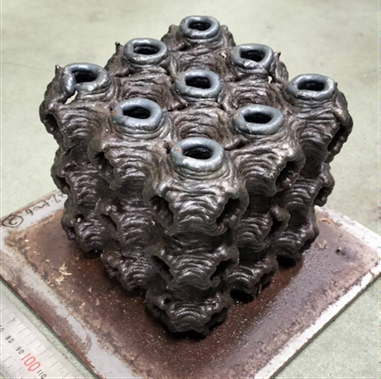
Schwrz primitive TPMS structure fabricated by DED-Arc
1. Introduction
Lightweight lattice structures with high mechanical strength have been investigated extensively in engineering. Triply periodic minimal surfaces (TPMSs), as shown in Fig. 1, are a representative example of such structures.
TPMSs are a type of porous structure composed of minimal surfaces repeated periodically in three orthogonal directions in three-dimensional space. Compared with conventional lattice structures, TPMSs can effectively suppress stress concentrations and offer the potential for further weight reduction and superior energy-absorption performance. Hence, researchers have extensively investigated the application of TPMSs in materials designed to absorb impacts 1,2,3.
Additionally, TPMSs exhibit a large specific surface area and excellent biocompatibility, thereby motivating researchers to investigate their potential application in heat exchangers 4,5, medical devices 6,7, secondary batteries 8, catalyst supports 9, and electromagnetic wave absorbers 10.
Generally, TPMSs cannot be fabricated using conventional subtractive manufacturing processes such as machining or milling owing to their complex curved geometries and unique internal structure. However, the widespread adoption of additive manufacturing technologies has enabled the fabrication of complex geometries using computer-aided design (CAD).
Representative examples include the fabrication of TPMSs using ultraviolet-curable resins via stereolithography 11,12, as well as metal-based fabrication using powder bed fusion with metal powders. Furthermore, TPMS designs incorporating gradients in cell size or sheet thickness have been proposed 13, and increases in the design freedom have been attempted by controlling the level parameter \(C\) in the mathematical equations defining the geometry of TPMS structures 14. Additionally, detailed investigations into functional properties such as energy absorption have been reported 15. However, to the best of our knowledge, no investigations into the fabrication of TPMS using directed energy deposition (DED) have been reported 16.
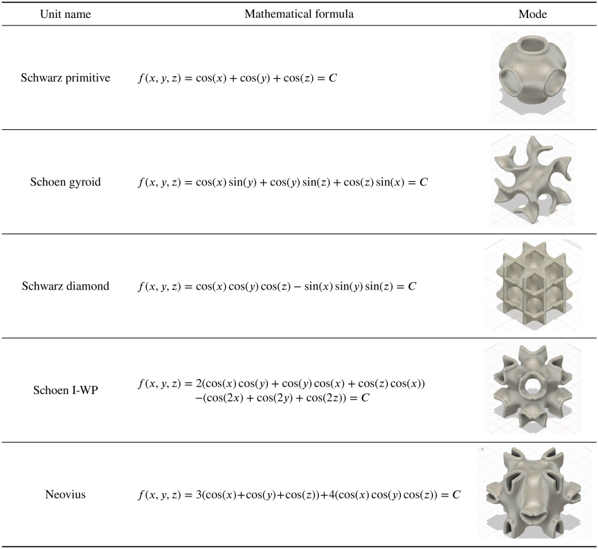
Fig. 1. List of TPMSs.
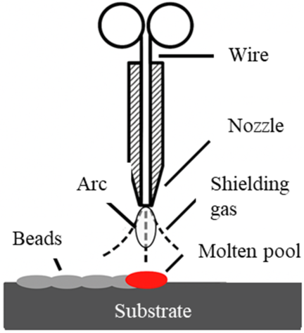
Fig. 2. DED-Arc.
Wire and arc-directed energy deposition (DED-Arc) processes are characterized by the system configuration shown in Fig. 2. They have been shown to provide some notable advantages in fabricating large-scale structures rapidly while minimizing material waste 17. However, DED-Arc presents several drawbacks, including a large heat input, which can induce distortion and deformation, as well as challenges in fabricating precise geometries and complex structures.
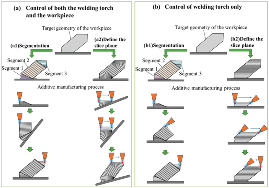
Fig. 3. Classification of fabrication strategies using DED-Arc.
Hence, the application of DED-Arc has primarily focused on the fabrication of simple geometries that require subsequent post-processing 18,19,20. Consequently, studies pertaining to manufacturing strategies for fabricating complex geometries using DED-Arc are limited.
However, the fabrication of TPMSs using DED-Arc would expand the range of applications in mechanical engineering and architectural fields by exploiting the excellent mechanical properties of TPMS shapes.
As shown in Fig. 3, manufacturing strategies for DED-Arc depend on whether the posture of both the welding torch and workpiece can be controlled. In the case of Fig. 3(a), the object is sufficiently small to allow the control of both postures. In the case of Fig. 3(b), only the posture of the welding torch can be controlled owing to the size of the object to be installed. In the former case, fabrication is performed while controlling the relative positions of the welding torch and workpiece to avoid overhangs throughout the manufacturing process. In that regard, strategies such as partitioning the built object into multiple segments (a1) 21 and adjusting the slice plane orientation and pitch (a2) 22,23 have been proposed.
By contrast, when only the welding torch is directly controlled, its orientation is maintained to continuously face the workpiece. In this approach, the vertical layer height varies depending on the overhang angle present in the object being fabricated. Hence, a method has been proposed where the object is partitioned into multiple segments to maintain the orientation of the welding torch and the height of each layer (b1) 24. Additionally, a strategy that controls the feeding speed of the torch to maintain a uniform layer height has also been reported (b2) 25.
In this study, we adopt a manufacturing strategy based on a fixed substrate to fabricate a TPMS without size or weight constraints.
When fabrication is performed with the substrate fixed horizontally, two characteristic geometric features appear in TPMS structures composed of curved surfaces, as illustrated in Fig. 4. One of these features is an inclined thin-wall structure that corresponds to a conventional overhang, which has been investigated in previous studies pertaining to DED-Arc-based fabrication 26. Another feature is the overhang in the surface extension direction, in which the width of the curved surface increases with height. To our knowledge, no manufacturing strategies for DED-Arc designed specifically to address this type of overhang have been reported.
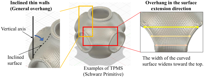
Fig. 4. Two characteristic geometric features of TPMS.
When conventional thin-wall fabrication methods are directly applied to the fabrication of overhangs in the surface extension direction, a problem arises in which insufficient deposition height occurs at both ends of the thin wall. As shown in Fig. 5, although an ideal process requires horizontal deposition, insufficient deposition height at the ends is unavoidable in practice. Resolving this issue is essential to stably and reliably fabricate TPMSs using DED-Arc.
Hence, we propose a manufacturing strategy for fabricating overhangs in the surface extension direction based on DED-Arc. Furthermore, we demonstrate the feasibility of TPMS fabrication using DED-Arc by applying the proposed strategy.
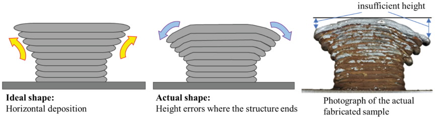
Fig. 5. Ideal fabrication of overhang in surface extension direction and resulting insufficient layer height.
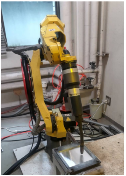
Fig. 6. ARC Mate 100iC equipped with welding torch at its end effector.
2. Fabrication of Overhang in Surface Extension Direction
2.1. Experimental Method
In this study, an ARC Mate 100iC robotic system (FANUC Corp.) was used to control the fabrication process, as shown in Fig. 6. Fabrication was performed via cold metal transfer (CMT), which enabled a low heat input through controlled power modulation, using a TransPuls Synergic 5000 CMT MV welding power source (Fronius International GmbH). A mild steel wire with a diameter of 1.2 mm was used, and the process parameters are shown in Table 1.
| Parameters | Units | Value |
| Welding current | A | 100 |
| Welding voltage | V | 10.8 |
| Torch feed speed | mm/min | 300 |
| Wire feed speed | m/min | 2.2 |
| Wire material | – | YGW16 |
| Wire diameter | mm | 1.2 |
| Shielding gas (Ar) | – | 100% |
| Shielding gas flow rate | L/min | 15 |
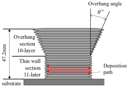
Fig. 7. Sample geometry.
We fabricated samples with the geometry shown in Fig. 7 to investigate the effects of the overhang angle and spot deposition on the improvement of the deposition height at the edges. The overhang angle in the surface extension direction was defined as the angle \(\theta\) formed between the vertical direction and sample contour. During the deposition, the feeding speed of the torch for the first layer was set to 20 mm/min to ensure sufficient heat input and adequate bonding to the substrate. From the second layer onward, the torch feed speed was increased to 30 mm/min, and the overhang region was initiated from the 12th layer. In the overhang region, the deposition length was incrementally extended at both ends of each layer, which created an inverted trapezoidal geometry with a horizontal top surface. The deposition direction was alternated for each layer and a bidirectional (back-and-forth) deposition strategy was adopted.
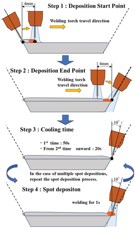
Fig. 8. Deposition process of overhang in surface extension direction.
2.2. Manufacturing Strategy for Overhang in Surface Extension Direction
In fabricating overhanging shapes, spot deposition was applied to compensate for the insufficient amount of metal deposited at the endpoints of each deposition path. An overview of the proposed deposition process is presented in Fig. 8.
Steps 1 and 2 in Fig. 8 correspond to a conventional deposition process using DED-Arc. In this study, we introduce a specific control strategy in which the welding torch is inclined toward the fabricated component at both the starting and ending points of each deposition path. The inclination angle of the torch is set equal to the overhang angle in the surface extension direction. This control prevents the non-initiation of welding due to the absence of contact between the wire and workpiece and the resulting inadequate short-circuiting. Because the edges of components fabricated via DED-Arc are typically rounded, the resulting width is slightly smaller than the width of the target geometry. Consequently, the wire fails to establish contact with the workpiece if the welding torch is maintained in a vertical orientation throughout the process.
The torch control sequence is as follows. At the beginning of the deposition, the welding torch is inclined toward the deposition starting point at an angle equal to the overhang angle. Subsequently, welding is initiated. While the torch travels 4 mm from the starting point, the inclination angle is gradually changed to a vertical orientation (Step 1). From a position 4 mm before the deposition endpoint, the torch is re-inclined, and at the endpoint, it reaches an angle equal to that of the overhang, after which the deposition process is terminated (Step 2).
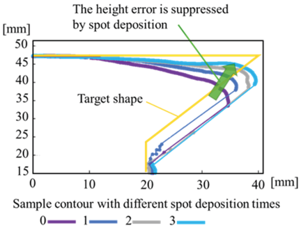
Fig. 9. Sample geometry with spot depositions that improved the insufficient layer height.
Steps 3 and 4 in Fig. 8 illustrate the spot deposition process. First, a cooling period of 50 s is introduced (Step 3), followed by deposition for 1 s (Step 4). The inclination angle of the welding torch during spot deposition is set to 10° based on the results of preliminary experiments. When multiple spot depositions are applied, Steps 3 and 4 are repeated; for the second and subsequent cycles, the cooling time is reduced to 20 s. The first spot deposition is preceded by a continuous path, thus resulting in more heat accumulating in the fabricated object compared with the case of spot deposition for 1 s. Therefore, the cooling time before spot deposition is set shorter than that of the first spot deposition. Spot deposition is not applied at the starting point of the deposition because sufficient metal is inherently deposited therein owing to the characteristics of DED-Arc.
The improvement to the insufficient deposition height at the thin-walled edges achieved by applying spot deposition is shown in Fig. 9.
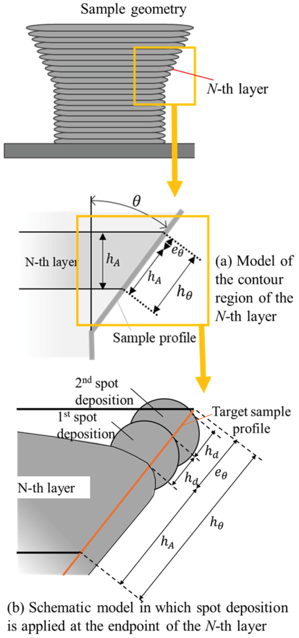
Fig. 10. Model diagram showing various parameters.
2.3. Geometric Model of Insufficient Layer Height in Overhang in Surface Extension Direction
The insufficient height deposited at both edges during the fabrication of the overhang in the surface extension direction can be explained from a geometric perspective. Fig. 10(a) schematically illustrates a model of the contour region of the \(N\)-th layer in a thin wall with an overhang in the surface extension direction. Let the contour length of the \(N\)-th layer be denoted as \(h_{\theta}\) and the average height of each layer be denoted as \(h_A\). Notably, \(h_{\theta}\) and \(h_A\) do not have the same value. The difference between \(h_{\theta}\) and \(h_A\), denoted by \(e_{\theta}\), can be expressed by the following geometric relationship:
To compensate for this shortage of deposited metals, spot deposition was applied at the endpoint of each layer. The value of \(e_{\theta}\) increases with the overhang angle \(\theta\) in the surface extension direction. Therefore, the amount of deposited metal must be adjusted based on \(\theta\). In this study, the deposited metal was controlled by varying the number of spot depositions. Fig. 10(b) illustrates the manner by which spot deposition was applied at the endpoint of the \(N\)-th layer. Here, \(h_d\) denotes the increase in the contour-wise layer height achieved by a single spot deposition and \(n\) denotes the number of spot depositions applied. The shortage of deposited metals \(e_{\theta}\) can be sufficiently compensated when the following relationship is satisfied:
By substituting Eq. (1) into Eq. (2) and rearranging the expression with respect to \(n\), the following relationship between the number of spot depositions \(n\) and the overhang angle \(\theta\) in the surface extension direction is obtained:
These relationships allow one to theoretically estimate the \(n\) required to compensate for the insufficient deposition height as a function of \(\theta\) in the surface extension direction. However, the parameters \(h_A\) and \(h_d\) in Eq. (3) are constants that are governed by the process parameters. Therefore, their values must be determined in advance through preliminary experiments.
2.4. Sample-Fabrication Experiments
To derive the constants \(h_A\) and \(h_d\), multiple samples were fabricated with overhang angles of \(\theta=30°\) and \(\theta=40°\) in the surface extension direction. Additionally, \(n\) was varied depending on the angle. Specifically, three types of samples were prepared for \(\theta=30°\) with zero to two spot depositions, and four types were prepared for \(\theta=40°\) with zero to three spot depositions.
Figure 11 shows a comparison of the contour-wise layer height per layer with \(h_{\theta}\) for these samples. Additionally, the figure shows the value of \(h_d\), which represents the increase in layer height achieved via single-spot deposition, as determined from comparisons among the samples. Based on the average of these results, \(h_d=0.28\) was obtained under the process parameters used in this study. Additionally, the average layer height per layer was evaluated as \(h_A=2.16\) based on the measured layer heights of the samples.
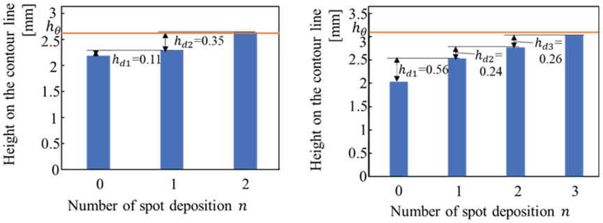
Fig. 11. Variation in deposition height per layer on contour with increasing number of spot depositions (left: 30° overhang angle, right: 40° overhang angle).
Using these experimentally derived constants, the relationship between \(n\) and \(\theta\) in the surface extension direction under the present process parameters can be expressed as follows:
Figure 12 presents a graphical representation of Eq. (4), where the horizontal and vertical axes represent \(\theta\) and \(n\), respectively. The blue curve represents the value calculated using Eq. (4). The orange curve represents the corresponding \(n\) determined by rounding the calculated values to the nearest integer. Because the metal deposited at the layer endpoints tends to be insufficient, we rounded the calculated values to determine the required \(n\).
For \(\theta=30°\), \(n\) was calculated to be approximately 1.30; therefore, two spot depositions were applied. For \(\theta=40°\), \(n\) was calculated to be approximately 2.58, which resulted in three spot depositions. Under both conditions, the contour-wise layer height reached \(h_{\theta}\), as shown in Fig. 11. Furthermore, the fabricated-sample geometries shown in Fig. 13 show that the top surfaces of the samples were flat at both angles, which indicates that an ideal horizontal deposition was achieved.
Based on these results, we conclude that the relationship between \(\theta\) in the surface extension direction and \(n\) can be well described by Eq. (4) under the deposition conditions used in this study.
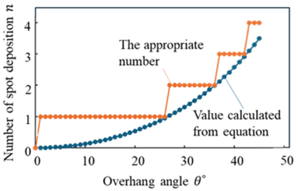
Fig. 12. Relationship between overhang angle and appropriate number of spot deposition.
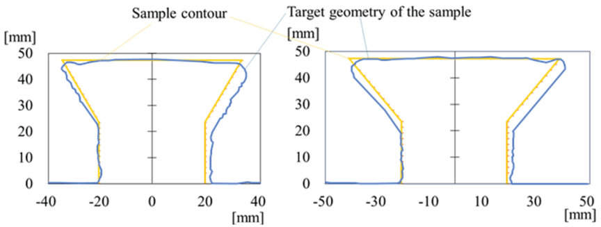
Fig. 13. Appearance of samples fabricated horizontally (left: 30° overhang angle with two spot depositions, right: 40° overhang angle with three spot depositions).
3. Fabrication of TPMS
3.1. Manufacturing Strategy for TPMS Fabrication
3.1.1. Basic Manufacturing Strategy
TPMS structures were fabricated based on the proposed manufacturing strategy for overhangs described in the previous section. The fabrication system was controlled using an original CAM system developed using the Python programming language with Visual Studio 2022. The CAM system was configured to slice the target geometry with planes parallel to the substrate and generate deposition paths from each cross-sectional contour. During fabrication along the generated paths, the welding torch was tilted to follow the curved surface of the fabricated geometry. The maximum torch inclination angle was limited to 35° to prevent interference between the torch and deposited structure.
As shown in Fig. 14, the manufacturing strategy for TPMS fabrication primarily comprises three components.
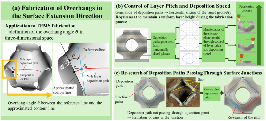
Fig. 14. Three manufacturing strategies for TPMS fabrication.
The first strategy involves the fabrication of overhangs in the surface extension direction. Here, \(\theta\) is calculated in three-dimensional space and \(n\) is determined using Eq. (4).
The second strategy is to control the pitch of each layer and the feeding speed of the torch. Because the deposition paths are generated from horizontal slicing planes, horizontal surfaces corresponding to these slicing planes must be maintained throughout the fabrication process 25. Therefore, the layer pitch and torch feed speed were controlled to ensure a uniform height for each deposited layer.
The third strategy is to identify deposition paths that pass through surface junctions again. If a deposition path does not pass through a certain junction point, then bonding between adjacent curved surfaces does not occur during fabrication, thus resulting in defects. Hence, when a junction point exists between consecutive slicing planes, the deposition path on the corresponding slicing plane is replaced by a path that passes through the junction point. This approach effectively suppresses defects at surface junctions.
3.1.2. Calculating \(\theta\) in Three-Dimensional Space
An appropriate \(n\) at the endpoint of each deposition path must be determined to fabricate overhangs in the direction in which the surface is extended in three-dimensional space. Hence, the \(\theta\) at the corresponding endpoint must be calculated. The experimental samples presented in the previous section featured two-dimensional geometries for which \(\theta\) can be readily defined via a comparison with the vertical axis. However, in three-dimensional space, the vertical axis does not necessarily lie on the curved surface, in which case the angle calculated based on this axis becomes inaccurate. Therefore, as illustrated in Fig. 15, we introduce a reference line that defines the “upward direction” in the vicinity of the deposition endpoint on the curved surface, for which \(\theta\) can be calculated via a comparison with this reference line.
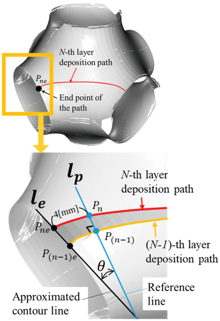
Fig. 15. Overhang angle in surface extension direction \(\theta\) at point \(P_{\textit{ne}}\) in three-dimensional space.
In Fig. 15, the deposition endpoint is denoted as \(P_{\mathit{ne}}\). The contour near the deposition endpoint is approximated by a straight line connecting \(P_{\mathit{ne}}\) and the contour point \(P_{(n-1)e}\) on the slicing plane immediately below. Additionally, a point \(P_{n}\) is defined on the deposition path at a distance of 4 mm from \(P_{\mathit{ne}}\), and the reference line is defined as the line connecting \(P_n\) to the nearest point \(P_{(n-1)}\) on the slicing plane immediately below. A distance of 4 mm between \(P_{\mathit{ne}}\) and \(P_n\) was selected because the CAM system used in this study generates points along the deposition path at 4 mm intervals.
Let the vector representing the approximate contour line be the contour vector \(\boldsymbol{l}_{\boldsymbol{e}}\), and the vector representing the reference line be the reference vector \(\boldsymbol{l}_{\boldsymbol{p}}\). Using the inner product of these two vectors, one can calculate \(\theta\) as follows:
3.1.3. Control of Layer Pitch and Torch Feed Speed
The inclination of a curved surface varies depending on location, and this variation can occur even along a single deposition path, as shown in Fig. 16(a). In general, a larger surface inclination angle results in a smaller layer height in the vertical direction.
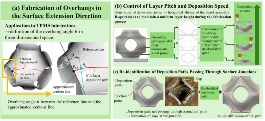
Fig. 16. Control of layer pitch and torch feed speed.
In this study, the smallest layer height observed on each slicing plane corresponding to the region with the largest surface inclination was selected as the reference value and defined as the layer pitch, i.e., the spacing between slicing planes.
However, when the torch feed speed was maintained at a constant value, excessive metal deposition occurred in the regions with small surface inclinations, as shown in Fig. 16(b). Hence, the feeding speed of the torch was increased in small inclined regions to reduce the local layer height to achieve fabrication with a uniform height consistent with the prescribed layer pitch.
However, adjusting the layer height based on the torch feed rate becomes more difficult with larger surface inclination angles and smaller layer pitch values. Therefore, the minimum-value range of the layer pitch was limited to a region in which the surface inclination angle was 45° or less. When performing deposition at an inclination angle of 45° or more, the layer should be separated into two or more layers, as shown in Fig. 17. The deposition path outside the slice plane is referred to as an intermediate layer. Notably, near-horizontal surfaces can be created by inserting an additional intermediate layer.
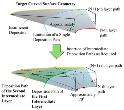
Fig. 17. Insertion of intermediate layers for surface inclination angles of 45° or greater.
3.1.4. Re-Identification of Deposition Paths Passing Through Junction Points
During the generation of deposition paths by slicing the target geometry, the slicing plane rarely coincides with the junction point between curved surfaces, as shown in Fig. 18(a). In such cases, the deposition path does not pass through the junction point, which results in defects characterized by gaps at the junction. Hence, we introduce a re-identified deposition path. In this approach, the deposition path on the slicing plane following the junction point is replaced with a path that passes through the junction, as shown in Fig. 18(b). This approach enables gap-free fabrication at surface junctions.
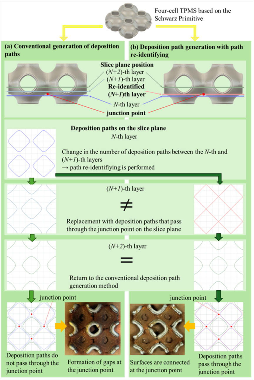
Fig. 18. Process of generating deposition paths at surface-junction region.
3.2. Single-Cell Fabrication Experiments
Based on the manufacturing strategy described above, we conducted single-cell fabrication experiments for Schwarz primitive and Schoen gyroid structures. Each cell was defined as a cube with sides measuring 60 mm. The fabrication equipment and deposition conditions were identical to those used in the sample fabrication experiments described in the previous section. Successfully fabricated samples are shown in Fig. 19.
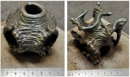
Fig. 19. Single cell sample of Schwarz primitive and Schoen gyroid.
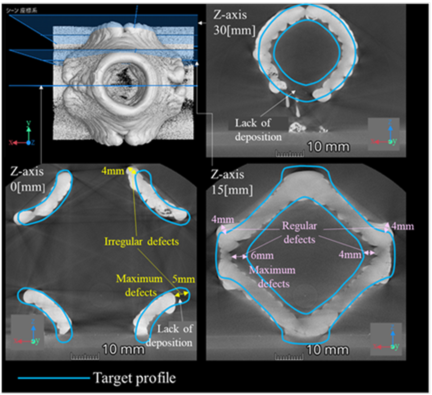
Fig. 20. Comparison between fabricated cross-sections and the target profile at \(Z=0\), 15, and 30 mm.
For the single-cell Schwarz primitive sample, we acquired three-dimensional data using an X-ray computed tomography (CT) scanner (TXS-33000FD, Toshiba IT Control Systems) and compared them with the target geometry. The results are presented in Fig. 20. The fabricated geometry generally reflected the target shape across all cross sections. Since the shape data obtained from the X-ray CT scans were complicated, we could not convert them into STL data and compare the shape with CAD data. Therefore, we evaluated the geometric accuracy by measuring the defect of cross-sectional profiles from the target geometry. We classified the observed shape defects into irregular and regular defects. The irregular defects indicated by the yellow lines in Fig. 20 reached a maximum of approximately 5 mm. These defects were speculated to be caused by molten metal collapsing during deposition in large overhang regions on curved surfaces, thus resulting in the insufficient deposition of molten metal. By contrast, the regular defects—indicated by pink lines—reached a maximum of approximately 6 mm. These defects were speculated to have originated from the deposition path. Therefore, the toolpath strategy should be further optimized to mitigate these deviations.
Additionally, the irregular defects can be caused by the bending of the wire supplied from the tip of the welding torch. In regions where the wire bends away from the deposited structure, contact between the wire and structure becomes less likely. Wire bending can disrupt the contact between the wire and deposited material. This tendency becomes particularly significant at large inclination angles. Therefore, future studies should focus on developing methods to control the posture of welding torch devices that explicitly consider this wire-bending behavior.
Additionally, surface defects such as blowholes and notch-like flaws were observed in the fabricated specimens, as shown in Fig. 21. The former occurred frequently because of heat accumulation within the deposited structure, whereas the latter originated from accidental bead interruptions that expanded as the deposition process progressed. The defects shown in Fig. 21 are expected to be the direct cause of the decrease in strength. Furthermore, the number of heat input cycles is speculated to vary depending on the location due to spot deposition, thus resulting in localized inconsistencies in the metal structure and strength. These effects must be investigated further. Hence, future studies should focus on developing a system that can monitor the temperature of a specified component and the condition of beads in real time to enable adaptive cooling and bead compensation during fabrication. Furthermore, because the optimal conditions for dwell time have not yet been investigated, further studies are necessitated to achieve higher precision levels and shorter processing times.
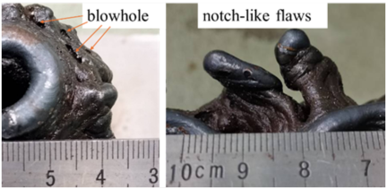
Fig. 21. Surface defects found on the surface of the sample. The image at left shows a metal blowhole, and that at right shows notch-like flaws.
3.3. Fabrication of Multicell TPMS Structures
Finally, multicell TPMS structures of the Schwarz primitive and Schoen gyroid were fabricated. The structures comprised 27 cells arranged in a \({3\times 3\times 3}\) configuration, with each cell defined as a cube with sides measuring 40 mm. Successfully fabricated samples are shown in Fig. 22.
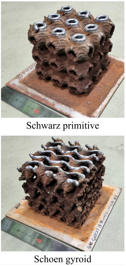
Fig. 22. Schwarz primitive and Schoen gyroid TPMS printed with DED-Arc.
A method similar to the spot deposition proposed in this study, which involves repeated welding at a single point in DED-Arc, has been used in studies pertaining to the fabrication of columnar structures. These studies used metals other than soft iron, such as stainless steel 27. This indicates that the proposed method may be applicable to a wider range of materials.
The proposed method, which includes spot deposition, increases the fabrication time. However, fabricating a TPMS structure without spot deposition is challenging; thus, a decrease in fabrication efficiency is inevitable. Meanwhile, the fabrication time can be reduced by optimizing the path planning, such as by performing spot deposition on other areas during the dwell time. In future studies, the dwell time and the process conditions for spot deposition should be optimized.
4. Conclusions
In this study, we proposed a manufacturing strategy for overhangs in the surface extension direction as an essential aspect of TPMS fabrication using wire and DED-Arc. The results of an experimental evaluation validated the effectiveness of the proposed approach. Our conclusions are summarized as follows:
-
・
The insufficient layer height at both ends of the deposition paths is a critical issue that can be effectively mitigated by applying multiple spot depositions at the endpoint of each layer.
-
・
The required number of spot depositions depends on the overhang angle, and the appropriate number can be quantitatively determined using Eq. (4).
-
・
Based on these findings, we successfully fabricated representative TPMS structures with three-dimensional curved surfaces, namely Schwarz primitive and Schoen gyroid shapes. Furthermore, TPMS structures composed of 27 interconnected cells arranged in a \(3\times 3\times 3\) configuration were successfully fabricated. These results indicate that TPMS fabrication is feasible using DED-Arc.
-
・
Although the fabrication of TPMS structures was successfully demonstrated, several defects were observed. Accordingly, future studies should focus on developing an improved manufacturing strategy that accounts for the wire-bending behavior. Furthermore, a system should be developed to monitor the temperature and bead conditions of components in real time to enable adaptive cooling and bead correction during fabrication.
- [1] H. Yin, X. Zheng, G. Wen, C. Zhang, and Z. Wu, “Design optimization of a novel bio-inspired 3D porous structure for crashworthiness,” Compos. Struct., Vol.255, Article No.112897, 2021. https://doi.org/10.1016/j.compstruct.2020.112897
- [2] M. Zhao, D. Z. Zhang, F. Liu, Z. Li, Z. Ma, and Z. Ren, “Mechanical and energy absorption characteristics of additively manufactured functionally graded sheet lattice structures with minimal surfaces,” Int. J. Mech. Sci., Vol.167, Article No.105262, 2020. https://doi.org/10.1016/j.ijmecsci.2019.105262
- [3] A. R. de Oliveira, A. A. Mendes Filho, M. Masoumi, and E. G. del Conte, “Compression and energy absorption of maraging steel primitive scaffolds produced by powder bed fusion,” Int. J. Adv. Manuf. Technol., Vol.116, pp. 1271-1283, 2021. https://doi.org/10.1007/s00170-021-07514-4
- [4] K. Dutkowski, M. Kruzel, and K. Rokosz, “Review of the state-of-the-art uses of minimal surfaces in heat transfer,” Energies, Vol.15, Issue 21, Article No.7994, 2022. https://doi.org/10.3390/en15217994
- [5] R. Attarzadeh, M. Rovira, and C. Duwig, “Design analysis of the ‘Schwartz D’ based heat exchanger: A numerical study,” Int. J. Heat Mass Transf., Vol.177, Article No.121415, 2021. https://doi.org/10.1016/j.ijheatmasstransfer.2021.121415
- [6] Z. Dong and X. Zhao, “Application of TPMS structure in bone regeneration,” Eng. Regen., Vol.2, pp. 154-162, 2021. https://doi.org/10.1016/j.engreg.2021.09.004
- [7] A. Tikhonov, P. Evdokimov, E. Klimashina, S. Tikhonova, E. Karpushkin, I. Scherbackov, V. Dubrov, and V. Putlayev, “Stereolithographic fabrication of three-dimensional permeable scaffolds from CaP/PEGDA hydrogel biocomposites for use as bone grafts,” J. Mech. Behav. Biomed. Mater., Vol.110, Article No.103922, 2020. https://doi.org/10.1016/j.jmbbm.2020.103922
- [8] J. G. Werner, G. G. Rodríguez-Calero, H. D. Abruña, and U. Wiesner, “Block copolymer derived 3D interpenetrating multifunctional gyroidal nanohybrids for electrical energy storage,” Energy Environ. Sci., Vol.11, pp. 1261-1270, 2018. https://doi.org/10.1039/c7ee03571c
- [9] H.-Y. Lei, J.-R. Li, Q.-H. Wang, Z.-J. Xu, W. Zhou, C.-L. Yu, and T.-Q. Zheng, “Feasibility of preparing additive manufactured porous stainless steel felts with mathematical micro pore structure as novel catalyst support for hydrogen production via methanol steam reforming,” Int. J. Hydrog. Energy, Vol.44, Issue 45, pp. 24782-24791, 2019. https://doi.org/10.1016/j.ijhydene.2019.07.187
- [10] Y. Feng, X. Guo, K. Huang, H. Elsayed, G. Franchin, H. Gong, and P. Colombo, “Enhanced electromagnetic microwave absorption of SiOC ceramics targeting the integration of structure and function,” J. Eur. Ceram. Soc., Vol.41, Issue 13, pp. 6393-6405, 2021. https://doi.org/10.1016/j.jeurceramsoc.2021.06.007
- [11] W. D. Abueidda, M. Elhebeary, C. S. Shiang, S. Pang, R. K. Abu Al-Rub, and I. M. Jasiuk, “Mechanical properties of 3D printed polymeric gyroid cellular structures: Experimental and finite element study,” Mater. Des., Vol.165, Article No.107597, 2019. https://doi.org/10.1016/j.matdes.2019.107597
- [12] S. Yu, J. Sun, and J. Bai, “Investigation of functionally graded TPMS structures fabricated by additive manufacturing,” Mater. Des., Vol.182, Article No.108021, 2019. https://doi.org/10.1016/j.matdes.2019.108021
- [13] N. Qiu, J. Zhang, F. Yuan, Z. Jin, Y. Zhang, and J. Fang, “Mechanical performance of triply periodic minimal surface structures with a novel hybrid gradient fabricated by selective laser melting,” Eng. Struct., Vol.263, Article No.114377, 2022. https://doi.org/10.1016/j.engstruct.2022.114377
- [14] X. Zhang, X. Xie, Y. Li, B. Li, S. Yan, and P. Wen, “Mechanical behavior of Al-Si10-Mg P-TPMS structure fabricated by selective laser melting and a unified mathematical model with geometrical parameter,” Materials, Vol.16, No.2, Article No.468, 2023. https://doi.org/10.3390/ma16020468
- [15] N. Qiu, Y. Wan, Y. Shen, and J. Fang, “Experimental and numerical studies on mechanical properties of TPMS structures,” Int. J. Mech. Sci., Vol.261, Article No.108657, 2024. https://doi.org/10.1016/j.ijmecsci.2023.108657
- [16] J. Feng, J. Fu, X. Yao, and Y. He, “Triply periodic minimal surface (TPMS) porous structures: From multi-scale design, precise additive manufacturing to multidisciplinary applications,” Int. J. Extreme Manuf., Vol.4, No.2, Article No.022001, 2022. https://doi.org/10.1088/2631-7990/ac5be6
- [17] D. G. Ahn, “Directed energy deposition (DED) process: State of the art,” Int. J. Precis. Eng. Manuf.-Green Technol., Vol.8, No.2, pp. 703-742, 2021. https://doi.org/10.1007/s40684-020-00302-7
- [18] A. Nishiyama, S. Kayashima, N. Sumi, T. Hashimoto, T. Abe, and J. Kaneko, “Process planning with removal of melting penetration and temper colors in 5-axis hybrid additive and subtractive manufacturing,” Int. J. Automation Technol., Vol.17, No.4, pp. 356-368, 2023. https://doi.org/10.20965/ijat.2023.p0356
- [19] T. Cordkaew, J. Kaneko, and T. Abe, “Analysis of the relationship between process parameters and microhardness for the finishing process by wire arc additive manufacturing combined with the FSB tool of austenitic stainless steel 316L,” Int. J. Automation Technol., Vol.18, No.5, pp. 688-701, 2024. https://doi.org/10.20965/ijat.2024.p0688
- [20] T. Abe and H. Sasahara, “Residual stress and deformation after finishing of a shell structure fabricated by direct metal lamination using arc discharge,” Int. J. Automation Technol., Vol.6, No.5, pp. 611-617, 2012. https://doi.org/10.20965/ijat.2012.p0611
- [21] J. Ye, P. Kyvelou, F. Gilardi, H. Lu, M. Gilbert, and L. Gardner, “An end-to-end framework for the additive manufacture of optimized tubular structures,” IEEE Access, Vol.9, pp. 165476-165489, 2021. https://doi.org/10.1109/access.2021.3132797
- [22] J. Marcotte, S. Mishra, and J. T. Wen, “Robotic wire arc additive manufacturing with variable height layers,” arXiv:2412.04536, 2024. https://doi.org/10.48550/arXiv.2412.04536
- [23] T. Kamioka, S. Ishikawa, and H. Sasahara, “Fabrication of elbow pipe by direct metal lamination using arc discharge while maintaining the molten pool in a horizontal position,” Int. J. Automation Technol., Vol.4, No.5, pp. 422-431, 2010. https://doi.org/10.20965/ijat.2010.p0422
- [24] T. Feucht, B. Waldschmitt, J. Lange, and M. Erven, “Additive manufacturing of a bridge in situ,” Steel Constr., Vol.15, Issue 2, pp. 100-110, 2022. https://doi.org/10.1002/stco.202100045
- [25] T. Abe and H. Sasahara, “Development of the shell structures fabrication CAM system for direct metal lamination using arc discharge: Lamination height error compensation by torch feed speed control,” Int. J. Precis. Eng. Manuf., Vol.16, pp. 171-176, 2015. https://doi.org/10.1007/s12541-015-0022-4
- [26] P. Kazanas, P. Deherkar, P. Almeida, H. Lockett, and S. Williams, “Fabrication of geometrical features using wire and arc additive manufacture,” Proc. Inst. Mech. Eng., Part B: J. Eng. Manuf., Vol.226, No.6, pp. 1042-1051, 2012. https://doi.org/10.1177/0954405412437126
- [27] V. Laghi, M. Palermo, L. Tonelli, G. Gasparini, V. Girelli, L. Ceschini, and T. Trombetti, “Mechanical response of dot-by-dot wire-and-arc additively manufactured 304L stainless steel bars under tensile loading,” Constr. Build. Mater., Vol.318, Article No.125925, 2022. https://doi.org/10.1016/j.conbuildmat.2021.125925
This article is published under a Creative Commons Attribution-NoDerivatives 4.0 Internationa License.