Research Paper:
Dense 3D Mapping in Extremely Dark Environments Based on Colored LLAH Descriptor Using Phosphorescent Materials
Shunsei Takarabe and Yonghoon Ji†

Graduate School of Advanced Science and Technology, Japan Advanced Institute of Science and Technology
1-1 Asahidai, Nomi, Ishikawa 923-1292, Japan
†Corresponding author

In this paper, we propose a dense three-dimensional (3D) mapping approach for extremely dark environments based on structure from motion (SfM) and multi-view stereo (MVS) using a general optical camera and phosphorescent materials in extremely dark environments. Conventional methods that use phosphorescent emission as a visual feature suffer from unstable feature correspondence when gradient-based descriptors are used, owing to the temporal decay of the emission intensity. Maintaining uniform brightness requires repeated ultraviolet irradiation, which is impractical in power-limited environments such as lunar caves. To address this issue, we apply locally likely arrangement hashing as a novel framework to find the corresponding feature points for SfM by leveraging the geometric arrangement and luminous color of phosphorescent materials. The experimental results demonstrated that the proposed SfM–MVS framework can construct a geometrically accurate dense 3D map even in extremely dark environments.
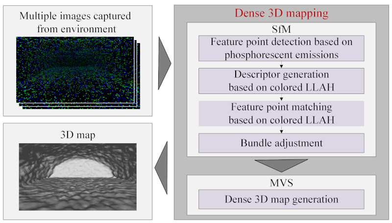
Overview of the proposed framework for dense 3D mapping in extremely dark environments
1. Introduction
Recently, the exploration of lunar and planetary environments using autonomous mobile robots has gained attention in terms of future resource exploration and planetary base construction. For efficient exploration by autonomous mobile robots, highly accurate self-localization and safe navigation need to be ensured 1. This requires the construction of highly accurate three-dimensional (3D) maps. 3D LiDAR sensors, which can acquire 3D point cloud data, are widely used to build highly accurate 3D maps. However, this method is power-consuming, making it unsuitable for lunar or planetary environments where power constraints are severe. Therefore, dense 3D reconstruction using optical cameras with low power consumption is a promising option 2. Representative examples of building dense 3D maps using image data include structure from motion (SfM) and multi-view stereo (MVS). SfM estimates the extrinsic camera parameters and a sparse 3D point cloud based on the correspondence between feature points in multiple images. MVS reconstructs a dense 3D model based on the camera poses estimated using SfM. However, these approaches require the acquisition of a sufficient number of feature points to determine the correspondence between multiple images, making them difficult to apply to permanently shadowed areas, such as caves and completely dark environments. As a countermeasure, a camera with headlights mounted on a mobile robot can capture bright images; however, this approach is power-consuming and suffers from image quality degradation owing to shadow generation and overexposure 3,4. Thermography is another method that can be performed in the dark. However, this method has a low resolution; thus, it is unsuitable for high-precision 3D reconstruction 5. To overcome these challenges, our research group proposed an SfM–MVS framework that utilizes phosphorescent materials as visual features for 3D reconstruction 6,7. As shown in Fig. 1, phosphorescent materials that exhibit long-lasting luminescence after ultraviolet irradiation are scattered once on environmental surfaces and observed using an optical camera. With this approach, images can be captured from different viewpoints over a long period without using continuous illumination such as headlights. In addition to lunar and planetary environments, the proposed method is expected to be applicable to extremely dark or texture-poor environments, such as underground caves, tunnel inspections, and indoor exploration during power outages. However, as the brightness of phosphorescent materials decays over time, adopting traditional gradient-based descriptors, such as the scale-invariant feature transform (SIFT) 8 and oriented FAST and rotated BRIEF (ORB) 9, requires ultraviolet illumination to maintain constant brightness during image acquisition. This additional illumination consumes power, rendering it unsuitable for use in power-constrained lunar cave environments. Improving the visibility of the captured images by signal amplification or extending the exposure time may also be considered. However, as the emission intensity decreases over time, the signal-to-noise ratio deteriorates, making it difficult to recover the lost information using only post-processing amplification. Furthermore, extending the exposure time increases the acquisition time and may cause motion blurring during observations with a mobile robot, which can degrade the accuracy of feature extraction. Furthermore, machine-learning-based approaches for feature extraction and matching such as SuperPoint 10, D2-Net 11, SuperGLUE 12, and the local feature transformer 13 have emerged. Although these methods are relatively robust to changes in lighting, applying a machine-learning-based approach to unexplored environments such as the lunar caves investigated in this study is impractical owing to the lack of suitable datasets for pretraining 14.
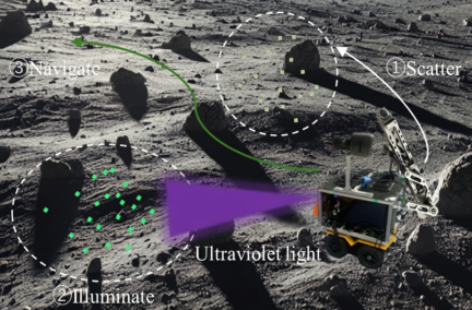
Fig. 1. Conceptual diagram of the autonomous mobile robot exploration of lunar and planetary environments using phosphorescent materials.
To solve the abovementioned issues, a feature representation that does not require brightness gradients or pre-training needs to be used. Therefore, in this study, we focus on the geometric arrangement of phosphorescent materials based on locally likely arrangement hashing (LLAH) 15 to define a brightness-invariant feature descriptor. LLAH describes the local arrangement of features and is widely used for document image retrieval. We propose an approach that applies LLAH to find correspondence between feature points within images, as it can calculate affine invariants from locally arranged point clouds, thereby enabling matching that is robust to changes in appearance 16. However, as the invariants are derived by assuming a local plane, their robustness decreases in uneven 3D environments. Furthermore, LLAH is designed for image retrieval and is not intended to find correspondences between feature points extracted from multiple images, which is a necessary process for SfM.
To address these challenges, this paper proposes a novel feature descriptor, called colored LLAH, based on the emission color and geometric arrangement of phosphorescent materials. In addition, the voting structure based on this descriptor is redefined such that LLAH, which is originally designed for document image retrieval, can be used as a feature correspondence generation method suitable for SfM. The proposed method enables stable feature point matching even in completely dark environments, thereby achieving highly accurate 3D map construction.
The contributions of this study are as follows:
-
We propose a low-power 3D mapping method that does not require additional ultraviolet irradiation when acquiring images, even when the luminescence intensity of phosphorescent materials decays naturally over time.
-
We design a geometric descriptor based on colored LLAH that incorporates the luminescent color of phosphorescent materials as a feature and improves the discrimination performance, which is difficult to achieve using conventional geometric features alone.
-
We redefine LLAH, which is designed for document image retrieval, as a method for finding feature point correspondences for SfM. We also propose a matching scheme that can directly find stable feature point correspondences, even in extremely dark environments.
The remainder of this paper is organized as follows. Section 2 describes the overall configuration of the proposed framework. Section 3 describes feature point detection based on phosphorescent emissions. Section 4 explains the descriptor using colored LLAH, and Section 5 describes the matching scheme between feature points based on colored LLAH. Section 6 presents the experimental results. Finally, Section 7 summarizes the conclusions of this study and discusses future challenges.
Fig. 2. Overview of the proposed dense 3D mapping framework for extremely dark environments.
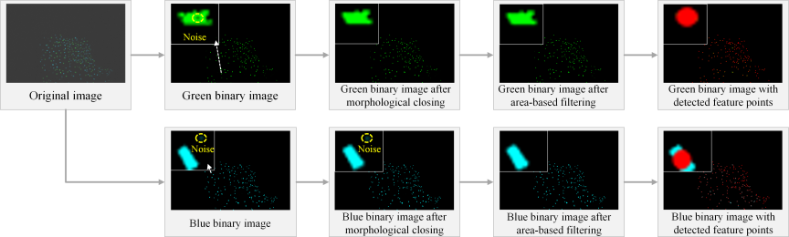
Fig. 3. Procedure for feature point detection corresponding to phosphorescent materials. The original image was brightness-adjusted for better visualization.
2. Overview
Figure 2 shows an overview of the proposed framework. In this study, green and blue phosphorescent materials with long-lasting afterglow are scattered over an environmental surface in advance 17. First, feature points corresponding to the phosphorescent materials are detected from images captured using an optical camera. Subsequently, the original descriptors, called colored LLAH, are generated based on the local geometric structure and color information of each feature point. The correspondence between the images is obtained through feature matching, which maximizes the advantages of LLAH. Random sample consensus (RANSAC) 18 is applied to the obtained corresponding point set to extract inliers with outliers removed. Subsequently, bundle adjustment is performed using the extracted inliers to estimate the camera pose and sparse 3D point cloud. Finally, MVS is performed based on the estimated camera parameters to generate a dense 3D map.
3. Feature Point Detection Based on Phosphorescent Emissions
The procedure for detecting the feature points is shown in Fig. 3. First, the acquired RGB image is converted to the HSV color space to separate the color information from the brightness. This makes the feature extraction less sensitive to changes in illumination. Subsequently, the luminous regions corresponding to the green and blue phosphorescent materials are extracted separately based on the hue and luminance components. Binary images are then generated for each color, and then processing is performed independently to prevent false feature detection caused by color mixing between different phosphorescent emissions. Morphological closure is applied because the extracted luminous regions may have contained small gaps and noise. This operation involves dilation followed by erosion, which fills small holes and gaps within the region and refines the shape of the luminous regions. Connected component analysis is then performed on the luminous regions, followed by area-based filtering to remove minute noise. Finally, the centroid pixel positions of each luminous region are computed and adopted as feature points. The detected feature points, which are indicated by the red dots in Fig. 3, are used for descriptor generation, as described in Section 4, and for feature point matching, as explained in Section 5.
4. Descriptor Generation Based on Colored LLAH
Conventional LLAH selects \(k\) neighboring points around a reference point and generates numerous four-point subsets from the neighboring point set. The affine invariant (i.e., area ratio) of each four-point pair is calculated and quantized to form a hash key, which represents the local point arrangement. However, when the target surface is uneven, the local planarity assumption no longer holds. Moreover, the geometric ratios vary depending on the viewpoint, resulting in an increase in false votes in the hash space. To address this problem, as shown in Fig. 4, this study proposes colored LLAH, which incorporates color information based on phosphorescent emission in addition to conventional geometric quantities. Even when geometric ratios fluctuate owing to surface irregularities, the use of color information enables geometrically similar false correspondence to be separated in the hash space, thereby suppressing false votes.
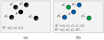
Fig. 4. Comparison of feature representation: (a) conventional LLAH using geometric invariants only and (b) proposed colored LLAH incorporating geometric and color information.
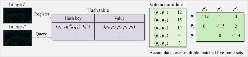
Fig. 5. Feature point matching using five-point voting with colored LLAH.
Let the set of feature points detected in an image be defined as
The geometric ratios \(r_{i,\ell}^{(m)}\) are first mapped into the logarithmic space and then quantized. For each five-point set, the quantized geometric ratios are given by
5. Feature Point Matching Based on Colored LLAH
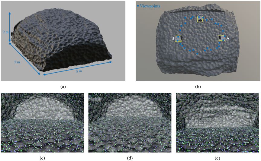
Fig. 6. A 3D cave model manually constructed in a simulation environment: (a) external view of the simulated cave environment, (b) top view of the cave cut away from above, (c) an image captured from viewpoint A, (d) an image captured from viewpoint B, and (e) an image captured from viewpoint C.
The procedure for feature point matching based on colored LLAH is shown in Fig. 5. Let the feature point sets extracted from two images \(I\) and \(I'\) be denoted as
6. Experiments
6.1. Simulation
In simulation experiments, we constructed a virtual cave environment measuring \(5~\mathrm{m} \times 5~\mathrm{m} \times 2~\mathrm{m}\), as shown in Fig. 6(a). The cave model was designed to simulate the irregular terrain observed in real environments such as lunar caves and to evaluate the geometric robustness of the proposed method. Therefore, complex concave and convex structures were intentionally included in the model. The effectiveness of the proposed 3D mapping framework was verified in extremely dark environments. Fig. 6(b) shows the top view of the cave environment cut from above, where the blue dots indicate the camera positions at which the images were captured. A, B, and C represent the viewpoints of the cave interior. The viewpoints were selected from spatially separated positions to illustrate the overall structure of the cave interior. Figs. 6(c)–(e) show the images captured from the corresponding viewpoints shown in Fig. 6(b). Green and blue phosphorescent materials were densely scattered on the environmental surface. A simulated optical camera with an image resolution of \(1280 \times 800\) was mounted on a mobile robot. In the experiments, a total of 30 images were acquired while the robot moved to multiple viewpoints. In the simulation, we focused on evaluating the geometric robustness of the proposed method.
Table 1. Feature matching performance in simulation.

First, we evaluated the effectiveness of the proposed method from the perspective of feature point matching. Two consecutive images in a time series were treated as an image pair, and a comparison was conducted between the two descriptors: LLAH without color information and the proposed colored LLAH. Table 1 shows the average numbers of detected feature points (Feat.), tentative correspondences (Match.), inliers (Inl.), and the inlier ratio (Ratio) for each method. In this evaluation, the inliers were determined using RANSAC-based geometric verification, with the reprojection error threshold set to three pixels. This is a typical setting in SfM pipelines, where the threshold is generally set to a few pixels. Theoretically, at least eight correspondences are required to estimate the fundamental matrix of two images 19. However, noise and outliers are unavoidable in practical SfM pipelines; therefore, several tens of correspondences are often required to achieve robust pose estimation and stable reconstruction 20. In the simulation experiments, the conventional LLAH obtained 541 inliers, whereas the proposed colored LLAH obtained 1,634 inliers. These values significantly exceed the theoretically required number of correspondences, indicating that a sufficient number of correspondences were obtained for performing the SfM reconstruction. Furthermore, the proposed method not only produces a larger number of inliers than the conventional method but also achieves a higher inlier ratio, indicating that the robustness of the feature correspondences is improved. In general, a larger number of correspondences reduce the influence of outliers and improves the accuracy and robustness of the camera pose estimation and 3D reconstruction. Fig. 7 shows a visualization of the feature correspondences obtained by each descriptor, illustrating that the proposed colored LLAH produces a larger number of correct correspondences.
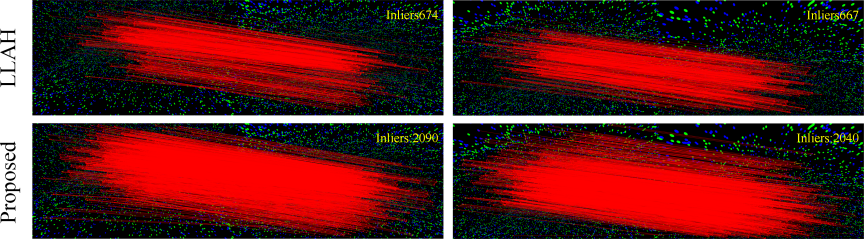
Fig. 7. Comparison of feature point matching in a simulation environment.
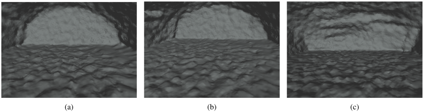
Fig. 8. 3D cave reconstructed using the proposed method in a simulation environment: (a) an image captured from camera viewpoint as viewpoint A shown in Fig. 6(b), (b) an image captured from camera viewpoint as viewpoint B shown in Fig. 6(b), and (c) an image captured from camera viewpoint as viewpoint C shown in Fig. 6(b).
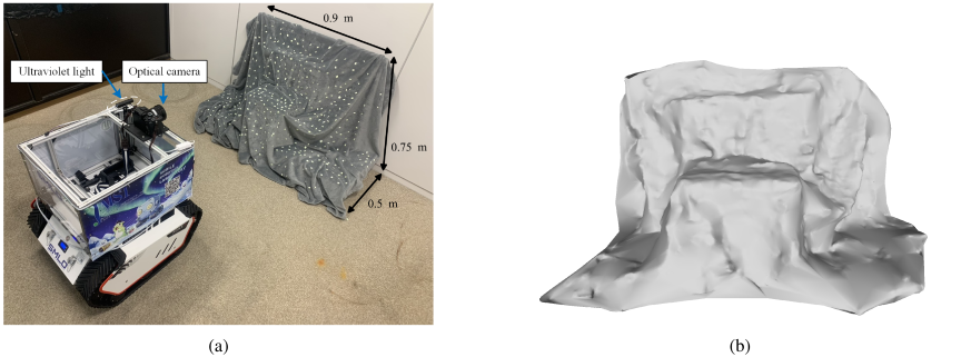
Fig. 9. Results of real-world experiments that were actually conducted in an extremely dark environment: (a) an experimental environment under illuminated conditions and (b) a built 3D map using the proposed framework in real-world conditions.
Subsequently, we performed a comparative evaluation of the 3D map generation using the captured image data in a dark cave in a virtual environment, as shown in Fig. 6. We built dense 3D maps based on COLMAP 21 for SfM and OpenMVS 22 for MVS using each descriptor: LLAH without color information and the proposed colored LLAH. All the generated maps were aligned with the virtual cave model shown in Fig. 6(a). First, manual initial alignment was performed to approximately match the position, orientation, and scale. Subsequently, the alignment was refined using the iterative closest point algorithm 23, in which a similarity transformation, including the scale, was estimated. This algorithm minimizes the distances between points on the reconstructed mesh and the closest points on the ground-truth mesh and is widely used for the registration of meshes and point clouds when no control points or reference points are available 24. This evaluation assesses the effectiveness of the entire 3D reconstruction pipeline, including both SfM and MVS, rather than assessing the performance of SfM in isolation. Since MVS reconstruction is performed based on the camera poses estimated by SfM, the quality of the reconstructed mesh is directly dependent on the accuracy of SfM. Therefore, in this study, the shortest Euclidean distance from each vertex of the reconstructed mesh to the mesh of the virtual cave model regarded as the ground truth is computed, and the root mean square (RMS) of these distances is used as the evaluation metric. The number of vertices in the reconstructed mesh depends on the reconstruction result. We use all vertices to ensure the statistical stability of the evaluation. The increase in the number of vertices itself is not considered as a direct evaluation metric. In this experiment, the reconstruction using LLAH without color information generated 456,498 vertices, whereas the proposed colored LLAH generated 560,244 vertices. The RMS error of the proposed method was 1.3 cm, whereas that of the conventional method was 1.4 cm. Both methods exhibited comparable accuracies in terms of geometric consistency, with the proposed method exhibiting only a slight improvement. In robotic 3D mapping and autonomous navigation, an accuracy of the order of several centimeters is generally considered sufficient for tasks, such as obstacle avoidance and self-localization 25. Figs. 8(a), (b), and (c) are images captured from camera viewpoints A, B, and C shown in Fig. 6(b), respectively, demonstrating that the geometric structure of the manually constructed cave model is accurately reproduced by the proposed method. From these results, although the proposed method achieved a similar level of accuracy to the conventional method in terms of geometric consistency, it demonstrated improved robustness in feature matching by achieving a larger number of inliers and a higher inlier ratio.
6.2. Real Data
Experiments in an actual environment were conducted using a mobile robot, BUNKER MINI manufactured by AgileX Robotics, which is shown in Fig. 9(a). The robot was equipped with an optical camera, a SONY α7S, and an ultraviolet light. The experiment was conducted in a dark room with windows covered with blackout sheets and all lights turned off. The experimental environment was constructed by forming an irregular terrain using fabric materials to simulate the complex cave interior, and its surface was dotted with phosphorescent materials. In the experiments, ultraviolet light was irradiated to make the phosphorescent material glow. Subsequently, the robot was moved to multiple viewpoints, and six images were captured. The camera shutter speed, ISO sensitivity, and aperture value were \(1/3\), 100, and 2.8, respectively.
Table 2. Feature matching performance in a real environment.

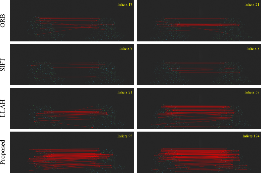
Fig. 10. Comparison of feature point matching in a real environment. The images were brightness-adjusted only for visualization to improve visibility of the matched feature points.
First, we evaluated the effectiveness of the proposed framework from the perspective of feature point matching. As in the simulation experiments, we used image pairs consisting of adjacent frames to compare the correspondence matching results using SIFT, ORB, LLAH without color information, and the proposed colored LLAH. Table 2 lists the average numbers of detected feature points (Feat.), tentative correspondences (Match.), inliers (Inl.), and the inlier ratio (Ratio) for each method. Inliers were determined using RANSAC-based geometric verification, with the reprojection error threshold set to 3 pixels. Table 2 indicates that the proposed colored LLAH descriptor achieved a large number of feature correspondences compared with SIFT, ORB, and the conventional LLAH descriptor by utilizing the color information of the phosphorescent materials. Fig. 10 shows a visualization of the feature correspondences obtained by each descriptor, illustrating that the proposed colored LLAH produces a larger number of correct correspondences. In addition, the processing time of the proposed colored LLAH was evaluated using all image pairs generated from the images acquired in the real-world experiment, and the average processing time was approximately 0.57 s per image pair on a PC equipped with an Intel Core i7-10700 CPU.
Finally, we conducted a comparative evaluation of the 3D map generation using images captured in a real dark situation. Dense 3D maps were built by applying SIFT, ORB, LLAH without color information, and the proposed colored LLAH descriptors. Only the proposed framework using colored LLAH generated a geometrically accurate dense 3D map as shown in Fig. 9(b).
7. Conclusion
In this study, we focused on the challenging task of accurately reproducing geometric structures in dark environments without additional illumination. To address this problem, we proposed a novel feature descriptor, called colored LLAH, based on the emission color and geometric arrangement of phosphorescent materials scattered on environmental surfaces. Furthermore, the voting structure of LLAH was redesigned to reformulate the original document image retrieval framework into a feature correspondence generation method suitable for SfM. Experimental results showed that the proposed framework achieved stable feature point matching even in completely dark environments, thereby enabling the construction of highly accurate 3D maps.
However, this study assumes environments in which phosphorescent materials are manually scattered beforehand, and further investigation is required to apply this framework to autonomous exploration tasks. In the future, we plan to develop low-power actuators and a spraying system that enables robots to autonomously spray phosphorescent materials while moving, thereby extending the proposed method to more realistic scenarios. Furthermore, the proposed method can provide stable visual features even in extremely dark environments with little texture, and therefore has the potential to contribute to the autonomous navigation and path following of mobile robots.
- [1] A. Cauligi, R. M. Swan, M. Ono, S. Daftry, J. Elliott, L. Matthies, and D. Atha, “ShadowNav: Crater-based localization for nighttime and permanently shadowed region lunar navigation,” Proc. of the 2023 IEEE Aerospace Conf., 2023. https://doi.org/10.1109/AERO55745.2023.10115745
- [2] S. Hong, P. Shyam, A. Bangunharcana, and H. Shin, “Robotic mapping approach under illumination-variant environments at planetary construction sites,” Remote Sensing, Vol.14, No.4, Article No.1027, 2022. https://doi.org/10.3390/rs14041027
- [3] K. MacTavish, M. Paton, and T. D. Barfoot, “Night rider: Visual odometry using headlights,” Proc. of the 2017 Canadian Conf. on Computer and Robot Vision, pp. 314-320, 2017. https://doi.org/10.1109/CRV.2017.48
- [4] P. Nelson, W. Churchill, I. Posner, and P. Newman, “From dusk till dawn: Localisation at night using artificial light sources,” Proc. of the 2015 IEEE Int. Conf. on Robotics and Automation (ICRA), pp. 5245-5252, 2015. https://doi.org/10.1109/ICRA.2015.7139930
- [5] D. Lin, N. Yang, Q. Miao, X. Cui, and D. Xu, “True 3D thermal inspection of buildings using multimodal UAV images,” J. of Building Engineering, Vol.100, Article No.111806, 2025. https://doi.org/10.1016/j.jobe.2025.111806
- [6] S. Takarabe and Y. Ji, “Dense 3D mapping based on SfM-MVS using phosphorescent materials in extremely dark environments,” Proc. of the 2025 SICE Festival with Annual Conf. (SICE FES 2025), pp. 1078-1081, 2025. https://doi.org/10.23919/SICEFES67750.2025.11236603
- [7] J. Hölsä, “Persistent luminescence beats the afterglow: 400 years of persistent luminescence,” The Electrochemical Society Interface, Vol.18, No.4, pp. 42-45, 2009.
- [8] D. G. Lowe, “Distinctive image features from scale-invariant keypoints,” Int. J. of Computer Vision, Vol.60, No.2, pp. 91-110, 2004. https://doi.org/10.1023/B:VISI.0000029664.99615.94
- [9] E. Rublee, V. Rabaud, K. Konolige, and G. Bradski, “ORB: An efficient alternative to SIFT or SURF,” Proc. of the 2011 IEEE Int. Conf. on Computer Vision (ICCV 2011), pp. 2564-2571, 2011. https://doi.org/10.1109/ICCV.2011.6126544
- [10] D. DeTone, T. Malisiewicz, and A. Rabinovich, “SuperPoint: Self-supervised interest point detection and description,” Proc. of the 2018 IEEE Conf. on Computer Vision and Pattern Recognition Workshop (CVPRW 2018), 2018. https://doi.org/10.1109/CVPRW.2018.00060
- [11] M. Dusmanu, I. Rocco, T. Pajdla, M. Pollefeys, J. Sivic, A. Torii, and T. Sattler, “D2-Net: A trainable CNN for joint description and detection of local features,” Proc. of the 2019 IEEE Conf. on Computer Vision and Pattern Recognition (CVPR 2019), pp. 8084-8093, 2019. https://doi.org/10.1109/CVPR.2019.00828
- [12] P. Sarlin, D. DeTone, T. Malisiewicz, and A. Rabinovich, “SuperGlue: Learning feature matching with graph neural networks,” Proc. of the 2020 IEEE Conf. on Computer Vision and Pattern Recognition (CVPR 2020), pp. 4937-4946, 2020. https://doi.org/10.1109/CVPR42600.2020.00499
- [13] J. Sun, Z. Shen, Y. Wang, H. Bao, and X. Zhou, “LoFTR: Detector-free local feature matching with Transformers,” Proc. of the 2021 IEEE Conf. on Computer Vision and Pattern Recognition (CVPR 2021), pp. 8918-8927, 2021. https://doi.org/10.1109/CVPR46437.2021.00881
- [14] Z. Tian, P. Qu, J. Li, Y. Sun, G. Li, Z. Liang, and W. Zhang, “A survey of deep learning-based low-light image enhancement,” Sensors, Vol.23, No.18, Article No.7763, 2023. https://doi.org/10.3390/s23187763
- [15] T. Nakai, K. Kise, and M. Iwamura, “Use of affine invariants in locally likely arrangement hashing for camera-based document image retrieval,” Proc. of the 2006 Int. Workshop on Document Analysis Systems (DAS 2006), pp. 541-552, 2006.
- [16] T. Tuytelaars and K. Mikolajczyk, “Local invariant feature detectors: A survey,” Foundations and Trends in Computer Graphics and Vision, Vol.3, No.3, pp. 177-280, 2008. https://doi.org/10.1561/0600000017
- [17] T. Aitasalo, P. Dereń, J. Hölsä, H. Jungner, J.-C. Krupa, M. Lastusaari, J. Legendziewicz, J. Niittykoski, and W. Stręk, “Persistent luminescence phenomena in materials doped with rare earth ions,” J. of Solid State Chemistry, Vol.171, Nos.1-2, pp. 114-122, 2003. https://doi.org/10.1016/S0022-4596(02)00194-9
- [18] M. A. Fischler and R. C. Bolles, “Random sample consensus: A paradigm for model fitting with applications to image analysis and automated cartography,” Communications of the ACM, Vol.24, No.6, pp. 381-395, 1981. https://doi.org/10.1145/358669.358692
- [19] R. I. Hartley, “In defense of the eight-point algorithm,” IEEE Trans. on Pattern Analysis and Machine Intelligence, Vol.19, No.6, pp. 580-593, 1997. https://doi.org/10.1109/34.601246
- [20] S. Choudhary and P. J. Narayanan, “Visibility probability structure from SfM datasets and applications,” Proc. of the 2012 European Conf. on Computer Vision (ECCV 2012), Lecture Notes in Computer Science, Vol.7576, pp. 130-143, 2012.
- [21] J. L. Schonberger and J. Frahm, “Structure-from-motion revisited,” Proc. of the 2016 IEEE Conf. on Computer Vision and Pattern Recognition (CVPR 2016), pp. 4104-4113, 2016. https://doi.org/10.1109/CVPR.2016.445
- [22] S. Li, X. Xiao, B. Guo, and L. Zhang, “A novel OpenMVS-based texture reconstruction method based on the fully automatic plane segmentation for 3D mesh models,” Remote Sensing, Vol.12, No.23, Article No.3908, 2020. https://doi.org/10.3390/rs12233908
- [23] P. J. Besl and N. D. McKay, “A method for registration of 3-D shapes,” IEEE Trans. on Pattern Analysis and Machine Intelligence, Vol.14, No.2, pp. 239-256, 1992. https://doi.org/10.1109/34.121791
- [24] A. Knapitsch, J. Park, Q.-Y. Zhou, and V. Koltun, “Tanks and temples: Benchmarking large-scale scene reconstruction,” ACM Trans. on Graphics, Vol.36, No.4, Article No.78, 2017. https://doi.org/10.1145/3072959.3073599
- [25] N. El-Sheimy and Y. Li, “Indoor navigation: State of the art and future trends,” Satellite Navigation, Vol.2, Article No.7, 2021. https://doi.org/10.1186/s43020-021-00041-3
This article is published under a Creative Commons Attribution-NoDerivatives 4.0 Internationa License.