
Paper:
Edible Mobile Robot Using Confectionery and Baked Materials
Yorito Igeta, Hidemitsu Furukawa
 , and Jun Ogawa
Graduate School of Science and Technology, Yamagata University
4-3-16 Jonan, Yonezawa, Yamagata 992-8510, Japan

Edible shape design refers to creating structures and mechanical components using food materials. This approach enables consuming otherwise unused parts instead of discarding them, thereby reducing waste and contributing to a more sustainable society. Furthermore, being food materials, they are low in toxicity, pose minimal risk in the event of accidental ingestion, and are highly biodegradable, with potential applications including the reuse of food waste. In addition, incorporating edible materials into a mobile robot allows the robot to serve as food after delivering supplies to disaster sites. Leveraging three-dimensional food printing allows customizing its taste and texture to suit individual preferences, thus creating new food experiences. Therefore, this study focuses on developing and evaluating edible mobile robots.
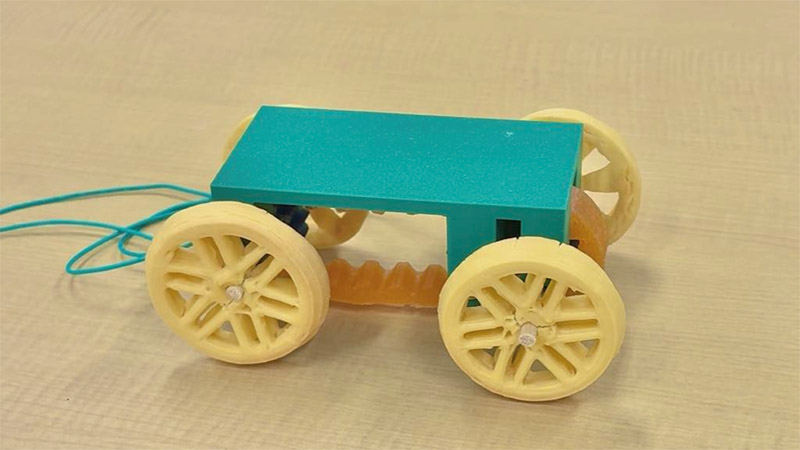
Edible mobile robot
1. Introduction
Edible robots, which involve replacing conventional structural materials such as metals and plastics with edible materials digestible by the human body, have garnered significant attention 1,2,3. These robots can leverage the unique advantages of edible materials depending on the application and operational environment. Examples include drug delivery robots that utilize biocompatibility for in vivo applications 4,5, reduce environmental footprints through biodegradability 6,7,8, and eliminate the risk of contamination by foreign matter in food processing facilities 9,10. Beyond these practical applications, recent research has focused on creating novel culinary experiences by imparting dynamic functionalities to food. As exemplified by the Japanese culinary tradition of odorigui (eating live seafood), the movement and lifelike qualities of food provide visual and tactile feedback, evoking specific psychological and cognitive processes that enrich the comprehensive dining experience 11. Intentional movements can be bestowed upon food by integrating edible materials with locomotion mechanisms, enabling unprecedented human–food interaction 12,13.
However, realizing autonomous edible mobile robots presents significant mechanical and control challenges, which stem from the flexibility and viscoelasticity of edible materials, and cause energy loss and uneven contact pressure due to material deformation when transmitting the driving force of the motor to the ground. Three-dimensional (3D) food printers (3DFPs) have been utilized to overcome these issues and enable flexibly designing and fabricating edible components with the desired geometries and functionalities 14. 3D printing has been extensively applied in robotics manufacturing and is indispensable for designing customized parts, prototypes, and complex structures such as robotic exoskeletons, arms, and grippers 15. Using 3DFPs enables creating personalized meals with tailored nutrition, enhances the visual appeal of alternative protein sources, supports automated food preparation, and reduces food waste 16,17,18. Moreover, selecting materials that exhibit appropriate fluidity during the printing process and possess sufficient mechanical strength to maintain structural integrity even after heating is crucial for the food inks employed in extrusion-based 3DFPs 19,20.
In the locomotion mechanism, the wheel is one of the most critical components, playing a vital role in safe driving, stable handling, and ride comfort 21. When using flexible edible materials for the wheels, controlling the deformation and fracture caused by the aforementioned viscoelasticity is important 22. Using 3DFPs enables fabricating edible wheels with complex internal structures that are difficult to manufacture using conventional processes. Typically, 3D-printed parts made of flexible materials differ in their internal geometric structures, which significantly affects the stress distribution, load-bearing characteristics, and fracture behavior 23,24. Therefore, we leveraged the design freedom of 3DFP in this study to fabricate multiple wheel shapes and evaluated the differences in their mechanical properties and durability. These findings, and optimizing the shape per the locomotion environment, may lead to future improvements in the driving performance of edible mobile robots.
We investigated fabricating a mobile robot with an edible shape design using molds and a screw-type 3DFP. Mold-cast gummy and candy were applied to the drive mechanism components, such as gears and axles, to enhance the edibility of the robot. A rice flour-based cookie dough was selected as the food ink for the 3DFP owing to its dimensional stability and shape retention after heating. First, rheological measurements were conducted to evaluate the suitability of the material as a food ink by analyzing its flow characteristics. Subsequently, the wheels comprising four distinct internal structures (i.e., spoke, mesh, fin, and dish) were fabricated, and their texture analyzed to assess the mechanical strength of the printed objects. Finally, the fabricated edible components were assembled, and the locomotion experiments were performed to verify the feasibility of the proposed drive mechanism (Fig. 1).
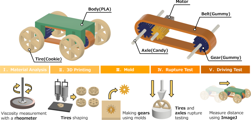
Fig. 1. Overview of an edible mobile robot.
2. Mobile Robot with Edible Shape Design
2.1. System Configuration and Drive Mechanism of the Edible Mobile Robot
The mobile robot proposed in this study employed a four-wheel-drive (4WD) system to ensure reliable propulsion. Fig. 2 shows an overview of the edible mobile robot featuring a hybrid structure comprising edible and non-edible components. The tires in contact with the road surface, gears and timing belt for the power transmission, and axles supporting the vehicle body were fabricated from edible materials. Meanwhile, the body, which serves as the structural foundation, was fabricated from 3D-printed polylactic acid (PLA), with external dimensions of 114 mm (length), 60 mm (width), and 40 mm (height). Additionally, a low-speed, high-torque motor (operating voltage: 3 V, rotational speed: 15 rpm) was utilized as the power source. As the drive principle, the output power from the motor was initially transmitted to an edible gear fixed to one of the axles. Furthermore, the gears mounted on both the front and rear axles were connected via a timing belt made of an edible material, thereby distributing the driving force of the motor to all the wheels and enabling the synchronous rotation of the four wheels.
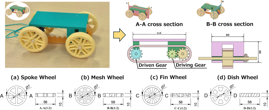
Fig. 2. Overview of the edible mobile robot and the four types of wheel designs: (a) spoke wheel, (b) mesh wheel, (c) fin wheel, and (d) dish wheel. All dimensions are given in mm.
2.2. Material Selection and Component Fabrication Processes
The components of the robot were manufactured using materials and processes selected according to the mechanical requirements. First, the gears and timing belt for power transmission were fabricated by pouring a gummy solution into silicone molds, and subsequently cooled and solidified. This gummy solution was formulated using gelatin (Cook Gelatin, Morinaga & Co., Ltd., Japan), glycerin (Vegetable Glycerin, Amazing Craft Co., Ltd., Japan), water, and citric acid (Food Additive Citric Acid, Kenei Pharmaceutical Co., Ltd., Japan) at a mass ratio of \(2.0 : 1.5 : 2.5 : 0.2\).
Specifically, a gear train with a reduction ratio of 1.2, consisting of a 12-tooth driven gear (blue, pitch circle diameter: 24 mm) and a 10-tooth driving gear (yellow, pitch circle diameter: 20 mm), based on the standard Module 2 specifications, was arranged with a center distance of 100 mm (Fig. 3(a)). Additionally, a timing belt with 40 teeth, width of 18 mm, and circumference of approximately 269.2 mm was fabricated (Fig. 3(b)).
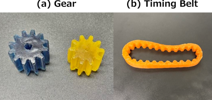
Fig. 3. Gummy-based power transmission mechanism fabricated by molding: (a) arrangement of the driving and driven gears, (b) appearance of the timing belt.
The axles, which support the weight of the robot and are subjected to torsional stress, require higher mechanical strength; therefore, a hard candy (“Okuchi Sukkiri Washu Hakka Nodo Ame,” Asahi Group Foods, Ltd., Japan) was selected. The candy was melted using a microwave oven (500 W) for 90 to 120 seconds, poured into an axle mold, and then cooled to solidify.
As the tires directly contact the road surface and support the loads and impact, additive manufacturing was applied via a 3DFP, using cookie dough as food ink. After 3D printing, the fabricated wheels were baked in an oven at 150 °C for 12 minutes. The 3DFP allows fabricating fine structures and complex internal geometries that are difficult to mold using conventional casting methods. Moreover, as a wide variety of wheel geometries can be fabricated by modifying the parameters in the 3D computer-aided design model, this approach facilitates optimizing the wheel morphology for different road surface conditions.
2.3. Properties and Formulation of the Food Ink in 3D Food Printing
The properties of the food ink must be highly compatible with the screw-extrusion 3DFP to fabricate the complex internal structures of the tires (discussed in Section 2.2) accurately and obtain a durable and practically usable product. Specifically, the ink should exhibit a stable fluidity suitable for extruding from the nozzle during the printing process, and transforming into a solid, with sufficient mechanical strength to support the vehicle body, after heating. These irreversible physical changes induced by heating enhance the adhesion between the deposited ink layers, ultimately determining the durability of the final printed object. In this study, a rice flour-based cookie dough was selected as the material due to its excellent dimensional stability and shape retention subsequent to heating. Furthermore, the optimal rheological properties that achieve both the extrusion stability in 3DFP and mechanical strength of the printed object were explored by varying the amount of the base rice flour at three levels: 60 g, 65 g, and 70 g. For each portion of rice flour, 30 g of sugar, 30 g of rice oil, and one whole egg were added, and the ingredients were uniformly kneaded using a mixer. This standardized formulation and mixing procedure ensured preparing the food ink with high reproducibility.
2.4. Internal Structure of the Edible Wheels
Four types of wheels, i.e., (a) spoke, (b) mesh, (c) fin, and (d) dish (Fig. 2) were designed for fabrication using the prepared food ink.
-
(a)
The spoke wheel features a structure connecting the central hub and the outer rim with radial members, which ensures lightweight characteristics and shock absorption through moderate flexibility.
-
(b)
The mesh wheel consists of mesh-like members arranged between the hub and the rim. This design alleviates the localized stress caused by external forces and distributes the loads along multiple directions.
-
(c)
The fin wheel incorporates diagonal or curved blade-like protrusions relative to the direction of travel, imparting specific bending stiffness and stress transmission in the rotational direction.
-
(d)
The dish wheel features a structure wherein the central hub is substantially expanded toward the outer periphery, with thick supporting members reinforcing the rim.
Fabricating these four designs using 3DFP and measuring their mechanical strengths via texture analysis enabled quantitatively evaluating the impact of differences in the internal structures on the durability of the edible wheels.
3. Experiment Overview
3.1. Evaluating the Rheological Properties of the Food Ink
The rheological properties of the rice flour-based food ink were measured using an MCR302 rheometer (Anton Paar, Austria) to evaluate its printability. Typically, these properties significantly affect the extrusion stability and printing accuracy in screw-extrusion 3DFP. A parallel plate with a diameter of 25 mm and a gap height of 1 mm was used for the measurements, and cookie doughs with three levels of rice flour content (i.e., 60 g, 65 g, and 70 g) were evaluated.
First, a strain sweep was conducted as a dynamic viscoelastic measurement to determine the linear viscoelastic region (LVR) over a strain range of 0.01% to 150% under steady conditions, at a temperature of 25 °C and a frequency of 1 Hz. Thus, the storage modulus (\(G'\)) and loss modulus (\(G''\)) were measured, and the structural integrity and energy dissipation characteristics of the ink were evaluated to verify its capability for structural recovery after applying stress. Furthermore, a frequency sweep measurement was performed in the range of 0.1 Hz to 100 Hz to calculate the apparent viscosity. These analyses revealed the correlation between the microstructure of the ink and its recovery upon releasing the stress, providing crucial insights for evaluating its suitability for the 3D printing process.
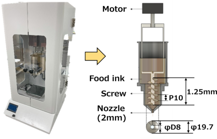
Fig. 4. 3D food printer: FP-3000.
3.2. Verification of the Printing Accuracy of the 3DFP
Printing experiments using a 3DFP were conducted, based on the rheological evaluation, to compare the differences in the printing accuracy between the various ink formulations. The 3DFP (FP-3000, Seiki Co., Ltd., Japan) used in this experiment is shown in Fig. 4. This machine features a mechanism that continuously extrudes the material from a syringe via a motor-driven screw, rendering it highly suitable for the stable additive manufacturing of highly viscous paste-like foods. Although the printer is equipped with a dual-nozzle mechanism that enables two-color printing, only a single nozzle was utilized in this study. The printing speed was 5000 mm/s, and the nozzle diameter was 1.0 mm. A cube measuring \(\textrm{25~mm} \times \textrm{25~mm} \times \textrm{25~mm}\) was printed to assess the shape retention immediately after printing and after heating.
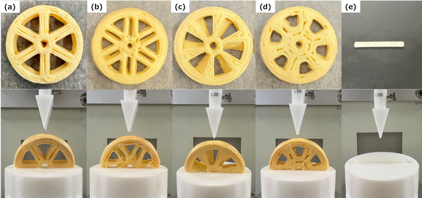
Fig. 5. Mechanical strength evaluation of the edible wheels and axles: (a) spoke wheel, (b) mesh wheel, (c) fin wheel, (d) dish wheel, and (e) axle.
3.3. Mechanical Strength Evaluation of the Edible Wheels and Axles
The ink formulation that exhibited the highest shape retention in the printing accuracy evaluation (Section 3.2) was adopted as the material for fabricating the tires. The wheels featuring the four types of internal structures were all fabricated with a thickness of 5 mm using 3DFP. In addition, the axles were fabricated via mold-casting using candy. Fracture tests were conducted using a creep meter (RE2-33005C, Yamaden Co., Ltd., Japan) to evaluate the durability of the fabricated edible wheels and axles quantitatively. The experimental setup of the fracture test is shown in Fig. 5.
The 3D-printed edible wheels were cut in half along the plane passing through the central axis to prepare semi-circular specimens to observe the deformation and fracture behavior of the internal structures accurately and, thus, evaluate the tires. During the testing, each specimen was placed on the testing stage with the flat cut surface facing downward, and a compressive load was applied radially to the outer circumferential surface of the wheel toward the center. By contrast, the load was applied perpendicularly to the longitudinal axis of the cylindrical axle specimens (diameter: 5 mm, length: 40 mm) fabricated via molding. A wedge-shaped plunger with tip dimensions of \(\textrm{1~mm} \times \textrm{30~mm}\) was employed as the loading jig, and compressed using a 200 N load cell at a constant speed of 10 mm/s until it fractured. Three trials were conducted for each specimen to ensure data reliability and reproducibility. The obtained mechanical responses were plotted as load-strain curves, and the average fracture loads resulting from the different internal structures were compared and evaluated.
3.4. Driving Test of the Edible Mobile Robot
A prototype of a 4WD edible mobile robot was constructed by assembling the gummy gears and timing belt fabricated using silicone molds, candy axles, and 3D-printed cookie tires onto a PLA body. Furthermore, the assembly of the robot and the driving tests were conducted immediately after demolding the edible components to minimize the effects of moisture evaporation and shrinkage over time in edible materials such as the gummy.
Based on the design specifications of the installed motor (driving voltage: 3 V, no-load rotational speed: 15 rpm) and the tire diameter (56 mm), the theoretical ideal propulsion speed was calculated assuming no losses such as slippage in the power transmission mechanism. The theoretical ideal propulsion speed, \(V_{\mathrm{ideal}}\) [mm/s], was calculated using the following equation, with the motor rotational speed \(N_m\) [rpm], the gear ratio \(R\), and the outer tire diameter \(D\) [mm]:
The driving behavior of the robot was video-recorded to evaluate its propulsion quantitatively, and was analyzed using an image processing software (ImageJ). Thus, the displacement was tracked over time using the trajectory of the robot, and the average moving speed was calculated.
4. Results and Discussion
4.1. Rheological Properties of the Food Ink
The dynamic viscoelasticity and apparent viscosity measurements are shown in Fig. 6. From the strain sweep measurements shown in Fig. 6(a), the limit of the LVR of the ink was confirmed to be at a strain of less than 1%. Within the LVR, the storage modulus (\(G'\)) exceeds the loss modulus (\(G''\)), and elastic behavior dominates, because the strain is sufficiently small and does not disrupt the physical structure of the material. However, beyond the LVR, the deformation of the material induces a significant decrease in both \(G'\) and \(G''\); when \(G''\) exceeds \(G'\), the ink exhibits a liquid-like flow behavior. Among the three levels compared, the ink formulated with 70 g of rice flour exhibited the highest \(G'\) and \(G''\), indicating that it possessed a robust network structure.
Furthermore, in the apparent viscosity measurements shown in Fig. 6(b), a thixotropic property, wherein the viscosity exhibits an exponential decay, was confirmed in all the formulations. The ink with 70 g of rice flour demonstrated a clear shear-thinning behavior despite having a high initial viscosity. This observation indicates that the ink fluidizes under the shear stress exerted by the 3DFP screw, enabling smooth extrusion, and recovers its original solid-like structure once the stress is released (after passing through the nozzle). In other words, this demonstrates that the rotation of the screw in the 3DFP effectively reduces the viscosity, thereby enabling the extrusion of the ink.
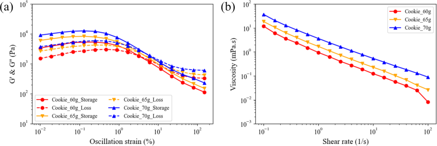
Fig. 6. Graphical representation of the rheological properties of the food inks: (a) strain sweep illustrating the linear viscoelastic range, (b) apparent viscosity depicting the flow characteristics.
4.2. Verification of Printing Accuracy Using a 3D Food Printer
The impact of the differences in the rheological properties on the actual printing accuracy is shown in Fig. 7. Due to its high storage modulus (\(G'\)), the ink formulated with 70 g of rice flour could support its own weight and maintained the shape of a \(\textrm{25~mm} \times \textrm{25~mm} \times \textrm{25~mm}\) cube even after printing. By contrast, the inks with 60 g and 65 g of rice flour had relatively lower viscosities and moduli, and slumped immediately after printing, which made retaining the 3D complex shapes difficult. Optimizing the post-printing shape retention and extrusion characteristics is essential to achieve the necessary printing accuracy. These results demonstrated that the formulation using 70 g of rice flour is the optimal material for fabricating the targeted internal structures of the wheels.
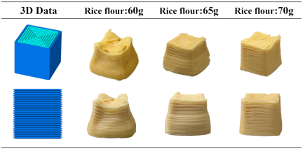
Fig. 7. Comparison of moldability in 3D printing using the food inks with different rice flour ratios.
4.3. Mechanical Strength Evaluation of Edible Wheels and Axles
Compressive fracture tests were conducted on the four types of edible tires fabricated via 3DFP (containing 70 g of rice flour) and mold-cast candy axles to evaluate the mechanical strength of the edible parts constituting the robot quantitatively. The average load-strain curves from three trials for each sample are shown in Fig. 8. Additionally, the statistical data regarding the mass and maximum fracture load from the three trials (\({n=3}\)) for each sample are summarized in Tables 1 and 2.
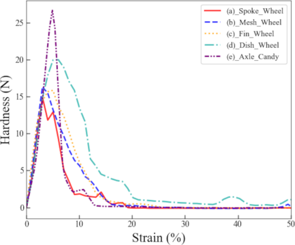
Fig. 8. Load–strain curves obtained from the compressive fracture tests.
| Wheel design | Weight (mean \(\pm\) SD) [g] |
| Spoke wheel | 15.1(3.3) |
| Mesh wheel | 15.6(3.2) |
| Fin wheel | 14.8(3.9) |
| Dish wheel | 16.6(3.2) |
| Edible component | Maximum load (mean \(\pm\) SD) [N] |
| Spoke wheel | 14.9(4.0) |
| Mesh wheel | 16.3(1.9) |
| Fin wheel | 15.9(3.4) |
| Dish wheel | 20.0(3.0) |
| Axle | 26.7(8.2) |
In the wheel tests, all samples reached their yield points at a strain of less than 10%. Comparing the maximum loads of the average curves shows that the dish wheel exhibited the highest value among the four types at 20.0 N. The dish wheel features a structure wherein the central hub is significantly expanded toward the outer periphery, and the members supporting the rim are thickened. The measurement results (Table 1) suggest that it has the maximum mass (16.6 g), and a high volumetric fill ratio for its shape. This dense material distribution ensures a large effective cross-sectional area, which is considered the primary factor underpinning its extremely high rigidity.
By contrast, the spoke wheel recorded the lowest maximum load at 14.9 N. A structure extending linearly from the hub to the rim, such as that of the spoke wheel, tends to concentrate compressive loads on specific struts. The spoke wheel likely fractured abruptly because its structure was unable to effectively distribute the applied load.
Furthermore, the mesh wheel and the fin wheel exhibited maximum loads of 16.3 N and 15.9 N, respectively. Compared to the spoke wheel, a more gradual load decrease leading up to the fracture was observed in these models. The structures of the mesh and fin wheels likely avoided direct buckling under compression and dispersed the load through the bending deformation of the members, thereby contributing to the gradual fracture behavior.
Moreover, in terms of the maximum fracture load relative to the mass of each shape, the lightest fin wheel (14.8 g) demonstrated higher strength than the heavier spoke wheel (15.1 g). This suggests that the diagonal structure of the fins can support and disperse compressive loads more efficiently, with less material volume, compared to a simple linear radial structure.
The measured fracture loads were compared with the estimated service load to assess whether the fabricated wheels possessed sufficient mechanical strength for practical operation. The total mass of the prototype was 120 g (1.18 N); assuming it is supported equally by the four wheels, the static load applied to each wheel is approximately 0.29 N. However, when operating in actual environments, dynamic and impact loads act on the wheels due to road surface irregularities and acceleration or deceleration. Furthermore, variations in the payload must be anticipated for future applications, such as carrying nutrients or sensors. Therefore, accounting for these fluctuating loads is necessary when designing the wheels. The maximum fracture loads of each wheel measured in this test (14.9–20.0 N) significantly exceeded this static load (0.29 N). Consequently, the fabricated wheels demonstrate a sufficient safety margin for practical operation even considering the dynamic and fluctuating loads.
Next, the stress on the candy axle increased linearly until reaching a maximum load of 26.7 N at a strain of approximately 5%–7%, exhibiting typical brittle fracture behavior where the load dropped sharply at the moment a crack was initiated. As is evident from the comparison in Fig. 8, the candy axle possesses higher rigidity than the cookie wheels, confirming that it has sufficient load-bearing capacity to support the weight of the robot.
However, the brittle nature quantitatively demonstrated in this test suggests a risk of sudden fracture when an impact load exceeding its limit is applied—such as encountering a bump during locomotion—or when the stress is concentrated on the microscopic surface flaws generated during molding. Therefore, adopting a structure that encapsulates a flexible material, such as gummy, as a core is considered effective to enhance the durability of future edible mobile robots. This approach would impart toughness and suppress brittle fracture while maintaining the high rigidity of the candy.
4.4. Driving Test of the Edible Mobile Robot
The propulsion test of the assembled edible mobile robot is shown in Fig. 9. The preliminary evaluations conducted for selecting the tires for this experiment confirmed that, under the driving conditions of the robot and on a flat road surface, the differences in the internal structure of the tire did not result in any significant difference in the straight-line propulsion speed. Therefore, a representative shape with average weight and mechanical strength characteristics was adopted for the propulsion test to ensure the validity of the experimental model and the reliability of the results, instead of selecting a shape that excelled only in a specific performance metric.
Based on Tables 1 and 2, the overall average mass and maximum fracture load for the four types of wheels are 15.5 g and 16.8 N, respectively. The measurement results for the mesh wheel (mass: 15.6 g, maximum load: 16.32 N) indicate that it possessed the average characteristics among the four designed edible wheels in terms of both weight and mechanical strength. Furthermore, the mesh wheel exhibited the smallest variation in fracture load (standard deviation: \({\pm}1.85\) N) among the four types, demonstrating superior structural stability. For these reasons, the mesh wheel was adopted as the representative shape for the propulsion tests.
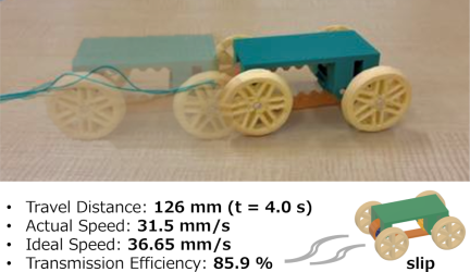
Fig. 9. Driving test results of the edible mobile robot.
Per the propulsion test, the output power from the motor was successfully transmitted to the front and rear axles via the gummy gears and the timing belt, confirming continued propulsion using the four-wheel drive system.
In this experiment, the robot traveled a distance of \(\Delta x = 126\) mm over a duration of \(\Delta t = 4.0\) s. The measured average propulsion speed \(V_{\mathrm{actual}}\) [mm/s] is defined by the following equation:
Here, the power transmission efficiency \(\eta\) [%] is defined as the ratio of the measured speed to the theoretical ideal propulsion speed (\(V_{\mathrm{ideal}} = 36.65\) mm/s), as expressed in the following equation:
This propulsion loss can be attributed to four primary factors. First, the power transmission efficiency was highly dependent on the tension of the gummy belt, and slippage occurred between the gears and the belt when the tension weakened. As shown in Table 2, the maximum fracture load of the candy axle is \(26.7{\pm}8.2\) N. The initial tension had to be minimized to prevent the fracture of the axles. This design constraint led to the inability to maintain a sufficient tension during driving, consequently causing the slippage. Second, due to the one-sided support of the motor-side gear, the design allowed the force to escape when a high load was applied, as the motor-side gear yielded to the reaction force from the axle gear. Third, when driving, the tension of the belt pulled the axles, generating a significant frictional resistance at the contact areas between the axles and the PLA body, which hindered the propulsion. Fourth, the inherent surface tackiness of the gummy material resulted in adhesion at the meshing points between the gears and the timing belt, which temporarily impeded a smooth rotational motion.
Thus, the elasticity of the gummy material induced minute deformations in the gear teeth and friction, resulting in a transmission loss of 14.1%. However, the primary motivation for selecting gummy as the material for the gears and belt in this robot was prioritizing its material toughness to prevent catastrophic failure of the entire system. If brittle materials such as cookies or candy were used, the high stress concentration at the gear meshing points would pose a significant risk of sudden tooth chipping or fracture. Therefore, this design adopted a gummy formulated with a high gelatin content to optimize its hardness as a gear while maintaining sufficient flexibility to withstand these stresses.
Edible bearings and edible lubricants should be introduced to address these issues and improve the transmission efficiency to the ideal value, besides reinforcing the support structure of the motor gear. Furthermore, applying a powder coating, such as potato starch, to the axle surfaces to reduce the friction coefficient can be extremely effective in improving the driving performance of future edible mobile robots. From the material design perspective, developing composite edible materials is a key future prospect. For instance, approaches such as adding dietary fibers to the gummy base to increase the elastic modulus while retaining its toughness, or employing a hybrid structural design—using hard candy as a rigid core and coating only the gear teeth surfaces with a thin gummy layer for shock absorption—could achieve an optimal balance between the transmission efficiency and durability.
5. Conclusions
In this study, we investigated a method for fabricating a mobile edible robot by combining screw-extrusion 3DFP and molding techniques. In the rheological measurements to verify the suitability of the food ink, the material exhibited shear-thinning characteristics suitable for extrusion printing, thereby demonstrating its applicability for 3D printing. Furthermore, four wheel designs with different internal structures were fabricated to evaluate the mechanical strength and texture of the printed objects, and texture measurements were conducted. The results revealed that the rigidity and durability vary depending on the geometric design, providing useful guidelines for optimizing the locomotion mechanism. Additionally, the drive system components, such as gears, belts, and axles, were fabricated using molds, and by integrating these parts, we succeeded in prototyping a four-wheel-drive edible mobile robot.
Although the driving tests revealed mechanical challenges including gummy belt slippage caused by insufficient tension, unstable gear meshing due to the cantilevered motor structure, and friction between the axles and the body, this study demonstrates the feasibility of constructing robots from food-derived materials and provides a foundation for reducing the environmental impact of robotic systems. In particular, balancing food safety with robotic functionality is expected to contribute to the establishment of a new design foundation in the field of edible robotics.
Future work includes further shape optimization and the improvement of the power transmission mechanism to enhance the durability and practicality of the edible robot. Specifically, in addition to improving the materials and shapes of the belts and gears, we aim to implement friction-reducing designs, such as applying a powder coating to the axle surfaces. Moreover, by changing the support structure of the pinion gear connected to the motor from a cantilevered to a dual-support configuration, we plan to drastically improve durability and advance research toward practical implementation.
Furthermore, quantitatively evaluating the cost of transport by monitoring the electrical power input from an external energy source is a critical task for our future work. Such energy efficiency assessments will provide essential metrics for further optimizing the edible locomotion mechanism and enhancing its practical viability.
Additionally, by utilizing the dual-nozzle mechanism of the 3DFP, we envision expanding to multi-material printing in the future, combining multiple edible materials with different mechanical properties. This will not only improve the overall mechanical strength of the structure but also enable the arbitrary control of rigidity and flexibility in specific areas such as locally allocating hard and soft materials depending on the application and required functions. Finally, by expanding the range of applicable food materials and enabling nutrient customization, this technology is expected to contribute to diverse fields, including medical applications, sustainable food production, and nutritional supply through the use of the robot itself as food at disaster sites.
Acknowledgments
We would like to express our gratitude for the financial support provided by the following organizations and programs: the New Energy and Industrial Technology Development Organization (NEDO) for projects JPNP14004 (Feasibility Study), JPNP20004 (Young Researcher), JPJ012495 (SIP2), and JPNP23025 (SIP3); the Japan Society for the Promotion of Science (JSPS) for Grants-in-Aid for Scientific Research JP17H01224, JP18H05471, JP19H01122, JP21H04936, and JP21K14040; the Japan Science and Technology Agency (JST) for JPMJCE1314 (COI), JPMJOP1844 (OPERA), and JPMJOP1614 (OI-OPERA); and the Cabinet Office, Government of Japan, Moonshot Program of MAFF for MS508 and MS511.
- [1] R. Kanno, B. Kwak, M. Pankhurst, J. Shintake, and D. Floreano, “Edible soft actuators based on konjac glucomannan for underwater operation,” Adv. Intell. Syst., Vol.6, No.5, Article No.2300473, 2024. https://doi.org/10.1002/aisy.202300473
- [2] B. Kwak, J. Shintake, L. Zhang, and D. Floreano, “Towards edible drones for rescue missions: Design and flight of nutritional wings,” 2022 IEEE/RSJ Int. Conf. Intell. Robots Syst. (IROS), pp. 1802-1809, 2022. https://doi.org/10.1109/IROS47612.2022.9981956
- [3] D. Floreano et al., “Towards edible robots and robotic food,” Nat. Rev. Mater., Vol.9, No.8, pp. 589-599, 2024. https://doi.org/10.1038/s41578-024-00688-9
- [4] L. Lamanna, P. Cataldi, M. Friuli, C. Demitri, and M. Caironi, “Monitoring of drug release via intra body communication with an edible pill,” Advanced Materials Technologies, Vol.8, No.1, Article No.2200731, 2022. https://doi.org/10.1002/admt.202200731
- [5] D. Shen, M. Zhang, A. S. Mujumdar, and J. Li, “Advances and prospects for edible robots based on additive manufacturing technology,” Innov. Food Sci. Emerg. Technol., Vol.100, Article No.103896, 2025. https://doi.org/10.1016/j.ifset.2024.103896
- [6] R. Kanno et al., “Biodegradable electrohydraulic soft actuators,” Adv. Intell. Syst., Vol.5, No.9, Article No.2200239, 2023. https://doi.org/10.1002/aisy.202200239
- [7] V. F. Annese et al., “An edible bistable tilt sensor enabling autonomous operation of a partially eatable rolling robot,” Adv. Sens. Res., Vol.2, No.12, Article No.2300092, 2023. https://doi.org/10.1002/adsr.202300092
- [8] D. Rus and M. T. Tolley, “Design, fabrication and control of soft robots,” Nature, Vol.521, No.7553, pp. 467-475, 2015. https://doi.org/10.1038/nature14543
- [9] J. Trafialek, S. Kaczmarek, and W. Kolanowski, “The risk analysis of metallic foreign bodies in food products,” J. Food Qual., Vol.39, No.4, pp. 398-407, 2016. https://doi.org/10.1111%2Fjfq.12193
- [10] J. Yao, Z. Wu, P. Wang, J. Ye, and J. Wang, “Research on X-ray image fusion algorithm for food foreign object detection,” J. Nondestruct. Eval., Vol.44, No.2, Article No.63, 2025. https://doi.org/10.1007/s10921-025-01203-y
- [11] Y. Nakata et al., “Exploring the eating experience of a pneumatically-driven edible robot: Perception, taste, and texture,” PLOS One, Vol.19, No.2, Article No.e0296697, 2024. https://doi.org/10.1371/journal.pone.0296697
- [12] T. Gayler, “Towards edible interfaces: Designing interactions with food,” Proc. 19th ACM Int. Conf. Multimodal Interact., pp. 623-627, 2017. https://doi.org/10.1145/3136755.3137030
- [13] E. Van Doleweerd and M. B. Alonso, “The creation of a holistic interactive dining experience with shape-changing food materials at restaurant alchemist,” Proc. 17th Int. Conf. Tangible Embed. Embodied Interact., Article No.21, 2023. https://doi.org/10.1145/3569009.3572791
- [14] Y. Igeta, K. Fujiwara, J. Ogawa, and H. Furukawa, “Anisotropic texture control in 3D food printing through pitch adjustment and internal structural design,” Artif. Life Robot., Vol.30, No.4, pp. 786-793, 2025. https://doi.org/10.1007/s10015-025-01065-7
- [15] G. L. Goh, H. Zhang, T. H. Chong, and W, Y, Yeong, “3D printing of multilayered and multimaterial electronics: A review,” Adv. Electron. Mater., Vol.7, No.10, Article No.2100445, 2021. https://doi.org/10.1002/aelm.202100445
- [16] H. Jiang et al., “3D food printing: Main components selection by considering rheological properties,” Crit. Rev. Food Sci. Nutr., Vol.59, No.14, pp. 2335-2347, 2019. https://doi.org/10.1080/10408398.2018.1514363
- [17] J. Sun, Z. Peng, L. Yan, J. Y. H. Fuh, and G. S. Hong, “3D food printing—An innovative way of mass customization in food fabrication,” Int. J. Bioprinting, Vol.1, No.1, pp. 27-38, 2015. https://doi.org/10.18063/IJB.2015.01.006
- [18] F. Yang, M. Zhang, S. Prakash, and Y. Liu, “Physical properties of 3D printed baking dough as affected by different compositions,” Innov. Food Sci. Emerg. Technol., Vol.49, pp. 202-210, 2018. https://doi.org/10.1016/j.ifset.2018.01.001
- [19] R. Karyappa and M. Hashimoto, “Chocolate-based ink three-dimensional printing (Ci3DP),” Sci. Rep., Vol.9, No.1, Article No.14178, 2019. https://doi.org/10.1038/s41598-019-50583-5
- [20] J. I. Lipton, “Printable food: The technology and its application in human health,” Curr. Opin. Biotechnol., Vol.44, pp. 198-201, 2017. https://doi.org/10.1016/j.copbio.2016.11.015
- [21] X. Wan, Y. Shan, X. Liu, H. Wang, and J. Wang, “Simulation of biaxial wheel test and fatigue life estimation considering the influence of tire and wheel camber,” Adv. Eng. Softw., Vol.92, pp. 57-64, 2016. https://doi.org/10.1016/j.advengsoft.2015.11.005
- [22] Y. Ma, M. A. I. Schutyser, R. M. Boom, and L. Zhang, “Quantification of fracture mechanics with digital image correlation guides the infill design of 3D-printed snack bars with modulated flexural properties,” Virtual Phys. Prototyp., Vol.19, No.1, Article No.e2349679, 2024. https://doi.org/10.1080/17452759.2024.2349679
- [23] R. Maldonado-Rosas, J. L. Pérez-Castillo, E. Cuan-Urquizo, and V. Tejada-Ortigoza, “The role of controlled voids shape on the flexural properties of 3D printed food: An approach for tailoring their mechanical properties,” Virtual Phys. Prototyp., Vol.19, No.1, Article No.e2284816, 2024. https://doi.org/10.1080/17452759.2023.2284816
- [24] A. Quattrocchi et al., “Measurement of the structural behaviour of a 3D airless wheel prototype by means of optical non-contact techniques,” Acta IMEKO, Vol.11, No.3, Article No.13, 2022. https://doi.org/10.21014/acta_imeko.v11i3.1268
- [25] N. T. Ukamaka and P. A. Onwualu, “Effect of moisture content and types of structural surfaces on coefficient of friction of two Nigerian food grains: Sorghum (Sorghum bicolor) and millet (Pennisetum glaucum),” Agric. Eng. Int.: CIGR J., Vol.11, Article No.1152, 2009.
This article is published under a Creative Commons Attribution-NoDerivatives 4.0 Internationa License.