
Paper:
Design and Fabrication of a Snake Robot Using Modular Pneumatic Film Actuators
Kaisei Takahashi*, Daisuke Yamaguchi**
 , Shuichi Wakimoto**
, and Takefumi Kanda**
*Graduate School of Environment, Life, Natural Science and Technology, School of Engineering, Okayama University
3-1-1 Tsushima-naka, Kita-ku, Okayama, Okayama 700-8530, Japan
**Division of Intelligent Mechanical Systems Course, Faculty of Environmental, Life, Natural Science and Technology, Okayama University
3-1-1 Tsushima-naka, Kita-ku, Okayama, Okayama 700-8530, Japan

Pipe inspection robots are being developed for environments that are difficult for humans to enter, such as nuclear power and chemical plants. However, the actuators used for robots are large and heavy, which limits the miniaturization of piping inspection robots. This paper presents an ultra-thin, lightweight film snake-type robot composed of polyimide (PI) film actuators. The proposed robot is expected to enable the easy transport of multiple units. By utilizing the heat and chemical resistance of PI, it can efficiently inspect various targets from multiple locations under harsh conditions. The robot employs a bidirectional bending differential stiffness actuator (BB-DSA). The BB-DSA has two air chambers formed by welding three non-stretchable PI films of different thicknesses. By changing the applied pneumatic pressure between the two air chambers, the actuator achieves bidirectional large bending deformation with a simple structure. A connectable actuator structure is also introduced to reduce the number of pneumatic supply tubes. This contributes to lowering the overall weight of the robot and improving its locomotion performance. The bending angle and generated force of the actuator were evaluated. In addition, a snake-type robot with a reduced number of tubes was fabricated, and its traveling speed and traction force were evaluated. The results show that the maximum traveling speed and traction force were 1.38 mm/s and 14.57 mN, respectively.
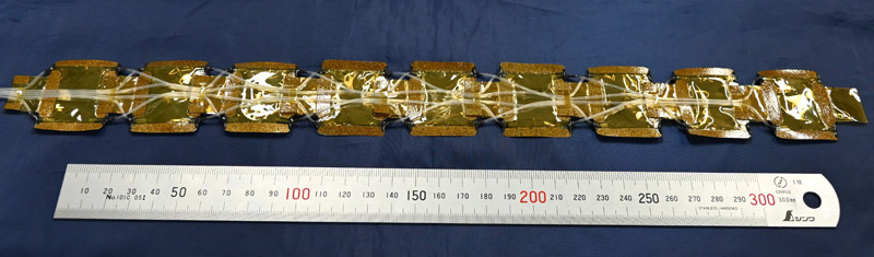
Snake-shaped robot made of PI films
1. Introduction
The aging of piping systems in nuclear power and chemical plants can lead to accidents; therefore, regular maintenance is required. However, many of these environments are difficult for humans to access. For this reason, pipeline inspection robots are introduced 1. Pipeline robots have several types of locomotion mechanisms. A wheeled robot moves by rotating its drive wheels 2,3,4,5. Compared with other mechanisms, it has the advantages of high traveling speed and durability. However, its drawback is that traction decreases in low-friction environments. A crawler-type robot moves by rotating a track driven by drive wheels 6,7,8. This provides high traction and enables stable movement. However, its structure is complex, making miniaturization difficult. A screw-drive robot moves forward and backward by rotating like a screw to travel through curved pipes without additional control 9,10,11. Its advantages include simple driving mechanism, ease of design, and suitability for miniaturization. However, the parts in contact with the pipe wall are prone to wear and require regular maintenance. An inchworm-type robot consists of two or more anchoring mechanisms that press against the pipe wall and one or more extension/contraction mechanisms 12,13,14. When pneumatic actuation is used, it has the advantage of excellent waterproof performance because no rotary mechanism is required. However, because its motion cycle includes stopping phases, the robot cannot move at a constant speed. In contrast, a snake robot consists of multiple connected units and moves by utilizing friction with the pipe wall and changes in joint angles 15,16,17,18,19. Compared with other driving methods, it has higher degrees of freedom and can perform various motion patterns. However, it tends to be large and heavy, and its control becomes complex.
In addition, many actuators used in pipeline robots are large and heavy, which has limited the miniaturization of pipeline inspection robots.
In our laboratory, we previously developed a differential stiffness actuator composed of a polyimide (PI) film, which has high environmental resistance 20. This actuator had a total length of 60 mm and a width of 32 mm and exhibited a maximum bending angle of 62.1° and a maximum generating force of 133.3 mN. However, it was not originally designed to be connected in series with multiple actuators to form a snake robot. Therefore, to realize a snake robot using this actuator, it is necessary to redesign the actuator while considering the connectivity between adjacent actuators.
In this study, a film actuator designed for connected use was realized, and a snake-type robot was developed. A differential stiffness actuator capable of bidirectional bending under pneumatic pressure was fabricated by welding three PI films, and its bending angle and generated force were evaluated. The fabricated actuators were connected to construct a snake-type robot with a reduced number of tubes, and its traveling speed and traction force were evaluated.
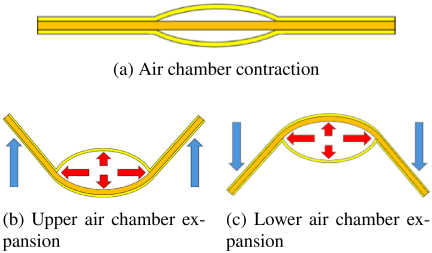
Fig. 1. Bidirectional bending differential stiffness actuator (BB-DSA).
2. Bidirectional Bending-Differential Stiffness Actuator (BB-DSA)
2.1. Overview of the Actuator
An overview of a bidirectional bending-differential stiffness actuator (BB-DSA) is shown in Fig. 1. Our laboratory uses a specialized technique for directly welding process for PI films 21. The welding is achieved by controlling the welding temperature, heat time, and applied pressure. The details of this process are described in the following section. By welding three PI films, a two-chamber structure was fabricated, as shown in Fig. 1(a). Because PI films do not elongate, when pneumatic pressure is applied to one of the air chambers, bending and generated force are produced by utilizing the difference in bending stiffness between the upper and lower films of the chamber.
2.2. Fabrication of the Actuator
The welding machine used for bonding the PI films operates by pressing a mold heated to a high temperature onto the PI films. A schematic of the welding device is shown in Fig. 2. The mold for actuator fabrication is shown in Fig. 3. The fabrication procedure of the actuator is shown in Fig. 4. First, three PI films were welded using the welding machine to form an air chamber. The mold temperature, applied pressure, and welding time were set to 560 °C, 0.2 MPa, and 120 s, respectively. Next, the fabricated air chamber was cut to the required actuator shape using scissors. Finally, silicone tubes for the air supply were attached to the upper and lower air chambers using a resin-based elastic adhesive to complete the actuator. The tubes with an outer diameter of 1 mm and an inner diameter of 0.5 mm were used. The tube had a mass per unit length of 0.7 g/m. It was confirmed that the tubing was sufficiently flexible so as not to affect the actuator’s motion.
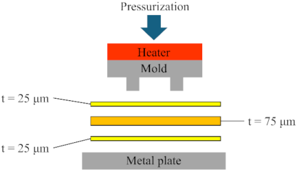
Fig. 2. Overview of the heating and pressurizing system.
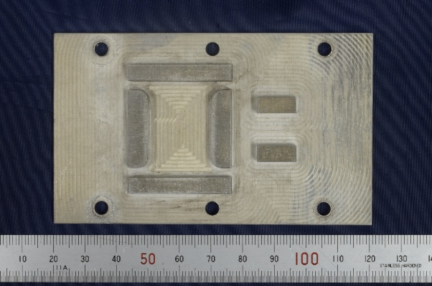
Fig. 3. Mold for actuator fabrication.
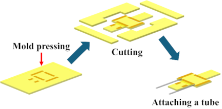
Fig. 4. Fabrication procedure of BB-DSA.
The fabricated BB-DSA is shown in Fig. 5. The air chamber was formed by welding one 75 μm-thick and two 25 μm-thick PI films. The actuator has an overall length of 90 mm and a width of 38 mm, while the air chamber measures \({30 \times 20}\) mm. The mass of the actuator was 0.41 g. When the actuator was used as a stand-alone unit, the two ends were sealed with an adhesive, as shown in Fig. 5. Furthermore, the use of a mold-based fabrication process ensured high reproducibility of the actuator.
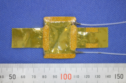
Fig. 5. Fabricated actuator overview.
In the previous actuator structure, it was necessary to connect the air supply tubes to use it as a snake-type robot, as shown in Fig. 6(a). As a result, the tubes could become significantly heavy relative to the robot. To reduce the number of tubes, four insertion holes were introduced. By connecting the tubes, the total tube length was reduced, as shown in Fig. 6(b). The two tubes connected to the actuator are bundled together by the welded section of the actuator support, as shown in Fig. 6(b).
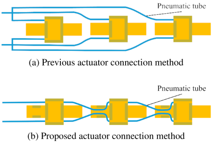
Fig. 6. Modification of the connection method.
2.3. Measurement of Bending Angle
The bending angle of the fabricated actuator was evaluated. The experimental setup for measuring the bending angle is shown in Fig. 7. To avoid restricting the actuator motion, the actuator was supported at the section immediately before the air chamber. The actuator was pressurized from 0 to 30 kPa. Its motion was recorded using a camera (Sony, FDR-AX30), after which the bending angle was measured using image analysis software (Mitani Corporation, WinROOF). For each pneumatic pressure condition, measurements were taken after the flow rate had stabilized at 0 mL/min. The bending angle \(\theta\) is defined as shown in Fig. 8. Pneumatic pressure was applied to the air chamber on the inner side of bending. The side of the air chamber that was in contact with the mold during welding was defined as the front side, while the opposite side was defined as the back side. Since the actuator was turned over for the back side measurement, the effect of gravity was the same for both the front side and back side measurements.
The relationship between the applied pressure and bending angle is shown in Fig. 9. The actuator is composed of extremely thin films and therefore provides little restoring force in the unpressurized state. As a result, it was slightly deformed from its original shape at the beginning of the experiment. Maximum bending angles of 98° on the front side and 99° on the back side were confirmed at an applied pressure of 30 kPa. These angles were sufficient to achieve the bending motion required for the sinusoidal driving described later. In addition, hysteresis was observed. This hysteresis is considered to be caused by the low restoring force of the film actuator. In this experiment, the air inside the chamber was not actively evacuated during depressurization. Because of the low restoring force, the air was not sufficiently discharged from the chamber, and some air remained trapped inside. Consequently, residual deformation occurred after depressurization, resulting in the observed hysteresis. Furthermore, because similar bending angles were obtained on both the front and back sides, stable bidirectional bending was achieved.
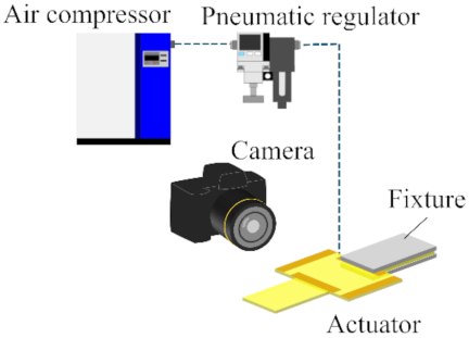
Fig. 7. Experimental configuration for bending angle measurement.
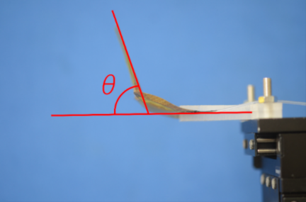
Fig. 8. Definition of bending angle.
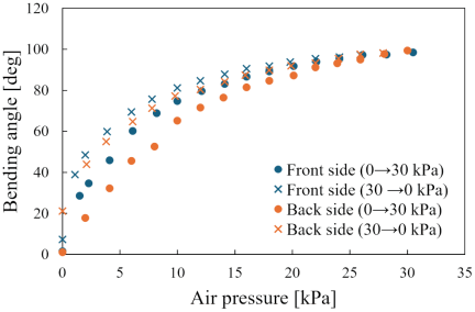
Fig. 9. Relationship between applied air pressure and bending angle.
2.4. Measurement of Generating Force
The relationship between the applied pressure and force generated by the fabricated actuator was evaluated. Unlike joint or link mechanisms that rotate about a single pivot, the proposed actuator generates motion through distributed bending of the entire structure. Therefore, the actuator performance was evaluated in terms of the generated force at the tip position, which is a commonly used metric for soft actuators. The experimental setup for measuring the generated force is shown in Fig. 10. The bending angles of the actuator were constrained to 0°, 30°, and 60°. A load cell (Kyowa, LTS-50GA) was placed perpendicular to the driving section. Pneumatic pressure from 0 to 30 kPa was applied, and the generated force was measured. For each pneumatic pressure condition, measurements were taken after the flow rate had stabilized at 0 mL/min. The measurement position for the generated force was set at 10 mm from the air chamber. The generating force measurement point is shown in Fig. 11. The states of the actuator constrained at each angle are shown in Fig. 12.
The relationship between the applied pressure and generated force is shown in Fig. 13. Maximum generated forces of 341.9 mN on the front side and 379.6 mN on the back side were confirmed at an applied pressure of 30 kPa. From these results, the actuator can generate a force in the order of several hundred millinewtons, suggesting that it has sufficient driving force for the propulsion of a snake-type robot. Similar generated forces were obtained on both the front and back sides. Therefore, stable bidirectional actuation and continuous bending motion can be achieved. In addition, hysteresis was observed. As with the bending angle characteristics, this hysteresis is considered to be caused by the low restoring force of the film actuator.
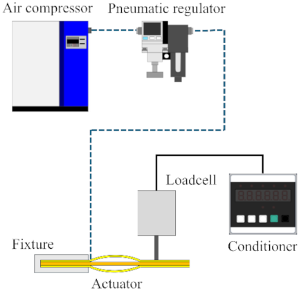
Fig. 10. Experimental configuration for generating force measurement.
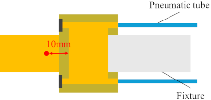
Fig. 11. Generating force measurement point.
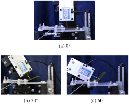
Fig. 12. Constraint at each bending angle.
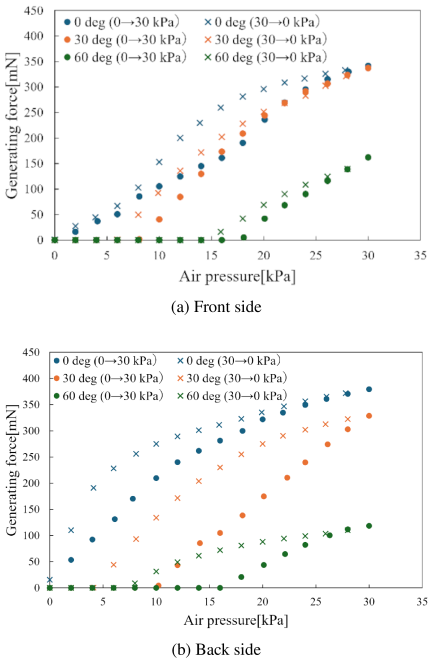
Fig. 13. Relationship between applied air pressure and generating force.
2.5. Measurement of Dynamic Characteristics
The dynamic characteristics of the fabricated actuator were evaluated. The experimental setup for the dynamic response measurement is shown in Fig. 14. A pneumatic pressure of 30 kPa was applied to the actuator for 5 s, followed by evacuation at \(-30\) kPa using a vacuum pump (Ulvac Kiko, Inc., G-50SA). The vacuum pump had a pumping speed of 60 L/min. The flow characteristics of the solenoid valve (Koganei Corporation, 030E1-PLL) had a maximum flow rate of 13 L/min at 100 kPa. The bending angle was measured using a motion capture system (OptiTrack, PrimeX 13).
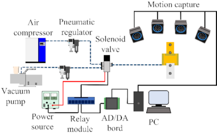
Fig. 14. Experimental configuration for dynamic characterization.
The step response of the actuator, including the vacuum pump and valves, is shown in Fig. 15. Portions of the data are missing due to a temporary loss of motion capture tracking. The measured time constants were 0.33 s and 0.32 s for the front side and back side, respectively. These results indicate that operation at higher switching frequencies would prevent the actuator from reaching the required bending angle before the next valve switching, thereby making stable locomotion of the snake-type robot difficult.
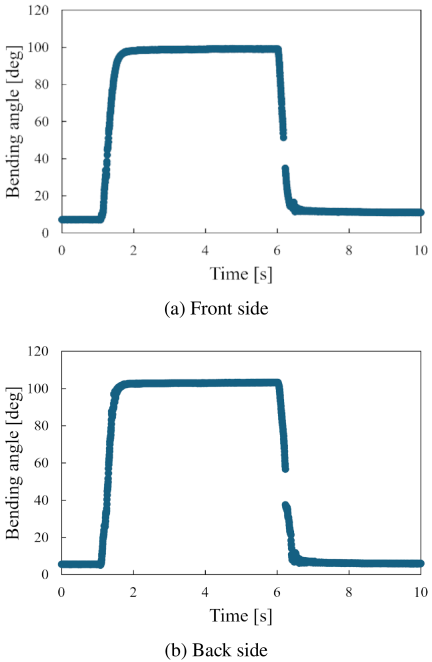
Fig. 15. Relationship between time and bending angle.
3. Fabrication of the Snake Robot
The snake robot was fabricated by arranging the developed actuators in series. The fabricated snake robot is shown in Fig. 16. The robot consists of nine actuators, each with a length of 60 mm. The overall length, width, and mass were 392 mm, 38 mm, and 5.3 g, respectively.
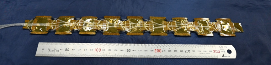
Fig. 16. Snake-shaped robot made of PI films.
3.1. Driving Principle of the Snake Robot
In this robot, the locomotion inside a pipeline is achieved using sinusoidal driving. The driving principle of sinusoidal motion is shown in Fig. 17. In sinusoidal driving, each joint of the robot composed of multiple units arranged in series is actuated with a phase difference, generating a sinusoidal wave along the entire body. The robot is propelled by the friction between its body and the pipe wall 22,23.
In this study, a sinusoidal wave was generated using six joints. The pneumatic input pattern applied to the snake robot is shown in Fig. 18. In the ON state, the actuator is connected to a compressor; in the OFF state, it is connected to a vacuum pump. The robot transitions through states S1–S12 and then returns to S1. One sequence from S1 to S12 was defined as one cycle. The time required for one cycle is defined as the driving period. The reciprocal of the driving period is defined as the driving frequency.
The robot was driven using these pneumatic input patterns. The motion of the robot during operation is shown in Fig. 19.
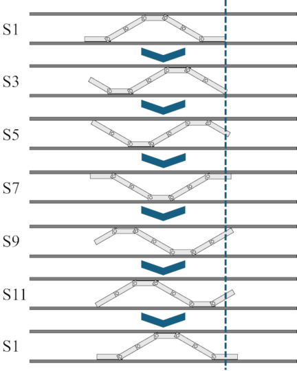
Fig. 17. Principle of sine wave drive.
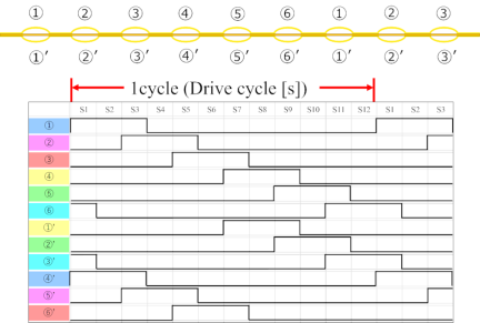
Fig. 18. Pneumatic pattern applied to the robot.
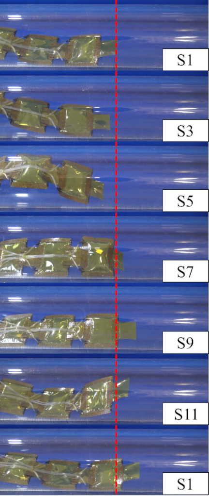
Fig. 19. Robot displacement per actuation cycle.
3.2. Evaluation of the Movement Speed of the Snake Robot
The driving system of the robot is shown in Fig. 20. The pneumatic pressure was supplied by a compressor and regulated using a pressure regulator. The solenoid valve is a three-way valve, with the supply port connected to the compressor and the exhaust port connected to a vacuum pump. Six solenoid valves were used because six pneumatic patterns were applied to the snake robot. The switching between the supply and exhaust ports of the solenoid valves was controlled by an Arduino. The Arduino controls the relay module to switch the valve ports.
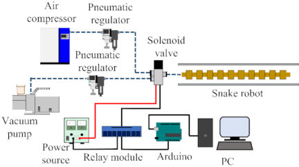
Fig. 20. Drive system for snake-shaped robot.
The motion of the snake robot was recorded using a video camera. The movement speed was measured while varying the driving frequency and applied pressure. For each driving frequency, pressures of 20, 25, and 30 kPa were applied. The negative pressure generated by the vacuum pump was set to \(-30\) kPa for all conditions. An acrylic pipe with an inner diameter of 50 mm was used as the pipeline for the measurements.
The relationship between the driving frequency and movement speed is shown in Fig. 21. For each driving frequency, the robot was actuated for 2–20 cycles, depending on the frequency condition. The locomotion test was repeated five times, and the average of the measured results was plotted. The maximum movement speed was 1.38 mm/s at an applied pressure of 30 kPa and a driving frequency of 0.139 Hz. A peak was observed in the locomotion speed, which is considered to be attributable to the dynamic response of the actuator. As described in Section 2.5, the average time constant of the actuator was 0.325 s. In the snake robot, three actuators were connected in series to reduce the number of pneumatic tubes. Assuming that the response delay accumulates along the three actuators, the characteristic response time of the third actuator is calculated to be 0.975 s (\({0.325 \times 3}\)). Since the robot is driven using six pneumatic input patterns, the corresponding cycle period is calculated to be 5.85 s (\({0.975 \times 6}\)), which corresponds to a driving frequency of 0.171 Hz. This calculated frequency is consistent with the experimentally observed response limit of 0.139 Hz, suggesting that the robot speed is limited by the dynamic response of the pneumatic actuator system.
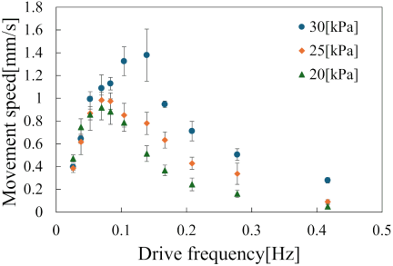
Fig. 21. Relationship between drive frequency and movement speed.
3.3. Evaluation of the Traction Force of the Snake Robot
The traction force of the snake robot was measured by varying the applied pressure and driving frequency. The experimental setup for traction force measurement is shown in Fig. 22. The snake robot and a load cell were connected by a string, and the robot was actuated for three cycles inside a pipe with an inner diameter of 50 mm. The maximum traction force was measured three times, and the average value was calculated. The measurement process is shown in Fig. 23.
The relationship between the driving frequency and maximum traction force is shown in Fig. 24. The traction force tended to increase as the driving frequency decreased. The maximum traction force was 14.57 mN at an applied pressure of 30 kPa and a driving frequency of 0.026 Hz. On the other hand, a lower driving frequency is expected to further increase the traction force.
To evaluate the limiting case under static conditions, the traction force was also measured without cyclic actuation, and a static traction force of 29.81 mN was obtained.
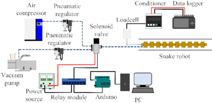
Fig. 22. Experimental configuration for traction force measurement.
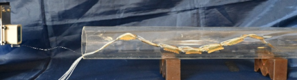
Fig. 23. Photograph of the traction force measurement experiment.
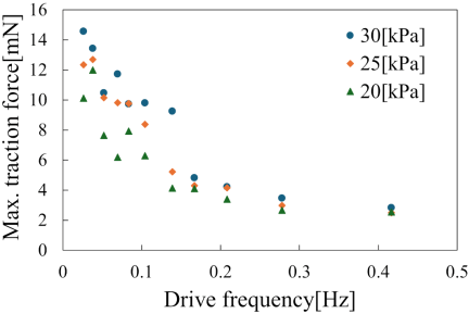
Fig. 24. Relationship between driving frequency and maximum traction force.
4. Conclusions
In this study, a film actuator capable of bidirectional bending under pneumatic pressure was fabricated by welding three PI films. A snake robot was also developed. The fabricated snake robot achieved a maximum movement speed and traction force of 1.38 mm/s and 14.57 mN, respectively.
Because the robot is composed of flexible materials, it has the advantage of enabling safe inspection without damaging the pipeline due to contact with the robot body. In addition, the robot is extremely lightweight, allowing a large number of units to be transported easily. This significantly reduces the labor associated with transportation at inspection sites and makes it possible to inspect a larger number of facilities from multiple perspectives and multiple points.
In future work, cameras and various sensors will be installed to observe the inside of the pipeline to measure the temperature and detect gas. By acquiring environmental data inside the pipeline, inspection accuracy is expected to greatly improve. If this robot is put into practical use, it will enable safe and nondestructive inspection of aging pipelines. It is also expected to contribute to the prevention of leakage and rupture accidents through the early detection of pipeline abnormalities.
- [1] H. Jang et al., “A review: Technological trends and development direction of pipeline robot systems,” J. Intell. Robot. Syst., Vol.105, No.3, Article No.59, 2022. https://doi.org/10.1007/s10846-022-01669-2
- [2] M. R. A. Md Zin, K. S. M. Sahari, J. Md Saad, A. Anuar, and A. T. Zulkarnain, “Development of a low cost small sized in-pipe robot,” Procedia Eng., Vol.41, pp. 1469-1475, 2012. https://doi.org/10.1016/j.proeng.2012.07.337
- [3] A. A. Abd Eltwab and A. Sameh, “A modular, multi-sensor crawler robot for adaptive pipeline inspection: Design and experimental validation,” Sci. Rep., Vol.16, Article No.880, 2026. https://doi.org/10.1038/s41598-025-32719-y
- [4] A. Gunatilake, L. Piyathilaka, S. Kodagoda, S. Barclay, and D. Vitanage, “Real-time 3D profiling with RGB-D mapping in pipelines using stereo camera vision and structured IR laser ring,” 14th IEEE Conf. Ind. Electron. Appl., pp. 916-921, 2019. https://doi.org/10.1109/ICIEA.2019.8834089
- [5] R. S. Elankavi, D. Dinakaran, R. M. K. Chetty, M. M. Ramya, and D. G. H. Samuel, “A review on wheeled type in-pipe inspection robot,” Int. J. Mech. Eng. Robot. Res., Vol.11, No.10, pp. 745-754, 2022. https://doi.org/10.18178/ijmerr.11.10.745-754
- [6] J. Park, D. Hyun, W.-H. Cho, T.-H. Kim, and H.-S. Yang, “Normal-force control for an in-pipe robot according to the inclination of pipelines,” IEEE Trans. Ind. Electron., Vol.58, No.12, pp. 5304-5310, 2011. https://doi.org/10.1109/TIE.2010.2095392
- [7] L. Xu, L. Zhang, J. Zhao, and K. Kim, “Cornering algorithm for a crawler in-pipe inspection robot,” Symmetry, Vol.12, No.12, Article No.2016, 2020. https://doi.org/10.3390/sym12122016
- [8] J. Park and H. Yang, “Pipeline mapping with crawler-type in-pipe robot feature,” J. Mech. Sci. Technol., Vol.37, No.10, pp. 5015-5020, 2023. https://doi.org/10.1007/s12206-023-0908-5
- [9] T. Ren, Q. Liu, Y. Li, and Y. Chen, “Design, analysis and innovation in variable radius active screw in-pipe drive mechanisms,” Int. J. Adv. Robot. Syst., Vol.14, No.3, 2017. https://doi.org/10.1177/1729881417703564
- [10] T. Li et al., “Development of an in-pipe robot with differential screw angles for curved pipes and vertical straight pipes,” J. Mech. Robot., Vol.9, No.5, Article No.051014, 2017. https://doi.org/10.1115/1.4037617
- [11] P. Li, S. Ma, C. Lyu, X. Jiang, and Y. Liu, “Energy-efficient control of a screw-drive pipe robot with consideration of actuator’s characteristics,” Robot. Biomim., Vol.3, Article No.11, 2016. https://doi.org/10.1186/s40638-016-0045-z
- [12] J. Qiao, J. Shang, and A. Goldenberg, “Development of inchworm in-pipe robot based on self-locking mechanism,” IEEE/ASME Trans. Mechatron., Vol.18, No.2, pp. 799-806, 2013. https://doi.org/10.1109/TMECH.2012.2184294
- [13] Q. Xie, S. Liu, and X. Ma, “Design of a novel inchworm in-pipe robot based on cam-linkage mechanism,” Adv. Mech. Eng., Vol.13, No.9, 2021. https://doi.org/10.1177/16878140211045193
- [14] J. Lim et al., “One pneumatic line based inchworm-like micro robot for half-inch pipe inspection,” Mechatronics, Vol.18, No.7, pp. 315-322, 2008. https://doi.org/10.1016/j.mechatronics.2008.05.007
- [15] S. Wakimoto, J. Nakajima, M. Tanaka, T. Kanda, and K. Suzumori, “A micro snake-like robot for small pipe inspection,” Proc. 2003 Int. Symp. Micromechatronics Hum. Sci., pp. 303-308, 2003. https://doi.org/10.1109/MHS.2003.1249959
- [16] F. Trebuňa, I. Virgala, M. Pástor, T. Lipták, and Ľ. Miková, “An inspection of pipe by snake robot,” Int. J. Adv. Robot. Syst., Vol.13, No.5, 2016. https://doi.org/10.1177/1729881416663668
- [17] C.-W. Huang, C.-H. Huang, Y.-H. Hung, and C.-Y. Chang, “Sensing pipes of a nuclear power mechanism using low-cost snake robot,” Adv. Mech. Eng., Vol.10, No.6, 2018. https://doi.org/10.1177/1687814018781286
- [18] I. Virgala et al., “Investigation of snake robot locomotion possibilities in a pipe,” Symmetry, Vol.12, No.6, Article No.939, 2020. https://doi.org/10.3390/sym12060939
- [19] S. A. Fjerdingen, P. Liljebäck, and A. A. Transeth, “A snake-like robot for internal inspection of complex pipe structures (PIKo),” 2009 IEEE/RSJ Int. Conf. Intell. Robots Syst., pp. 5665-5671, 2009. https://doi.org/10.1109/IROS.2009.5354751
- [20] Y. Miyake, D. Yamaguchi, S. Wakimoto, and T. Kanda, “Fabrication of bidirectionally bending rigid differential actuator using polyimide films,” Proc. JFPS Fluid Power Syst. Conf., 2023 (in Japanese).
- [21] D. Yamaguchi et al., “Concept and prototype of soft actuator for liquid nitrogen temperature environments,” J. Robot. Mechatron., Vol.32, No.5, pp. 1019-1026, 2020. https://doi.org/10.20965/jrm.2020.p1019
- [22] S. Wakimoto, K. Suzumori, M. Tanaka, and J. Nakajima, “In-pipe inspection micro robot adaptable to changes in pipe diameter,” J. Robot. Mechatron., Vol.15, No.6, pp. 609-615, 2003. https://doi.org/10.20965/jrm.2003.p0609
- [23] S. Wakimoto, K. Suzumori, and T. Kanda, “A bio-mimetic amphibious soft cord robot,” Trans. Jpn. Soc. Mech. Eng. C, Vol.72, No.714, pp. 471-477, 2006 (in Japanese). https://doi.org/10.1299/kikaic.72.471
This article is published under a Creative Commons Attribution-NoDerivatives 4.0 Internationa License.