
Paper:
Fabrication of a Magnetically Driven Device for Evaluating Cellular Responses to Vibratory Stimulation
Tasuku Nakahara
 , Yuto Arimatsu, Koji Egami, and Kazuyuki Minami
Graduate School of Sciences and Technology for Innovation, Yamaguchi University
2-16-1 Tokiwadai, Ube, Yamaguchi 755-8611, Japan

Cells possess sensors to detect external mechanical stimuli, and the process of converting these cues into biochemical reactions is known as mechanotransduction. Various vibration devices have been developed to evaluate cellular responses under vibratory stimulation. However, few devices can apply vibratory stimulation to a localized area while maintaining a low contamination risk during long-term culture. To address this challenge, we propose a magnetically driven device capable of applying vibratory stimulation to cells in vitro to evaluate cell proliferation and differentiation induction. The device integrates a polydimethylsiloxane membrane equipped with a neodymium magnet and a ring structure into a standard lidded culture dish. By utilizing the magnetic repulsive force from an electromagnet, the membrane vibrates via non-contact actuation. The device maintains a semi-sealed environment, minimizing the risk of contamination and making it highly suitable for long-term cultivation. Performance evaluations confirmed that membrane acceleration increased with the applied voltage. When vibratory stimulation with an acceleration of 0.1 G or higher was applied to cultured cells, the stimulated group exhibited a cell proliferation rate approximately 1.4 times greater than that of the non-stimulated group. Furthermore, culturing osteoblast-like cells in a differentiation-inducing medium resulted in widespread positive staining for alkaline phosphatase, confirming that the device environment supports osteogenic differentiation. Notably, no contamination or cell detachment occurred during a 72 h culture period. These results suggest that the proposed device is a potentially useful tool for evaluating cellular mechanotransduction under vibratory stimulation.
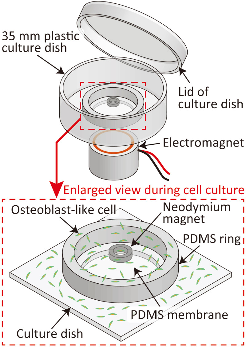
Magnetic cell-vibration device
1. Introduction
Cells possess sensors that detect external mechanical stimuli and alter their activity in response to these stimuli 1,2,3. Mechanotransduction is a cellular process that converts such mechanical stimuli into biochemical reactions 4. Among various stimuli, vibratory stimulation plays an important role in cell proliferation and differentiation. For example, applying mechanical vibration with appropriate frequencies and accelerations to osteoblasts has been reported to promote bone regeneration and osteogenic differentiation 5,6,7,8. Elucidating the function of mechanotransduction is crucial for investigating the mechanisms of homeostasis, developing treatments for diseases such as osteoporosis, and advancing regenerative medicine. Therefore, numerous studies have been conducted on this aspect to date.
Various vibration devices and systems have been developed to evaluate cellular mechanotransduction in response to vibratory stimulation in vitro. As a common method, systems in which an entire incubator or a multi-well plate is fixed to a large vibration generator driven by a motor or a piezoelectric element are widely used 9,10,11,12,13,14,15,16. In addition, miniaturized vibration and dynamic stimulation devices fabricated using microelectromechanical systems (MEMS) technology have been reported, which have been used to evaluate cellular responses to stimuli in detail during in situ observations under a microscope 17.
Although cellular characteristics in response to vibratory stimulation have been evaluated in several studies, few devices can apply this stimulation to a localized area while maintaining device convenience and a low risk of contamination. This is particularly important for experiments requiring long-term cultivation and observation over several days to weeks, such as those involving the proliferation and differentiation induction of osteoblasts. In conventional systems that use external vibration generators, the large size occupies a significant space within an incubator, and because they vibrate the entire culture dish, applying vibration to a localized area is difficult. It is also challenging to accurately control the frequency and amplitude of the vibrations applied to the cells. Furthermore, devices that operate with the culture chamber in an open state pose a risk of contamination, and they are therefore considered unsuitable for long-term culture experiments. For time-lapse observations and safe, long-term cultivation in applications such as drug screening, a device capable of applying vibration in a non-contact manner while maintaining a semi-sealed environment is warranted.
In this study, we propose a magnetically driven cell vibration device capable of applying vibratory stimulation to cells in vitro and confirming the induction of differentiation. The proposed device primarily consists of a polydimethylsiloxane (PDMS) membrane equipped with a neodymium magnet, a PDMS ring structure, and a standard cell culture dish. By utilizing the magnetic repulsive force generated by the magnetic field of a small electromagnet, the membrane can be vibrated through non-contact actuation. In addition, the vibratory stimulation (acceleration) applied to the cells adhering to the PDMS membrane can be easily controlled by varying the voltage applied to the electromagnet. Because the proposed device is incorporated into a cell culture dish with a lid, the risk of contamination is low, rendering it suitable for long-term culture experiments. The primary novelty of the proposed device lies in its structural and operational advantages over existing platforms. Unlike large, whole-plate external shakers that occupy considerable incubator space and lack localized control, our device achieves non-contact, localized actuation within a standard culture dish using a magnetic repulsive mechanism. Furthermore, compared with typical MEMS-based devices that involve complex and high-cost fabrication, our PDMS-based design offers a simple and cost-effective fabrication process. These characteristics successfully facilitate both microscopic imaging and quantitative evaluation, including cell proliferation and differentiation assays. This paper describes the device design, working principles, fabrication method, and actuation characteristics, including resonance characteristics. We also report the findings of the cell proliferation rate and induction of osteogenic differentiation through alkaline phosphatase (ALP) staining after vibratory stimulation experiments on osteoblast-like cells using the proposed device.
2. Materials and Methods
2.1. Device Design and Working Principle
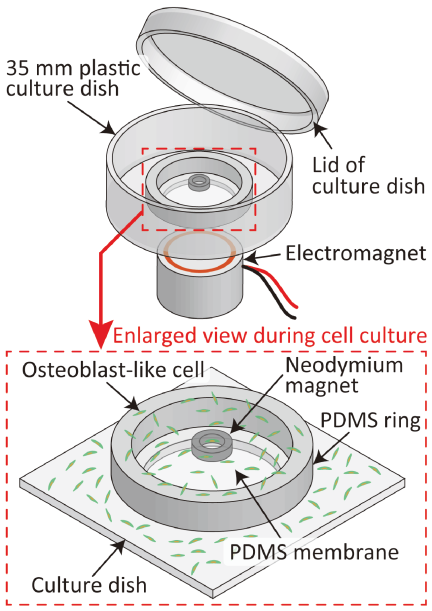
Fig. 1. Conceptual diagram of the proposed magnetically actuated cell-vibration device.
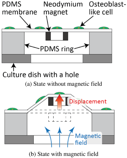
Fig. 2. Principle diagram of actuation in the proposed device in cross-section view.
Figure 1 shows a conceptual diagram of the proposed magnetically driven vibration device. The proposed device consists of a PDMS membrane, PDMS ring, ring-shaped neodymium magnet, and plastic culture dish with a hole. A 120-μm-thick PDMS membrane is used for cell vibration, and a PDMS ring (outer diameter: 22 mm, inner diameter: 16 mm, height: 2 mm) supports the PDMS membrane. A ring-shaped neodymium magnet (\(\Phi 4\times \Phi 2.5 \times 1.5\) mm) is used as a driving element to vibrate the PDMS membrane. The bottom surface of the PDMS ring is bonded to the culture dish, and the neodymium magnet is bonded to the back of the PDMS membrane. Because metal ions released from magnetic materials tend to be cytotoxic 18, the proposed device was designed to prevent the magnet from being submerged in the culture medium, thereby avoiding cytotoxicity (i.e., poor cell adhesion). Fig. 2 shows the driving principle (cross-sectional view) of the proposed device. A small electromagnet is placed under the device. An alternating magnetic field with an offset generated by the electromagnet vertically displaces the neodymium magnet. Combined with gravity and the restoring force of the PDMS pulling it back to its original position, this mechanism enables the PDMS membrane to vibrate in a non-contact manner. Among the cells adhering to the PDMS membrane, a uniform vibratory stimulation is applied to those located within the inner area of the ring-shaped neodymium magnet. Previous studies have reported that vibratory stimulation at approximately 50 Hz with an acceleration amplitude of 0.5 G increases cell proliferation capacity 9,12. Therefore, by applying similar vibratory stimuli to cells using this device, we expected that their responses would be evaluated. Because the target area for cell observation was enclosed within the small inner region of the rigid neodymium magnet (inner diameter: 2.5 mm), the influence of membrane deflection was minimized, thereby ensuring relatively uniform stimulation within the evaluated region.
2.2. Fabrication Process
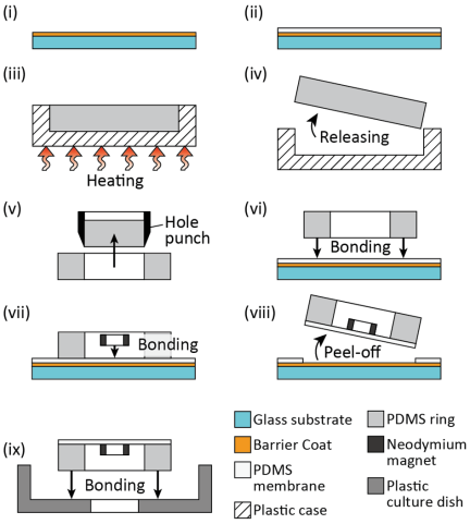
Fig. 3. Fabrication process of the proposed device: (i) spin-coating the Barrier Coat, (ii) forming the PDMS membrane, (iii) curing the PDMS solution for the ring, (iv) releasing the PDMS sheet, (v) punching the PDMS sheet to form the PDMS ring, (vi) bonding the PDMS ring to the PDMS membrane, (vii) bonding the magnet to the PDMS membrane, (viii) peeling off the assembled parts, and (ix) bonding the assembled parts to the plastic culture dish.
Figure 3 shows the fabrication process of the proposed device. The fabrication process consisted of fabrication of the PDMS membrane and PDMS ring, followed by the assembly process.
First, a glass substrate (\(22\times 22\times 0.17\)–0.25 mm, C022222, Matsunami Glass) was cleaned with a piranha solution. Then, Barrier Coat No. 7 (Shin-Etsu Chemical), an anti-adhesion agent for PDMS, was spin-coated onto the substrate. To form a 120-μm-thick PDMS membrane, a PDMS solution (SILPOT 184, DuPont Toray Specialty Materials) mixed at a base-to-curing agent ratio of \(10:1\) was spin-coated onto the substrate at 1000 rpm. After coating, the PDMS membrane was cured by baking at 75°C for 90 min using a hot plate (ND-1, AS ONE).
To fabricate the PDMS ring, a PDMS solution mixed at a base-to-curing agent ratio of \(10:1\) was poured into a plastic case (1-4698-01, AS ONE). Subsequently, the solution was degassed for 45 min to remove air bubbles. After the degassing process, the PDMS solution was cured by heating at 75°C for 90 min on a hot plate. After curing, the fabricated 2-mm-thick PDMS sheet was punched out using hole punches with diameters of 20 and 16 mm to fabricate a PDMS ring with an outer diameter of 20 mm, inner diameter of 16 mm, and thickness of 2 mm.
The PDMS membrane, PDMS ring, and ring-shaped neodymium magnet (NOR039, NeoMag; magnetic flux density: 243 mT; \(\Phi 4\times\Phi 2.5\times 1.5\) mm) were assembled. To enhance the bonding strength among the PDMS membrane, PDMS ring, and neodymium magnet, their surfaces were treated using a plasma modifier (PM100, Yamato Scientific) 19. These surface-treated parts were aligned such that their center positions roughly matched, and they were bonded together by baking on a hot plate at 120°C for 120 min. The magnetic flux of the neodymium magnet was perpendicular to its end face, and the magnet was placed such that the south pole side served as the bonding surface for the PDMS membrane. After the parts were bonded, the PDMS membrane was peeled off from the glass substrate. Finally, the assembled parts and a 35-mm-diameter plastic culture dish with a hole (hole diameter: 14 mm, D129300, Matsunami Glass) were bonded together using a silicone adhesive (KE-441, Shin-Etsu Chemical).
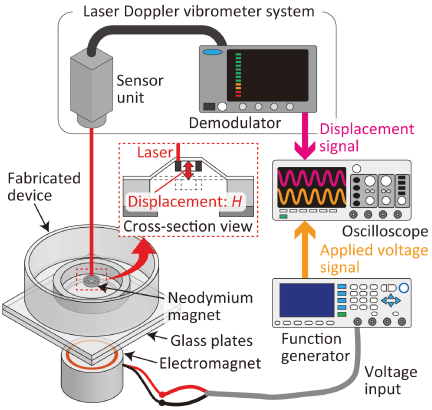
Fig. 4. Schematic diagram of the experimental setup for evaluating the displacement of the membrane.
2.3. Evaluation Method of Driving Characteristics of Device
To evaluate the driving characteristics of the device, the acceleration of the PDMS membrane was measured relative to the voltage applied to the electromagnet. Fig. 4 shows a schematic of the experimental setup used to evaluate the displacement of the membrane. To prevent magnetic attraction between the neodymium magnet of the device and the iron core of the electromagnet, and to achieve the desired driving displacement, two glass plates, each approximately 1.5 mm thick, were inserted between the electromagnet and the device. A 50 Hz sine wave generated by a multifunction generator (WF1974, NF Corporation) was applied to the electromagnet. The applied voltages were set to 0.2, 0.4, 0.6, 0.8, and 1.0 V, each with a 50% offset. The maximum acceleration \(a\) of the PDMS membrane was calculated from the displacement of the neodymium magnet bonded to the PDMS membrane using Eq. (1).
The change in acceleration with respect to frequency was evaluated to investigate the resonance frequency of the fabricated device. In this experiment, the voltage applied to the electromagnet was set to 1.0 V\(_{\textrm{p-p}}\) (with a 0.5 V offset). The displacement was measured using a laser Doppler vibrometer while increasing the frequency from 5 to 103 Hz in 2 Hz increments. The acceleration was then calculated from the measured displacement using Eq. (1).
2.4. Experimental Method for Cell Vibration Using the Fabricated Device
The mouse calvaria-derived osteoblast-like cell line MC3T3-E1 (RCB1126) used in this experiment was provided by RIKEN BRC through the National BioResource Project of MEXT, Japan. For the cellular vibratory stimulation experiment, the device was sterilized with 70% ethanol and washed with Dulbecco’s phosphate-buffered saline (D-PBS; 045-29795, FUJIFILM Wako Pure Chemical). To improve cell adhesion to the PDMS surface, D-PBS containing 1 μg/mL of laminin (23017015, Thermo Fisher Scientific) was introduced into the device to coat the surface. After the laminin solution was removed, the device was rinsed with D-PBS at room temperature. Finally, the osteoblast-like cells were seeded into the device at a concentration of \(1.0\times 10^4\) cells/mL. The above procedures were performed strictly in a clean bench to minimize the risk of contamination. Cells from passages 3 to 7 were used. The culture medium was MEM-\(\alpha\) (135-15175, FUJIFILM Wako Pure Chemical) containing 1 wt% penicillin-streptomycin (09367-34, Nacalai Tesque) as an antibiotic-antimycotic and 10 wt% fetal bovine serum (173012, Sigma-Aldrich). After culturing for 24 h in an incubator (MCO-20AIC, SANYO Electric), 1 h of vibratory stimulation was applied to the cells by subjecting the device to an alternating magnetic field inside the incubator. To ensure the application of vibratory stimulation with maximum accelerations of at least 0.1, 0.5, and 1.0 G, the voltage applied to the electromagnet was set as a 50 Hz sinusoidal wave at 0.2, 1.0, and 2.0 V\(_{\textrm{p-p}}\), respectively (with an offset equal to half of the set voltage). Following vibratory stimulation, cells within the inner region of the neodymium magnet were observed every 12 h under an inverted microscope (CKX41, Olympus) equipped with \(4\times\) and \(10\times\) objective lenses and a charge-coupled device (CCD) camera (DP72, Olympus). The number of cells was counted from \(4\times\) images using the multipoint tool in ImageJ (National Institutes of Health). As a control, a parallel experiment was conducted without vibratory stimulation. Three independent experiments were performed for each condition. Statistical analysis was conducted using one-way analysis of variance (ANOVA) followed by Dunnett’s test to compare the vibratory stimulation groups with the control group. A \(p\)-value of less than 0.05 was considered statistically significant. This analysis was performed using EZR (Jichi Medical University), a graphical user interface for R (R Foundation for Statistical Computing) 20.
2.5. Evaluation Method of Osteoblast Differentiation
Yashiro et al. confirmed that when osteoblast-like cells differentiate into osteoblasts, the expression of ALP, a marker enzyme for osteoblasts, increases 21. To confirm differentiation into osteoblasts on the fabricated device, cells were seeded into the device in the same manner as described in the previous section. After the cell culture reached confluence, the medium in the device was replaced with a differentiation-inducing medium (MEM-\(\alpha\) containing 1% penicillin-streptomycin, 10% fetal bovine serum, 10 mM \(\beta\)-glycerophosphate (50020, Sigma-Aldrich), and 50 μm ascorbic acid (A92902, Sigma-Aldrich)), and vibratory stimulation was applied for 1 h. Thereafter, the medium was changed every two days. Five days after vibratory stimulation, the cells were fixed using 3.7 wt% paraformaldehyde in D-PBS and permeabilized using a \(1:1\) (v/v) mixture of acetone and ethanol. The cells were stained for ALP using a staining kit (294-67001, FUJIFILM Wako Pure Chemical). After staining, the cells were observed using an inverted microscope equipped with a \(10\times\) objective lens and CCD camera. As a control, a parallel experiment was conducted using culture medium lacking differentiation-inducing reagents.
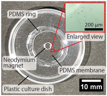
Fig. 5. Photograph of the fabricated device.
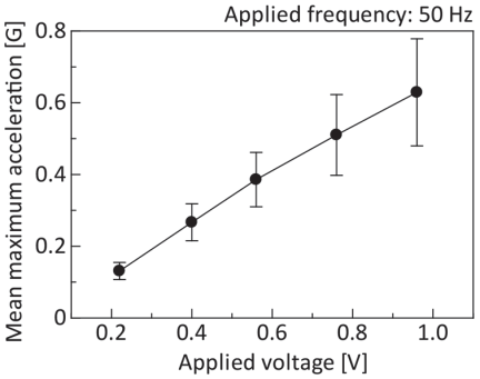
Fig. 6. Average maximum acceleration of the PDMS membrane for applied voltage to electromagnet.
3. Results and Discussion
3.1. Characteristics of the Fabricated Device
Figure 5 shows a photograph of the fabricated device. No magnet sinking or damage to the membrane was observed in the fabricated devices. Furthermore, on the surface of the PDMS membrane where cells adhere, there were no large foreign substances or scratches that would interfere with cell adhesion or observation. Therefore, the fabricated device was considered suitable for cell culture and cell vibratory stimulation experiments.
Figure 6 shows the relationship between the applied voltage and maximum acceleration. In this experiment, the actuation characteristics of seven devices were evaluated, and in all devices, the maximum acceleration increased with increasing applied voltage. The average maximum accelerations at applied voltages to the electromagnet of 0.22, 0.40, 0.56, 0.76, and 0.96 V were \(0.13{\pm}0.02\), \(0.27{\pm}0.05\), \(0.39{\pm}0.08\), \(0.51{\pm}0.11\), and \(0.63{\pm}0.15\) G, respectively. Fig. 7 shows the measurement results of the maximum acceleration relative to the applied frequency. The fabricated device reached a maximum value of 0.82 G at 43 Hz. Moreover, beyond 45 Hz, the acceleration decreased rapidly with an increase in the applied frequency. This sharp decline is characteristic of the device after it passes its resonance point. The acceleration at frequencies above 59 Hz was lower than the values recorded in the 5–41 Hz range, demonstrating that the performance in the higher-frequency range was inferior to that in the lower-frequency range. The variation in the standard deviation of the acceleration measurement relative to the applied voltage was attributed to the difference in the thickness of the PDMS membrane during device fabrication, which caused a change in the resonance frequency. Regarding the evaluation of the frequency response, the decrease in acceleration at frequencies above 59 Hz was attributed to the low responsiveness of the electromagnet, which resulted in a weakened magnetic field. However, because no detachment of the magnet or breakage of the membrane was observed during actuation, the fabricated device could be used for cell vibratory stimulation experiments. In this experiment, accelerations of at least 0.1 and 0.5 G were obtained by setting the applied voltages to 0.2 and 1.0 V\(_{\textrm{p-p}}\), respectively. Therefore, these voltage settings were appropriate for applying accelerations of 0.1 and 0.5 G in the cellular vibratory stimulation experiments. Furthermore, given that the maximum acceleration increased linearly with the applied voltage, 2.0 V\(_{\textrm{p-p}}\) was suitable for applying an acceleration greater than 1.0 G.
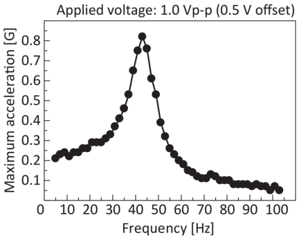
Fig. 7. Evaluation results of the frequency response of the device.
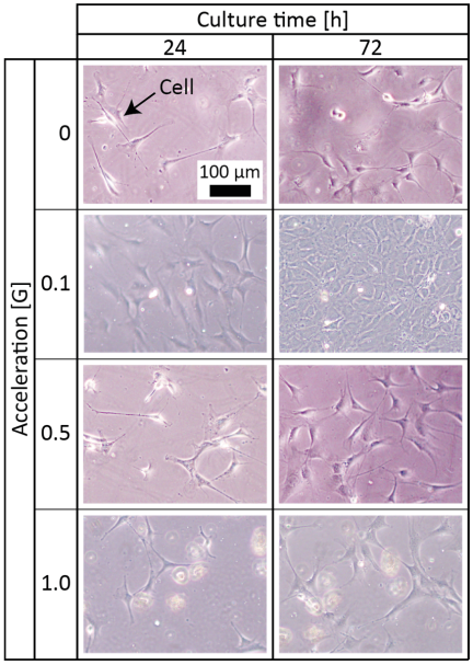
Fig. 8. Time-lapse observation results of the cells with or without vibratory stimulation. The enlarged images were captured using a \(10\times\) objective lens under each vibratory condition (control, 0.1 G, 0.5 G, and 1.0 G).
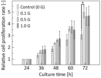
Fig. 9. Cell proliferation rate over culture time. The cell proliferation rate was normalized to the value at 24 h for each condition. Data are expressed as mean SD (\(N=3\)). *\(p<0.05\) compared to the control group (one-way ANOVA with Dunnett’s test).
3.2. Results of the Cell Vibratory Stimulation Experiment Using the Fabricated Device
Figure 8 shows enlarged images captured using a \(10\times\) objective lens under each vibratory condition (0, 0.1, 0.5, and 1.0 G) at 24 h, immediately prior to vibratory stimulation, and after 72 h of culture. The cells adhered to the PDMS membrane and proliferated as the culture progressed. In addition, the cells subjected to vibratory stimulation tended to show higher proliferation rates than those without vibratory stimulation. Fig. 9 shows the cell proliferation rate over culture time under each condition, where the number of cells immediately before vibratory stimulation (after 24 h of culture) was normalized to 1. As shown in the graph, after 72 h, the control and vibration (0.1 G) groups showed 3.1-fold and 5.0-fold increases, respectively, indicating a maximum difference in proliferation rate of approximately 1.6 times. The increase in proliferation rate due to vibratory stimulation was consistent with the results of Choi et al. 10. Therefore, the device fabricated in this experiment successfully applied vibratory stimulation to cells. Furthermore, because the 72 h culture was performed without any entry of foreign matter into the culture dish, cell contamination, or cell detachment, this device was considered highly suitable for cell culture. As shown in Fig. 9, a statistically significant increase in the cell proliferation rate was observed in the 0.1 G group compared to that in the control group (\(p<0.05\)). Although the 0.5 G and 1.0 G groups also demonstrated an increasing trend, these differences were not statistically significant (\(p>0.05\)). This could be attributed to the limited sample size (\(N=3\)). Further investigations with larger sample sizes are necessary to clarify the effects of higher vibratory stimulation on cell proliferation.
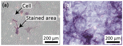
Fig. 10. Micrographs of cells stained for ALP cultured in the (a) absence and (b) presence of differentiation-inducing reagents at five days after vibration.
3.3. Evaluation Results of Osteoblast Differentiation
Figure 10 shows micrographs of cells stained for ALP, an osteoblast marker enzyme. Figs. 10(a) and (b) show cells cultured for five days after vibration in the absence and presence of the differentiation-inducing medium, respectively. When cultured in the absence of differentiation-inducing medium, the stained areas were limited to specific regions. In contrast, when cells were cultured in differentiation-inducing medium, stained areas were observed over a wide area. Because positive ALP staining was confirmed and the results showed a similar tendency to those in a study by Yashiro et al. 21, this device was considered applicable as a platform for differentiation experiments of osteoblast-like cells. However, it should be noted that the primary focus of the differentiation assay in this study was to verify that the long-term dynamic driving environment of the proposed device does not interfere with the inherent differentiation capability of the cells. Although the observed osteogenic differentiation was largely driven by the differentiation-inducing medium, these results successfully demonstrated the biological compatibility of the device. A rigorous comparison between the vibratory and non-vibratory conditions under identical differentiation settings is required in future studies to isolate and evaluate the specific effects of vibratory stimulation on the differentiation process.
On the basis of the experimental results of cell vibratory stimulation, the proposed device was found to have potential as a reliable experimental platform for investigating the mechanisms of cellular mechanotransduction, specifically regarding mechanosensitive sensors and intracellular information transmission. Cells sense external mechanical cues through specialized molecular sensors, such as mechanosensitive ion channels (e.g., Piezo1/2), integrins, and the cytoskeleton 22,23,24. These physical stimuli are subsequently converted into biochemical signals and transmitted into the nucleus via intracellular signaling cascades (e.g., calcium signaling or MAPK/ERK pathways) 25,26, ultimately triggering the downstream osteogenic differentiation observed in this study. Because our PDMS-based device achieves non-contact, controlled local vibration within a semi-sealed, standard culture dish, it can provide a highly stable and sterile mechanical microenvironment. This enables researchers to securely stimulate cells over extended periods and subsequently analyze the dynamics of these mechanosensitive molecular pathways without the risk of contamination. Consequently, this system can contribute to the understanding of intracellular sensing and information transmission in cells and tissues under defined vibrational conditions.
4. Conclusion
In this study, we developed a magnetically driven device capable of applying vibratory stimulation to cells in vitro to evaluate the induction of cell proliferation and differentiation. By combining non-contact actuation with a lidded structure, we achieved long-term culture with a minimized risk of contamination. The evaluation of the driving characteristics confirmed that the membrane acceleration increased with increasing applied voltage. Moreover, using this device, we confirmed that vibratory stimulation promoted cell proliferation and verified the induction of osteogenic differentiation via ALP staining. The successful maintenance of a stable culture environment for 72 h demonstrates the high practicality of the device. These results suggest that the proposed device is a useful tool for elucidating cellular mechanotransduction under vibratory stimulation.
Acknowledgments
This study was partially supported by JSPS KAKENHI (Grant Nos. JP22K18782 and JP26K00915), and JKA through promotional funds from the KEIRIN RACE.
- [1] F. Boccafoschi, M. Bosetti et al., “Dynamic fibroblast cultures: Response to mechanical stretching,” Cell Adhesion & Migration, Vol.1, No.3, pp. 124-128, 2007. https://doi.org/10.4161/cam.1.3.5144
- [2] K. Sato, T. Nakahara, and K. Minami, “Difference in the osteoblastic calcium signaling response between compression and stretching mechanical stimuli,” J. Robot. Mechatron., Vol.35, No.5, pp. 1135-1142, 2023. https://doi.org/10.20965/jrm.2023.p1135
- [3] T. Nakahara, S. Ono, and K. Minami, “Fabrication of a magnetically driven cell-stretching device for predefined cell alignment in vitro,” J. Robot. Mechatron., Vol.35, No.5, pp. 1143-1150, 2023. https://doi.org/10.20965/jrm.2023.p1143
- [4] S. Giulitti, A. Zambon et al., “Mechanotransduction through substrates engineering and microfluidic devices,” Current Opinion in Chemical Engineering, Vol.11, pp. 67-76, 2016. https://doi.org/10.1016/j.coche.2016.01.010
- [5] H. Gao, M. Zhai et al., “Low-level mechanical vibration enhances osteoblastogenesis via a canonical Wnt signaling-associated mechanism,” Molecular Medicine Reports, Vol.16, No.1, pp. 317-324, 2017. https://doi.org/10.3892/mmr.2017.6608
- [6] K. Sato and D. Oomori, “Development of vibration mechanical stimuli loading device for live cell fluorescence microscopy,” J. of Biomechanical Science and Engineering, Vol.17, No.2, Article No.21-00294, 2022. https://doi.org/10.1299/jbse.21-00294
- [7] S. García-López, R. E. Villanueva et al., “Micro-vibrations at 30 Hz on bone cells cultivated in vitro produce soluble factors for osteoclast inhibition and osteoblast activity,” Archives of Oral Biology, Vol.110, Article No.104594, 2020. https://doi.org/10.1016/j.archoralbio.2019.104594
- [8] Z. Fu, X. Huang et al., “Protective effects of low-magnitude high-frequency vibration on high glucose-induced osteoblast dysfunction and bone loss in diabetic rats,” J. of Orthopaedic Surgery and Research, Vol.16, Article No.650, 2021. https://doi.org/10.1186/s13018-021-02803-w
- [9] T. Shikata, T. Shiraishi et al., “Effects of amplitude and frequency of mechanical vibration stimulation on cultured osteoblasts,” J. of System Design and Dynamics, Vol.2, No.1, pp. 382-388, 2008. https://doi.org/10.1299/jsdd.2.382
- [10] D. Choi, T. Ishii et al., “Vertical vibration of mouse osteoblasts promotes cellular differentiation and cell cycle progression and induces aging in vitro,” Biomedicines, Vol.11, No.2, Article No.444, 2023. https://doi.org/10.3390/biomedicines11020444
- [11] Q. Guo, Y. Fu et al., “Amplitude dependence in extracellular vesicle release from cultured myotubes under vibration stimulation,” Biochemical and Biophysical Research Communications, Vol.797, Article No.153218, 2026. https://doi.org/10.1016/j.bbrc.2025.153218
- [12] W. W. Hou, Z. L. Zhu et al., “Involvement of wnt activation in the micromechanical vibration-enhanced osteogenic response of osteoblasts,” J. of Orthopaedic Science, Vol.16, No.5, pp. 598-605, 2011. https://doi.org/10.1007/s00776-011-0124-5
- [13] A. Matsushita, T. A. Kudo et al., “Frequency-regulated repeated micro-vibration promotes osteoblast differentiation through BMP signaling in MC3T3-E1 cells,” Life, Vol.15, No.4, Article No.588, 2025. https://doi.org/10.3390/life15040588
- [14] K.-i. Konno, T. Kosawada et al., “Development of three-dimensional micro vibration stage and its application to control device for cell culture,” J. of Biomechanical Science and Engineering, Vol.3, No.1, pp. 38-49, 2008. https://doi.org/10.1299/jbse.3.38
- [15] Y. Yamada, G. Umegaki et al., “Development of cell culture microdevice actuated by piezoelectric thin films for delivering mechanical vibratory stimuli to cells,” J. of Physics: Conf. Series, Vol.352, Article No.012027, 2012. https://doi.org/10.1088/1742-6596/352/1/012027
- [16] S. Benjakul, S. Jitpukdeebodintra et al., “Effects of low magnitude high frequency mechanical vibration combined with compressive force on human periodontal ligament cells in vitro,” European J. of Orthodontics, Vol.40, No.4, pp. 356-363, 2018. https://doi.org/10.1093/ejo/cjx062
- [17] K. Minami, T. Nakahara, and K. Sato, “Evaluation of the basic designs of a micro device that provides vibrational stimulation to cells,” J. Robot. Mechatron., Vol.35, No.5, pp. 1151-1157, 2023. https://doi.org/10.20965/jrm.2023.p1151
- [18] C. C. Shih, S. J. Lin et al., “The cytotoxicity of corrosion products of nitinol stent wire on cultured smooth muscle cells,” J. of Biomedial Materials Research, Vol.52, No.2, pp. 395-403, 2000. https://doi.org/10.1002/1097-4636(200011)52:2<395::aid-jbm21>3.0.co;2-b
- [19] S. Bhattacharya, A. Datta et al., “Studies on surface wettability of poly(dimethyl) siloxane (PDMS) and glass under oxygen-plasma treatment and correlation with bond strength,” J. of Microelectromechanical Systems, Vol.14, No.3, pp. 590-597, 2005. https://doi.org/10.1109/jmems.2005.844746
- [20] Y. Kanda, “Investigation of the freely available easy-to-use software ‘EZR’ for medical statistics,” Bone Marrow Transplantation, Vol.48, pp. 452-458, 2013. https://doi.org/10.1038/bmt.2012.244
- [21] M. Yashiro, M. Ohya et al., “Active vitamin D and vitamin D analogs stimulate fibroblast growth factor 23 production in osteocyte-like cells via the vitamin D receptor,” J. of Pharmaceutical and Biomedical Analysis, Vol.182, Article No.113139, 2020. https://doi.org/10.1016/j.jpba.2020.113139
- [22] T. Zhou, B. Gao et al., “Piezo1/2 mediate mechanotransduction essential for bone formation through concerted activation of NFAT-YAP1--catenin,” Elife, Vol.9, Article No.e52779, 2020. https://doi.org/10.7554/elife.52779
- [23] M. Sun, G. Chi et al., “Extracellular matrix stiffness controls osteogenic differentiation of mesenchymal stem cells mediated by integrin 5,” Stem Cell Research & Therapy, Vol.9, Article No.52, 2018. https://doi.org/10.1186/s13287-018-0798-0
- [24] P. S. Mathieu and E. G. Loboa, “Cytoskeletal and focal adhesion influences on mesenchymal stem cell shape, mechanical properties, and differentiation down osteogenic, adipogenic, and chondrogenic pathways,” Tissue Engineering Part B: Reviews, Vol.18, No.6, pp. 436-444, 2012. https://doi.org/10.1089/ten.teb.2012.0014
- [25] A. M. C. Barradas, H. A. M. Fernandes et al., “A calcium-induced signaling cascade leading to osteogenic differentiation of human bone marrow-derived mesenchymal stromal cells,” Biomaterials, Vol.33, No.11, pp. 3205-3215, 2012. https://doi.org/10.1016/j.biomaterials.2012.01.020
- [26] J.-M. Kim, Y.-S. Yang et al., “Biphasic regulation of osteoblast development via the ERK MAPK–mtor pathway,” Elife, Vol.11, Article No.e78069, 2022. https://doi.org/10.7554/elife.78069
This article is published under a Creative Commons Attribution-NoDerivatives 4.0 Internationa License.