
Paper:
Convex Tape Based Telescopic Roof Snow Removal Robot for Life Support in Heavy Snowfall Regions
Kenya Kobayashi*, Sota Ochiai*, Kyohei Kuroki*, Mio Funami*, Daisuke Furukawa*, Takuya Arakawa**, Tsuyoshi Hironaka**, and Takashi Kei Saito*

*Akita Prefectural University
84-4 Aza Ebinokuchi, Tsuchiya, Yurihonjo, Akita 015-0055, Japan
**KYB Corporation
1-12-1 Asamizodai, Minami-ku, Sagamihara, Kanagawa 252-0328, Japan

The most common life-threatening issue in heavy snowfall regions is human casualties caused by snow damage, particularly accidents during snow-removal operations, such as roof snow clearing. This study aims to develop a telescopic convex tape expansion mechanism to prevent such accidents. We constructed and evaluated a prototype telescopic mechanism (Makijaku-Ude Type-Super K) featuring a reduced number of parts and eliminating springs. The results confirm its ability to withstand stronger snow loads during operation. The robot system, named Setsu-ichi, equipped with two Type-SK units, successfully completed snow-removal operations over a distance of approximately 7 meters.
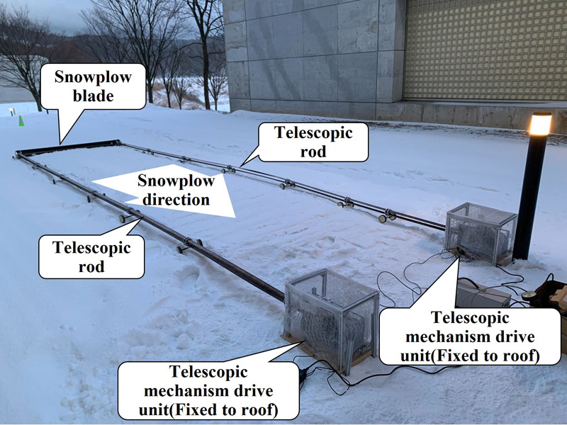
Telescopic roof snow removal robot
1. Introduction
1.1. Background and Objective of Study
Japan experiences significant challenges owing to heavy snowfall, with designated heavy snowfall zones comprising 50.8% of the national land area and special heavy snowfall zones representing 19.8% a. The population residing in these areas accounts for 14.5% and 2.2% of the national population, respectively. In recent years, climate change has intensified this problem, causing concentrated heavy snowfall and blizzards over short periods. These conditions lead to building collapse, infrastructure paralysis in transportation and communication systems, and numerous casualties during snow-removal operations. Snow-related casualties are a major concern in heavy snowfall regions. Despite the relatively light snowfall during the 2023 winter season, 22 deaths occurred owing to snow-related accidents. Snow-related fatalities have been increasing, significantly exceeding fatalities from other natural disasters such as wind and flood damage. Approximately 90% of snow-related deaths occur during snow-removal operations. Heavy snowfall regions experience more rapid population decline and aging than the national average, and this trend is particularly pronounced in special heavy snowfall zones. Among those who died during snow-removal work, approximately 90% were aged 65 years or older. The types of fatal accidents during snow removal include roof falls, snow falling from roofs, falling into drainage channels, ladder falls, and accidents involving snow-removal equipment, with roof falls being the most common.
Removing snow accumulation from roofs is a significant challenge worldwide, not limited to Japan. Consequently, methods such as installing hot water sprinkler systems on roofs have been employed 1. In recent years, measures to maintain the power-generation capacity of rooftop solar panels have advanced, including using the panels’ heat to melt snow or introducing microscopic water-repellent structures on their surfaces to prevent snow buildup 2. However, the energy consumption associated with snow melting remains a significant cost. Moreover, because water expands when melted snow freezes, there is a risk of damaging drainpipes. Moreover, applying specialized water-repellent treatments to the entire roof surface is difficult, and mechanical and autonomous snow-removal robots continue to undergo refinement 3. Snowplowing is a fundamentally difficult energy-consuming task, and robots with batteries are extremely heavy and risky for fall accidents. Another type of system is proposed to wipe out snow using movable frames fixed on roofs 4. It is effective at small scales, such as vehicle roof snow removal, but for houses, installing such large instruments that can cover roofs becomes expensive and should be completed before the snow season. It is difficult to decide on such an installation for candidate customers immediately before the season because snowfall changes randomly every year and is affected by climate change.
Considering these various snow-removal challenges, we defined the concept of our roof snow-removal robot in the following three stages. (a) A mechanical snow-removal system is preferable: compared with snow-melting systems, it consumes relatively less energy and avoids problems caused by the refreezing of melted snow. (b) A lightweight and compact telescopic mechanism is required: if the telescoping mechanism has a working range suitable for residential roofs, the snow-removal blade can be operated by connecting two such mechanisms in parallel at both ends of the blade. A compact mechanism allows installation on the roof with minimal effort, even in the middle of the snowfall season, provided that snow-removal work has already been performed. (c) Build an automated snow-removal system equipped with a telescopic mechanism, sensors, processor, weather data from a network, and power supply for autonomous operation: control software is essential to ensure the safety of homes where the system is installed. Weather data (such as weather forecasts including wind direction, wind speed, and snowfall amount) are also considered necessary.
Step (a) involves strategic selection of the automatic roof snow-removal concept. This is similar to a social survey, and the selected concept is suited to Japan’s climate, which features heavy and wet snowfall.
Step (b) involves a lightweight telescopic mechanism, several meters in length, that can be applied outdoors and used for practical operations. If realized, it would constitute an innovation in soft robotics and would be inherently academic in nature. We did not achieve this objective in our previous study.
Step (c) involves practical technical improvements based on the novel telescopic mechanism. One key improvement is the ability to install the system during the snowfall season, which is lacking in conventional automated snow-removal devices.
Based on our previous studies 5 on the convex telescopic manipulator (“Makijaku-Ude”) developed in our laboratory, we aim to construct a trial automated snowplow robot system for residential roof snow removal. This can be considered the first successful achievement of Step (b). We will proceed with this study toward practical applications as in Step (c) as our next step.
1.2. Overview of Convex-Based Telescopic Mechanism
The telescopic mechanism employed in this study was originally developed in our laboratory to expand robotic applications 6. Its major features include reversible bending under excessive loads, compact storage capability, and high extension ratio. Fig. 1 presents the basic configuration of the telescopic manipulator Type-Super K (Type-SK), the key device in this study. Boxed arrows indicate powered movements and dotted lines indicate passive movements. It functions as a convex tape measure using sliding guide plates or tape-binding rings to bundle multiple convex tapes, thereby reinforcing the tape-based telescoping structure. The plates and rings are sequentially connected to one another by wires extending from the tape drive unit to the tip of the telescoping section. Within the scope of this concept, variations in structure and tape-drive methods are conceivable. The most compact form, presented in Fig. 1, uses only a single folded convex tape as two bundled tapes. Elastic convex-shaped metal tape has been used as an extensible tape measure because of its linear elongation and compact winding properties 7. Subsequently, to enhance structural strength, it was formed into a quasi-rod shape rather than a convex shape or combined with other materials for applications such as telescopic antennas 8,9. An application example for industrial robot arms involves forming a quasi-rod shape by facing the concave surfaces of two tubular telescoping mechanisms toward each other, then attaching a bucket as the end effector. However, this was limited to light loads 10. Driving methods for such elastic tapes can be broadly classified into two types: driving by pinching the tape with a drive roller 11 and driving using a drive sprocket that meshes with holes punched in the tape 12. In addition to driving by pinching the tape with a power transmission roller 13, we employed a direct drive from a reel that fixes the tape ends to handle heavy loads 6. However, a direct reel drive requires the tape rewinding prevention mechanism described in the next section. The mechanism can function independently as a portable lifting device or remote manipulator without being integrated into robots or large machinery, and has applications such as high-altitude work platforms, safety lines, and simple lifts. The previously developed telescopic mechanism Type-K achieved output forces exceeding 300 N, with an extension range suitable for robotic manipulation 6. Type-K demonstrated successful application in a three-degree-of-freedom spatial parallel mechanism robot, validating the concept of multi-axis control systems. However, challenges remain in achieving a consistent performance across multiple units and maintaining stability under varying load conditions.
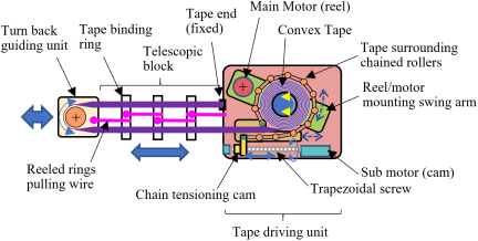
Fig. 1. Schematic view of a telescopic manipulator (Type-Super K folding type).
1.3. Progress of Type-Super K from Type-K, the Former Model Tape Unwinding Prevention Mechanism
Our telescopic mechanism experiences a phenomenon called “tape unwinding,” in which gaps form between layers of metal tape wound on the reel. This occurs because the metal tape, forced from its naturally curved state into a flat configuration when wound, exerts restoring forces attempting to return to the curved shape. When tape unwinding occurs, gaps between layers prevent smooth tape feeding during extension, particularly problematic during extension operations (Fig. 2). Part A, where the tape transitions from a trough shape to flat shape, and Part B, the narrow area on the opposite side where it is difficult to position the belt surrounding the reel, are particularly prone to unwinding. If the tape bulges outward, it creates a major obstacle to the tape feed drive; in the worst case, the reel rotation may stop. The original Type-K mechanism employed a smooth surface belt by polytetrafluoroethylene (PTFE) to press the tape layers together using nine springs, two sets of four springs for each rolled tape side, and one large spring to tighten the belt (Fig. 3(a)) to tension the belt for the unwinding prevention mechanism. However, the structure is complicated, and the adequate ranges of spring constants and working ranges of the employed springs are limited and unsuitable for applications over 4 m. Therefore, this study develops a mechanism using trapezoidal screws and motors that synchronize with reel rotation through an electronic cam control to maintain constant tension, replacing the springs with more durable mechanical solutions (Fig. 3(b)).
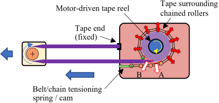
Fig. 2. Schematic view of tape unwinding probrem.
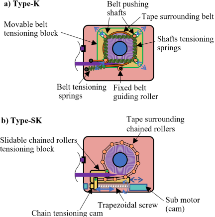
Fig. 3. Comparison of Type-K and SK.
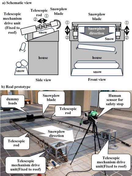
Fig. 4. Roof snow-removal robot system “Setsu-ichi 2023.”
1.4. Overview of Telescopic Snow Removal Robot “Setsu-ichi”
Developing snow-removal applications using telescopic mechanisms began in earnest in 2015. In 2016, two prototype machines equipped with snow-removal blades on a single telescopic unit were publicly demonstrated, subsequently designated as the “Setsu-ichi” series 14,15. All previous “Setsu-ichi” iterations assumed fixed installation on roofs, initially operating by extending the blade away from the drive unit to push snow away. However, this approach imposed significant loads on the tape restraint mechanism during extension, limiting output performance. Additionally, single-unit configurations experienced problems with blade-mechanism connection bending under uneven lateral loads on the blade. Therefore, the “Setsu-ichi 2023” system (Fig. 4) based its telescopic mechanism on the reliable original Type-K design, replacing the stepping motors (24 V drive, 3 A maximum current consumption), which were prone to step-out, with simple geared motors (6 V drive, 13 A maximum current consumption) 7. The convex tape installed in the Type-K (stainless spring steel extra-hard grade, custom order, R18, width 50 mm, thickness 0.2 mm, Sunco Spring Co., Ltd.) was changed from 4 to 17 m. As the Type-K mechanism uses a single-fold configuration, the telescopic operating range is half the installed length, expanding from 2 to 8.5 m. This length was designed to cover half of a typical residential roof. The total mass of the system was 21 kg, with a lower output designed for frequent snow removal before significant snow accumulation. Human sensors were integrated into the system to confirm that no people were present before snow-removal operations, and the sensor response stopped the robot to ensure safety. However, operational experiments revealed that the unwinding prevention mechanism springs (belt tensioning spring in Fig. 3(a)), which were not extended from the original 4 m convex specification, could not accommodate the increased winding length. The spring extension limit caused the system to stop after retracting approximately 4 m from the fully extended 8.5 m state. The most recent “Setsu-ichi 2024” system achieved full 17 m extension by replacing the unwinding prevention mechanism springs with rubber band 16. As described later, the outer circumference of the Type-K reel with wound tape changes more than 100 mm with 17 m tape installation in the full-length operation. It is an intermediate trial immediately before Type-SK development, and the lack of tension of the rubber band caused tape unwinding during the pushing of the snow-removal blade, as expected. This study reflects this effort and employs electronic cam for the tensioning of the chain, instead of a rubber band, targeting a stable extension from 0 to 7.5 m to advance toward practical implementation. This is Type-SK.
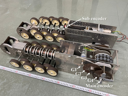
Fig. 5. Photograph of telescopic manipulators (Type-Super K folding type).
2. Development of Snow Removal Equipment
2.1. Type-Super K Telescopic Mechanism Overview
2.1.1. Basic Specifications
The improved Type-SK telescopic mechanism is a refinement of the previous Type-K model, with simplified unwinding prevention mechanism (Fig. 3). The basic structural components used aluminum alloy (A2017). Fig. 5 presents the Type-SK mechanism. Two units were fabricated: Unit 1 had gray plastic side panels, and Unit 2 had black panels. Table 1 lists the basic specifications of the Type-SK and former Type-K mechanism. The primary design parameters “reel diameter, convex thickness, and target length” are described later and are related to the setting of electronic cam. The reel and roller diameters at the tip of the fold were set to match the curvature of the convex tape when naturally bent into a U-shape. This is because depending on the physical properties of the convex material used, a curvature that is either too small or too large is expected to place undue stress on the component. The total mass of the system is approximately 30 kg, 9 kg higher than that of the former model; however, this is achieved by simply extending the inside metal tapes from 4 to 17 m.
Table 1. Basic specifications of Type-K and SK.
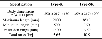
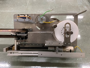
Fig. 6. Inside view of Type-SK.
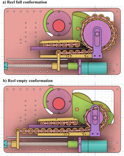
Fig. 7. Parts configuration drawings of Type-SK.
2.1.2. Internal Structure
The internal structure of the Type-SK mechanism incorporates a main motor (540 K75, TAMIYA) for reel drive and a sub-motor (540 K300, TAMIYA) for unwinding prevention mechanism control. Power from the main motor is transmitted through the gears on the body side to drive the reel. The sub-motor drives the trapezoidal screw for the unwinding prevention mechanism (Fig. 6). The metal tape travel path from the reel through the tape from the transition guiding unit must remain at a constant position relative to the guide to prevent unwinding. Therefore, the tape separation point from the reel must be maintained at a fixed location. However, as the reel radius varies with the amount of wound tape, the reel axis must move along the left-right axis relative to the body. This is accomplished by having the reel swing about the main motor axis, enabling left-right axis movement. The vertical displacement from this swinging motion is accommodated by a transition guiding unit moving on slide rails (SAR207, MISUMI) relative to the body. The swing operates passively by tightening the unwinding prevention mechanism chain. The tape from transition guiding unit moves passively by connecting it to the reel axis only in the vertical direction (Fig. 7). The unwinding prevention mechanism for this spring element-omitted structure employs an electronic cam according to the latest model, Type-M, for daily living support 17, and has been further improved for more stable operation.
2.1.3. Swing Arm Reduction Gear
The swing arm reduction gear system employs gears G1 and G3 with 20 teeth, and gears G2 and G4 with 100 teeth (Fig. 5). Gears G3 and G4 are mounted coaxially with identical gears on opposite faces to stabilize the reel rotation and swing motion. The reduction ratio from the main motor, including gear head reduction, is 1875. The swing-arm design for the reel axis drive anticipates the future implementation of a single-motor drive using a physical cam. Fixing the main motor to the body simplifies the power extraction.
2.1.4. Metal Tape Turn-Back Section
The metal tape folds back at the turn-back section (Fig. 8) with the end fixed to the body. During extension, the tape extends from the reel through the turn-back section toward the fixed end. Miniature bearings are installed at the turn-back section to minimize friction with the metal tape. The snow-removal blade attaches to this component.
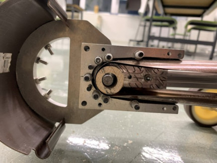
Fig. 8. Snow removal blade and metal tape turn-back section.
2.2. Unwinding Prevention Mechanism Development
Type-K mechanism tensions the belt surrounding the reel using metal springs or rubber. However, concerns about outdoor degradation and large hysteresis of these materials led to the development of an improved mechanism using a sub-motor and trapezoidal screw (MTSTR10-200, MISUMI) synchronized with the reel through electronic cam control to achieve more stable operation with reduced hysteresis.
2.2.1. Initial Design
The initial design fixed the unwinding prevention chain to a transition guide-reel axis fixture. However, this design failed to consider the reel-side guide (PTFE material) that prevents the tape from protruding outside the reel during unwinding, necessitating a revision of the fixed end attachment position. A large slide rail (SAR320, MISUMI) in the lower portion fixes from the body to a wide block nut (MTSBHR10, MISUMI) for the trapezoidal screw. This prevents the rotation of the block nut when converting screw rotation to linear motion. The unwinding prevention chain primarily uses a double-speed chain (WCHE3-18, MISUMI); however, when the reel radius is maximum, this chain interferes with the swing arm reduction gear shaft. Therefore, custom chain segments using miniature bearings (Micro Precision (ISC) 623-H-ZZ, NSK) are connected to the double-speed chain.
2.2.2. Early Designs
Early designs relocated the fixed end of the unwinding prevention chain to the transition guide-side panel. However, unwinding was not eliminated. The cause was determined to be insufficient tightening of the narrow space between the reel and separating tape.
2.2.3. Later Design
The later design revised the chain-fixing position on the transition guide side panel to enable tightening, even in the narrow space between the reel and tape. However, unwinding was not completely eliminated. The early design experienced component deformation when large tension was applied to the chain, but increased rigidity and modified attachment methods in the late design enabled the application of greater tension. Additionally, the sub-motor was changed from a servo motor (KRS-9304HV ICS, Kondo Kagaku) to an inexpensive geared motor (540K300, Tamiya) owing to the control method considerations and cost.
2.3. Metal Tape Transition Guide Development
As the convex metal tape feeds from the reel, the tape cross-section transitions from straight when wound on the reel to curved. This region is termed the metal tape transition section. During compression loading, the tape path curves and deviates, preventing normal telescopic operation. To solve this, guides are placed above and below the metal tape to physically prevent tape path deviation. Additionally, to avoid resistance to reel rotation and extension, rollers are used in the guides to reduce friction. The transition guide rollers use a double-speed chain for the lower surface with an independent double-speed chain fixed on the upper surface. Grooves are machined into the bottom and top guide parts, with the main rollers of the double-speed chain falling into these grooves and the bushings on both sides of the main rollers resting on the groove edges. This allows the main rollers to rotate freely while maintaining an ideal chain shape. The initial design had a poor clearance for the rollers near the reel, creating significant resistance to reel rotation and extension. The later design achieved a smooth drive by offsetting the upper roller and guide parts on the reel side upward by 5 mm.
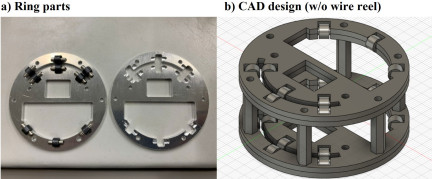
Fig. 9. Tape binding ring parts design.
2.4. Binding Ring Development
When extending 7.75 m of metal tape from the reel, the tape lacks directionality and experiences twisting and bending, causing dispersion that prevents linear extension. Therefore, rings (binding rings) constrain the tape before and after folding at approximately 1.2 m intervals to prevent twisting and bending, enabling linear telescopic motion. The ring uses aluminum construction with cylindrical resin bearings (Iglidur bushings, Igus) at contact points with the metal tape for low friction (Fig. 9), and metal wire reels extending to 1.2 m (Key Holder Reel Type 53124086, MonotaRO). The rings minimize the total length during maximum contraction, achieving a 7.75 m extension with six nodes and seven reels and a minimum contracted total length of 760 mm, including the main body. This design solves all previously encountered problems. Additionally, the tire parts (439E-UR7, Hammer Caster) were attached to the binding rings and turn-back section, enabling extension parallel to the operating surface on level ground or roofs (Fig. 10).
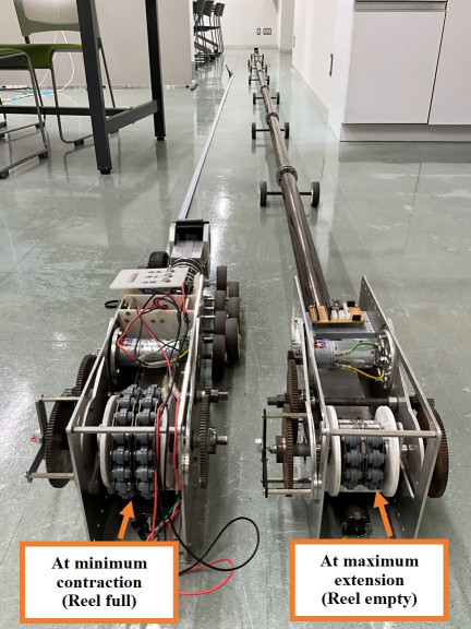
Fig. 10. Angled view of manipulators.
2.5. Anti-Slip Coating
To achieve a completely unwinding-free precision drive in the Type-SK, previous efforts focused on low-friction tightening using unwinding prevention mechanism rollers against the reel axis drive. However, a certain level of friction inevitably occurred, causing unwinding as the wound tape layers slipped against each other. Therefore, an outdoor anti-slip spray (Anti-slip, RUST-OLEUM) was applied to the metal tape to increase tape friction and prevent unwinding, together with the unwinding prevention mechanism. Unwinding occurred despite the anti-slip spray application, and completely unwinding-free precision drive was not achieved. However, clear differences in the feed speed and unwinding occurrence were observed before and after spray application. Before application, 60 seconds of extension required approximately 20 or more seconds of contraction operation, whereas after application only approximately 10 seconds of contraction were needed to complete the re-tightening for 60 seconds of extension. Anti-slip spray durability remains unverified, although problem-free operation was achieved after approximately 10 extension cycles over approximately 2 months of testing, despite gradual coating removal during the operation. Anti-slip coating application effectively and significantly reduced the extension time. The layer added ca. 0.12 mm on the outer side of the tape by the anti-slip coating, increasing the reel radius at minimum contraction, significantly affecting the electronic cam ratio.
2.6. Electrical System
2.6.1. Electronic Cam
The sub-motor operates synchronously with reel rotation through electronic cam control. The electronic cam system uses a main magnetic rotary encoder (AS5600) to read the reel axis rotation angle, with a small control board (Arduino Uno Revision 3, Arduino LLC) calculating the target rotation angle for the sub rotary encoder (AS5600) and switching current to the sub geared motor on and off. The ideal outer circumference of the wound tape on the reel during telescopic motion is expressed as a linear function in Eq. (1):
| \(u\) : | Outer circumference length |
| \(h\) : | Metal tape thickness (0.2 mm for Type-SK) |
| \(x\) : | Reel rotation number |
| \(d\) : | Reel axis diameter (50 mm for Type-SK) |
Therefore, the metal tape outer circumference length changes by \(2h\pi\) per reel rotation, requiring the trapezoidal screw where the unwinding prevention chain connects to move accordingly. The pitch of the trapezoidal screw used is 2 mm, therefore, moving the unwinding prevention chain by \(2h\pi\) requires rotating the trapezoidal screw by \(h\pi\) times. The metal tape thickness \(h\) before anti-slip coating application was 0.2 mm, hence, the ideal reel-to-trapezoidal screw rotation ratio (electronic cam ratio) in this state is approximately 0.628. However, the electronic cam ratio during the actual operation is approximately 0.9. This is owing to the increase in the thickness of the metal tape caused by applying an approximately 0.12 mm anti-slip coating, microscopic gaps between wound tape layers on the reel, and effects of minute unwinding. As the detailed values related to 17 m tape operation, reel rotation number becomes 0 to 82, with the ideal length of the tape extension becoming over 17 m, 17159.6 mm, and the outer circumference length 157.1 (0 rotation) to 260.1 (82 rotations). The difference, which indicates the edge position shift of the chained rollers, is 103 mm. The unwinding preventing mechanism should cover this position shift without causing unwinding.
2.6.2. Wiring
The electrical system receives power per unit from a commercial 100 V AC through a 12 V 5 A AC adapter (65 W class-switching AC adapter ATS065T-P120, Akizuki Denshi). Control uses Arduino Uno Revision 3 with two motor drivers IBT-4 (Hilitand), two rotary encoders, and switches for extension, stop, and contraction commands. Connecting switch wiring to another unit’s Arduino enables a synchronized drive (Fig. 11). Limit switches can be implemented in the unwinding prevention mechanism to prevent tape crushing from excessive contraction and tape bending from excessive extension, although time constraints prevented implementation in this study.
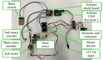
Fig. 11. Wiring photograph.
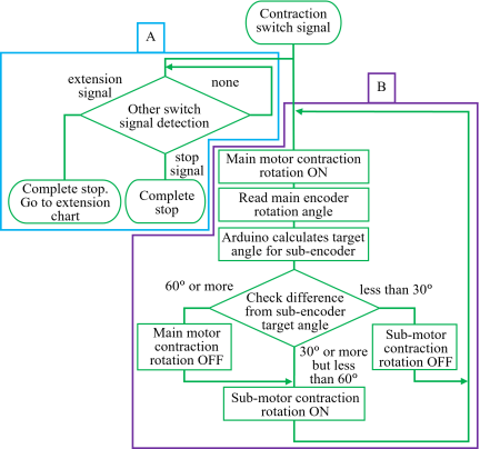
Fig. 12. Contraction flowchart.
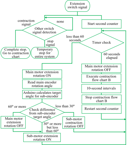
Fig. 13. Extension flowchart.
2.6.3. Software
The Type-SK program is constructed according to flowcharts for contraction and extension operations (Figs. 12 and 13). The program executes on Arduino Uno Revision 3, implementing electronic cam control, motor speed regulation, and safety interlocks.
3. Performance Evaluation
3.1. Extension Operation Overview
The trapezoidal screw of the unwinding prevention mechanism synchronizes with the reel through an electronic cam control. Initially, the Type-SK aimed for precision drive with no unwinding through the unwinding prevention mechanism. During contraction from maximum to minimum with anti-slip coating applied, an electronic cam ratio of 0.85 achieved problem-free operation, requiring approximately 33 minutes. However, during extension, the unwinding prevention mechanism could not completely prevent unwinding, irrespective of chain tension adjustment. Specifically, at low tension, tape fed out while unwinding, and at maximum extension, the tape bent at the axis-fixing point, causing breakage. With high tension, gradual unwinding increased the reel radius beyond ideal values, exceeding the sub-motor allowable torque and causing motor stoppage. This phenomenon occurred earlier with greater tension. Therefore, precision drive was abandoned to permit certain unwinding. Specifically, moderate tension that was neither too large nor too small prevented bending while extending the margin before exceeding sub-motor allowable torque. The extension operation method changed from constant speed rotation to repeated cycles of [60 seconds extension \(\rightarrow\) 10 seconds contraction \(\rightarrow\) 60 seconds extension \(\rightarrow\) 10 seconds contraction \(\rightarrow\) …], with the 10-second contraction period re-tightening the unwinding (Fig. 14). This achieved manual operation from minimum to maximum extension without stoppage or tape bending. The electronic cam rotation ratio between the reel and trapezoidal screw was 0.85, the same as that during contraction, requiring approximately 45 minutes. The calculated approximate extension equations for Units 1 and 2 from Fig. 14 are as follows:
| \(y\) : | Extension length [mm] |
| \(x\) : | Time [minute] |
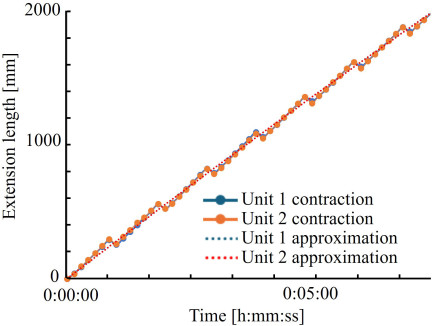
Fig. 14. Extension length measurement results (partial).
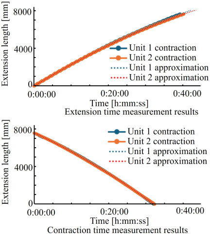
Fig. 15. Extension/contraction length measurement results.
3.2. Extension and Contraction Time Measurement
3.2.1. Measurement Overview
This section measures the amount of movement per unit time from maximum to minimum for both Type-SK Units 1 and 2, evaluating whether synchronized dual-unit operation for roof snow removal is possible by graphing the extension behavior. The experimental apparatus was assembled indoors. Paper was placed on the floor with marks indicating the turn-back section position every 10 seconds to measure the amount of movement. Extension and contraction were measured once each for Units 1 and 2, and the results were plotted graphically.
3.2.2. Results
Measurements were conducted indoors at 20°C temperature and 35% humidity. Extension time was 39 minutes 20 seconds for Unit 1 and 40 minutes 20 seconds for Unit 2. Contraction time was 32 minutes for Unit 1 and 32 minutes 20 seconds for Unit 2 (Fig. 15). Both extension and contraction indicated no significant speed differences between Units 1 and 2, indicating that synchronized operation for roof snow removal is possible using simple operation command signals (switches). The approximation curves fit the quadratic functions. The calculated approximate extension equations for Units 1 and 2 from Fig. 15 are as follows:
The calculated approximate contraction equations for Units 1 and 2 from Fig. 15 are as follows:
| \(y\) : | Extension length [mm] |
| \(x\) : | Time [minute] |
Table 2. Tensile and compression load measurement results.
3.3. Tensile and Compression Load Measurement
3.3.1. Measurement Overview
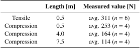
This section measures the tensile and compression loads of one Type-SK unit to evaluate roof snow-removal capability. For tensile load measurement, the turn-back section and spring scale (TDTB-50, TRUSCO) were fixed with a cable, with the Type-SK body and spring scale pulled apart manually. Measurements were taken at a 0.5 m extension. The Type-SK main unit was fixed to a wall to measure the compressive load along the extension axis. The tape turn-back section was connected to a fixed weight and spring scale via cables. This arrangement decomposed the compressive load \(F\) into components at approximately \(2/3\pi\) angles relative to each other, enabling measurement of the cable tension \(T\). In this configuration, \(F \approx T\), tensile load should be common at any position because it is simple wire winding similar to tensile evaluation, therefore, the measurements were performed at 0.5 m repeatedly. Compression load measurements are performed four times at the following positions: 0.5, 4.0, and 7.5 m.
3.3.2. Results
Measurements were conducted indoors at 20°C temperature and 35% humidity. Table 2 lists the tensile and compression load measurement results. The tensile load measurement demonstrated an actual load of avg. 311 N at a 0.5 m extension. When this load was applied, the main motor nearly stopped owing to load, and the current-voltage meter display disappeared, indicating that avg. 311 N represents the Type-SK maximum allowable tensile load. For compression load measurement at a 0.5 m extension with an actual load of avg. 253 N, load was applied to the unwinding prevention mechanism, and abnormal noise occurred from the sub-motor driving the trapezoidal screw. Average compression value at 4.0 m and 7.5 m are 164 N and 114 N, each.
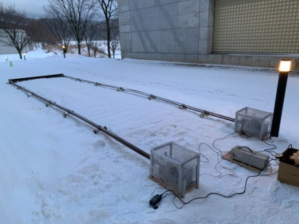
Fig. 16. “Setsu-ichi 2025” field test.
3.4. Snow Removal Testing
3.4.1. Test Overview
This section operates the developed “Setsu-ichi 2025” outdoors for actual ground snow-removal testing. “Setsu-ichi 2025” comprises commercial 100 V power supply, two Type-SK telescopic mechanisms (Unit 1 on left and Unit 2 on right facing extension direction), and a plastic snow-removal blade (Iron eaves gutter \(120 \times 1800\), Panasonic). The blade length is 1.8 m. To prevent tape bending inside the reel from excessive extension, extension was limited to 7 m (Fig. 16). “Setsu-ichi 2025” is designed to remove snow frequently before accumulation, therefore, testing was only conducted on fresh snow. Synchronization of the two Type-SK units was achieved through simple operation command signals (switches).
3.4.2. Results
Testing was conducted outdoors at \(-\)1°C temperature, 70% humidity, with 15 cm snow depth (3 cm fresh snow). Fig. 17 shows the removed snow on the blade. Electronic cam ratios were set to 0.95 for Unit 1 and 0.9 for Unit 2. During extension, the blade pushed a certain amount of snow while moving up and down to overcome excessive snow amounts, operating as intended. During the experiment, both Unit 1 and Unit 2 extended the snowplow blade while leveling snow. Occasionally, the metal tape unwinding happened inside the Type-SK with this leveling stress, causing the extension operation to stop. In such cases, recovery was possible by manually rewinding the tape onto the reel and tightening the anti-unwinding belt, allowing the extension to resume. During contraction, both Unit 1 and Unit 2 operated without problems, removing fresh snow. However, when a certain amount was exceeded, the blade moved up and down, riding over some snow that should have been removed.
3.5. Discussions
During the performance evaluation, the time difference between units was attributed to differences in the double-speed chain tension and clearances in the unwinding prevention chain and transition guides. The approximation curves fit quadratic functions; hence, the metal tape extension speed under ideal conditions should be a linear function, as expressed in Eq. (8):
| \(v(t)\) : | Metal tape feed speed |
| \(\omega\) : | Reel angular velocity (constant) |
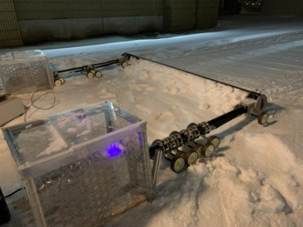
Fig. 17. Powder snow-removal task.
The results of the compression load test indicates that 250 N represents the Type-SK maximum allowable compression load. Additionally, in the compression load test, greater extension length resulted in smaller compression load because greater extension length means longer distance between the binding rings, causing the metal tape to bend earlier under the compression load. In both the compression load test and snow-removal test, the issue of the telescopic mechanism stopping owing to the load during extension is primarily caused by a gap formed in the metal tape inside the reel because the electronic cam ratio is lower than the ideal value. This problem arises from the uneven coating of the anti-slip spray and coating delamination during operation. The anti-slip spray is a type of semi-transparent synthetic rubber particle, and it is difficult to spray identically through a total 17 m length of the tape. Moreover, it is evident that the coated layer is delaminated by traveling through the tape-binding rings. Furthermore, it is believed that the constant compressive load from snow caused bending that did not occur during operation without a compressive load. To prevent bending of the metal tape after ejection from the main body, either increasing the left-right clearance at the fold section or reinforcing the rigidity from the fold section to the blade-mounting section is necessary. The retraction process is relatively straightforward. The tensile load tightens the metal tape, enabling operation without relying on the anti-unwinding chain, thereby reducing the difficulty of this operation. Regarding the issue of blades moving up and down and shedding snow when excessive snow accumulates on snowplow blades, the benefit is that they do not get stuck because of excessive snow. This can be resolved by removing snow. If snow shedding remains a problem, it can be addressed by modifying the blade shape or increasing the blade mass.
4. Conclusions
4.1. Summary
Measurement results revealed that Type-SK telescopic mechanism operation requires approximately 40 minutes for extension, 32 minutes for contraction, and 1 hour 12 minutes for a complete cycle. Maximum tensile load is avg. 311 N, with a maximum compression load of avg. 253 N at 0.5 m, 164 N at 4.0 m, and 114 N at 7.5 m extension, demonstrating the capability of snow-removal operations. Furthermore, synchronized operation using simple operation command signals (switches) achieved approximately \(1.8 \times 7\) m snow removal. This study aimed to achieve a stable extension from 0 to 7.5 m using materials with minimal outdoor operation degradation. Stable telescopic operation under no load or tensile load was achieved; however, stable operation under compression load could not be performed owing to inability to accurately adjust the electronic cam ratio.
4.2. Future Challenges and Prospects
The current challenge is stable operation under a compression load. This requires accurate adjustment of the electronic cam ratio. However, the increased metal tape thickness from uneven anti-slip coating applications makes this difficult. Additionally, this study considered future conversion to physical cams, but metal tape thickness increase from the anti-slip coating creates individual differences in the cam ratio and changes the ratio with coating removal or reapplication, making anti-slip coating and physical cam combination difficult. At this point, we are evaluating other materials that could form a more stable coating with 0.02 mm on both sides of the tape, and its anti-slip ability is positive. We need more trials with the materials, however, it will be alternative candidates for the system. In particular, some forms of continuously variable transmission mechanisms are considered necessary. If physical cams are abandoned and electronic cams are adopted, connecting the reel axis to slide rails instead of swing arms and mounting the main motor on the slide rails can simplify the transition guide structure. Furthermore, the main motor and reduction gear required approximately 1 hour 12 minutes for a complete cycle. Currently, the operating speed of Setsu-ichi is slow, requiring over an hour for a single pass of the snowplow blade. The cause is the use of a hobby motor rated at 7.2 V and approximately 40 W, operated at 12 V to drive the reel. However, this motor is inherently underpowered. The reason for selecting this motor was to first verify the operation using a hobby motor, anticipating situations without commercial AC power, such as snow removal from suburban vinyl greenhouses, enabling prolonged operation on a 12 V battery. In urban areas, commercial AC power ranging from 100 V to 240 V is available, allowing for replacement with a higher-output motor and faster snow removal. Other problems include insufficient rigidity of the custom unwinding prevention chain, which causes deformation and breakage. Solving these problems would enable not only the completion of an automated roof snow-removal system, but also applications to other life support uses as a linear telescopic mechanism. Research on soft robotics, a field that uses flexible structures, has recently been actively pursued. This study focuses on safety against unexpected contact during operations 18 and applications that actively leverage flexibility 19. The over 7-meter-long extensible mechanism demonstrated in this study, when combined with others, holds promise for new pioneering applications. For instance, instead of existing robots that absorb impacts by elastically controlling their joints 20, simpler linear mechanisms can potentially achieve equivalent functionality. Furthermore, a similar concept has been achieved using different materials; multiple carbon plates bound together with belts to allow folding have been reported as a retractable frame for a large, mobile 3D printer 21. Applications for these durable, long-span structures are expected to be diverse and extend beyond this specific example. We will continue our research to ensure the early societal implementation of the results of this study.
Acknowledgments
This study was supported by JSPS KAKENHI Grant Number: JP25K08239.
- [1] S. Nishida, “Snow Removal Device,” Patent No.EP1881127A1, US2007‑0205308A1, 2007.
- [2] B. P. Jelle, “The challenge of removing snow downfall on photovoltaic solar cell roofs in order to maximize solar energy efficiency—Research opportunities for the future,” Energy and Buildings, Vol.67, pp. 334-351, 2013. https://doi.org/10.1016/j.enbuild.2013.08.010
- [3] J. Wu et al., “Autonomous Robotic System for Snow Removal in Large-Scale Photovoltaic Arrays,” IEEE Access, Vol.13, pp. 141547-141559, 2025. https://doi.org/10.1109/ACCESS.2025.3597534
- [4] A. Chatten et al., “Vehicle Roof Snow Removal,” Patent No.US2019/0210573 A1, 2019.
- [5] T. Saito, “Manipulator Mechanism,” Patent No.PCT/JO2007/066233, 2007.
- [6] T. K. Saito et al., “300-N Class Convex-Based Telescopic Manipulator and Trial for 3-DOF Parallel Mechanism Robot,” J. Robot. Mechatron., Vol.33, No.1, pp. 141-150, 2021. https://doi.org/10.20965/jrm.2021.p0141
- [7] H. A. Farrand, “Rule,” US Patent 1,402,589, 1922.
- [8] W. Dubilier, “Collapsible Rod,” US Patent 2,130,993, 1938.
- [9] A. H. Bohr et al., “Extensible and Retractable Member,” US Patent 3,213,573, 1965.
- [10] D. S. Crouch, “Mars viking surface sampler subsystem,” Proc. of the 25th Conf. on Remote Systems Technology, pp. 141-152, 1977.
- [11] L. H. Widegren, “Extensible Jib, Mast or the Like,” US Patent 3,371,801, 1968.
- [12] C. D. Woodruff and G. E. Woodruff, “Apparatus and Methods for Providing Aretractable Mast,” US Patent 9,267,640, 2016.
- [13] K. Sekino et al., “Ultrawide Telescopic Actuator for Haptics Presentation based on Clustered and Elastic Convex Tapes,” 2022 Int. Conf. on Advanced Mechatronic Systems (ICAMechS2022), pp. 174-177, 2022. https://doi.org/10.1109/ICAMechS57222.2022.10003342
- [14] K. Inomata et al., “Wide Range and Highly Durable Telescopic Manipulator Mechanism by Aggregated Convexes,” The Proc. of JSME Annual Conf. on Robotics and Mechatronics (Robomech2013), Article No.1P1-P22, 2013 (in Japanese). https://doi.org/10.1299/jsmermd.2013._1P1-P22_1
- [15] T. K. Saito et al., “Roof Snow Removal System with Wide Range Telescopic Manipulator Mechanism,” The Proc. of JSME Annual Conf. on Robotics and Mechatronics (Robomech2016), Article No.2P2-09b1, 2016 (in Japanese). https://doi.org/10.1299/jsmermd.2016.2P2-09b1
- [16] K. Kobayashi et al., “8-meter Class Long Convex Tape Based Telescopic Mechanism for Roof Snow Removal Robot,” The Proc. of JSME Annual Conf. on Robotics and Mechatronics (Robomech2025), Article No.1A1-D11, 2025 (in Japanese). https://doi.org/10.1299/jsmermd.2025.1A1-D11
- [17] T. K. Saito et al., “Convex Tape Based Telescopic Cane for Life Support,” The Proc. of JSME Annual Conf. on Robotics and Mechatronics (Robomech2025), Article No.1P1-G12, 2025 (in Japanese). https://doi.org/10.1299/jsmermd.2025.1P1-G12
- [18] T. Nakamura, Y. Akamatsu, and Y. Kusaka, “Development of Soft Manipulator with Variable Rheological Joints and Pneumatic Sensor for Collision with Environment,” J. Robot. Mechatron., Vol.20, No.4, pp. 634-640, 2008. https://doi.org/10.20965/jrm.2008.p0634
- [19] J. Tanaka, “Vacuum End Effector Equipped with an Expansion and Contraction Mechanism Using a Wound Thin Metal Plate,” J. Robot. Mechatron., Vol.34, No.2, pp. 430-443, 2022. https://doi.org/10.20965/jrm.2022.p0430
- [20] T. Sekine et al., “Landing Impact Simulation of a One-Legged Robot with a Series Elastic Actuator,” J. Robot. Mechatron., Vol.37, No.3, pp. 627-636, 2025. https://doi.org/10.20965/jrm.2025.p0627
- [21] S.-P. Jung et al., “Foldable and rollable interlaced structure for deployable robotic systems,” Sci. Robot., Vol.10, No.108, Article No.eadv4696, 2025. https://doi.org/10.1126/scirobotics.adv4696
- [a] “Status of Implementation of Measures for Heavy Snowfall Areas, Ministry of Land, Infrastructure, Transport and Tourism, Japan, February 2025,” (in Japanese). https://www.mlit.go.jp/policy/shingikai/content/001864515.pdf [Accessed January 10, 2026]
This article is published under a Creative Commons Attribution-NoDerivatives 4.0 Internationa License.