
Paper:
A Gripper Capable of Grasping, Caging, and Pressing for Food Decoration
Yitong Xue*
 , Sadao Kawamura**, and Zhongkui Wang***
*Graduate School of Science and Engineering, Ritsumeikan University
1-1-1 Nojihigashi, Kusatsu, Shiga 525-8577, Japan
**Ritsumeikan Global Innovation Research Organization, Ritsumeikan University
1-1-1 Nojihigashi, Kusatsu, Shiga 525-8577, Japan
***Department of Robotics, Ritsumeikan University
1-1-1 Nojihigashi, Kusatsu, Shiga 525-8577, Japan

Food decoration usually requires a robotic system to perform multiple motions such as grasping, reorientation, and pushing. In this study, a novel gripper capable of grasping, caging, and pressing was developed with two-degrees-of-freedom featuring a parallel-drive mechanism and actively rotatable fingers. By employing two motors and two rack-and-pinion mechanisms, the system enables the simultaneous opening-closing and rotational motions of multiple fingers. This enables the grasping and caging of a target object. With the help of the inverted V-shaped fingers, the gripper can realize pressing motion after placement for stabilizing food decoration. To control the gripper, a kinematic model was derived to relate motor motions to finger motions. Experiments were conducted to decorate chestnuts on a dorayaki and the results revealed that a pressing motion is essential for stable decoration. Additionally, experiments on grasping various fragile food items demonstrated the effectiveness of the caging motion.
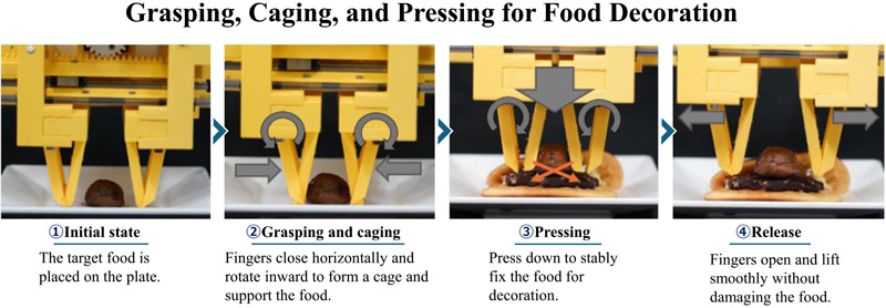
Grasping, caging, and pressing
1. Introduction
In food-processing environments, picking randomly stacked food items is a common yet labor-intensive task. Workers are often required to engage in prolonged periods of repetitive operations, leading to elevated risks of physical and mental stress, illness-related attrition, and premature retirement 1,2. Consequently, promoting the automation of such processes and reducing workload has become an urgent necessity.
Against this backdrop, robot-based automatic picking systems have attracted significant attention as an effective means 3,4,5. The design of the gripper, which serves as the core component of the system, has become an important research topic 6,7. However, many food products are nonrigid and fragile, and the risk of damage during grasping by robotic systems remains a major obstacle. For example, soft objects such as fruits and confectioneries can easily be deformed or damaged upon contact with highly rigid gripping mechanisms 8.
In recent years, soft grippers have been developed to address this challenge. When the gripper deforms upon contact with the target object, the contact area increases, thereby enhancing the frictional force and reducing the risk of damage 8. Low et al. 9 proposed a multifunctional soft gripper that integrated a finger posture adjustment mechanism with sensor feedback, thereby improving the adaptability to diverse objects. Similarly, Hao et al. 10 developed a universal soft pneumatic gripper with a variable-length structure to enhance its capability for manipulating compliant objects. However, as reported by Libby et al. 11, soft materials can undergo fatigue and degradation during extended use, potentially diminishing their accuracy as actuators. Therefore, durability remains a critical challenge for soft grippers.
In contrast, rigid grippers offer high durability, precise controllability, and the capacity to handle heavy loads, making them advantageous for many grasping tasks 12. Parallel and rotational grippers are the most extensively studied robotic grippers 13. The two-finger parallel gripper is the most prevalent type of gripper, accounting for approximately 85% of the market share. Because of its simple mechanical structure, low cost, high reliability, and low control complexity, this type of gripper is widely used in industrial pick-and-place operations. Prior studies have demonstrated that the geometry, texture, and compliance of the finger surface play critical roles in determining the grasp robustness. However, most rigid grippers rely primarily on friction to grasp objects in the horizontal direction, which inherently increases the risk of slippage-induced grasp failures. Specifically, when an excessive gripping force is applied to ensure sufficient friction, object deformation, or even damage, may occur. To address this issue, practitioners often employ ad hoc solutions, such as attaching rubber caps or wrapping textured tape, to enhance the gripping performance 14. Furthermore, novel fingertip designs integrating soft elastic shells with hard pins have been introduced to adjust the friction coefficient and improve grasp stability 15. Similarly, Chavan-Dafie et al. proposed pneumatic shape-shifting fingers that enable parallel-jaw grippers to achieve diverse contact modes and robust grasping by altering finger geometry 16, whereas Ward-Cherrier et al. developed a 3D-printed rigid gripper equipped with tactile sensors to enable high-precision grasping operations 17.
Unlike parallel-jaw grippers, angular grippers can provide supporting forces from beneath an object, thereby reducing the reliance on friction, and have been widely used in small-part handling applications. For instance, PHD Inc. developed the GRV series of compact precision angular pneumatic grippers that achieved high performance and long service life through finger rotation a. SGB series angular grippers from SCHUNK and PB series grippers from Gimatic are also widely deployed in industry, featuring simple and reliable structures with strong corrosion resistance b,c. Compared to rigid angular grippers, anthropomorphic robotic hands usually have multiple degrees of freedom, enabling enveloping or caging grasps. Ciocarlie et al. proposed the Velo gripper, a tendon-driven design actuated by a single motor that can passively adapt to the object being grasped and naturally envelop it with fingers 18. Furthermore, Sun et al. presented a modular gripper finger actuated by antagonistic wires and shape memory alloy springs, allowing active adjustment of the grasping posture to better mimic human hand characteristics 19. Such underactuated enveloping grippers not only support objects from below but also achieve multipoint contact and maintain grasp stability even during high-speed motion. In addition, Rojas et al. proposed a GR2 gripper, based on an underactuated mechanism, and demonstrated both the feasibility and grasp stability of in-plane manipulation under open-loop control 20.
Most existing grippers, including soft and rigid grippers, can realize parallel grasping and caging or enveloping separately, and very few grippers combine both grasping strategies, such as the scooping-binding gripper 21. Food decoration usually requires a pressing motion after the pick-and-place operation to ensure stable decoration. To this end, this paper presents a novel gripper capable of parallel grasping, caging, and pressing for food decoration. The gripper consisted of two motors, two rack-and-pinion mechanisms, and two pairs of fingers (Finger 1 and Finger 2) as shown in Fig. 1(a).
To demonstrate its application for food decoration, we consider the preparation of chestnut dorayaki as a representative task. Chestnut dorayaki is a traditional Japanese sweet consisting of two fluffy pancakes filled with sweet red bean paste (anko), often decorated with a chestnut placed on top of the filling. As shown in Fig. 1(a), both pairs of fingers are capable of horizontal motion, while Finger 2 can additionally rotate around its axis. Fig. 1(b) illustrates the grasping and caging phases where the gripper closes horizontally, while Finger 2 rotates to support the object from below. The two pairs of fingers thereby form a caging configuration that stabilizes the grasp. Fig. 1(c) shows the placement phase, during which Finger 2 rotates outward to disengage smoothly from the underside of the object, allowing the chestnut to be gently placed on the anko surface. Finally, as shown in Fig. 1(d), the pressing action is executed by the robotic arm to secure a stable decoration of the chestnut with the help of Finger 1.
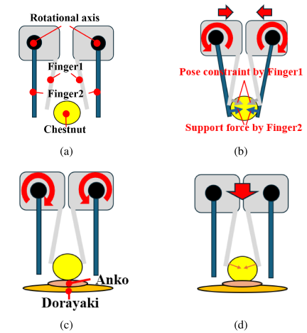
Fig. 1. Schematic illustration of the sequential operation of the proposed gripper during the chestnut decoration task: (a) initial state; (b) grasping and caging phase; (c) placement phase; (d) pressing action.
The main contributions of this study can be summarized as follows:
-
A gripper was developed that combined parallel and variable-angle motions, enabling grasping, caging, and pressing to satisfy the complex requirements of food-decoration tasks.
-
The gripper achieved both translational opening-closing and rotational motions using only two motors and two rack-and-pinion mechanisms, thereby providing a low-cost and efficient actuation method.
-
A kinematic model is established to map motor motions to finger motions and motor torques to grasping forces, thereby forming a theoretical basis for precise motion and force control.
-
Experiments on decorating a chestnut on a dorayaki and various fragile food items confirmed that pressing motion is essential for stable food decoration and effectiveness of gripper design for the stable handling of fragile objects.
2. Gripper Design and Manufacture
2.1. Driving Principle
Figure 2 shows a schematic of the operating principle of the gripper. The gripper consisted of two motors (Motor 1 and Motor 2), two rack-and-pinion mechanisms (A and B), and two pairs of fingers (fixed Finger 1 and rotatable Finger 2). Motor 1 and mechanism A were used to generate the parallel opening-closing motion of Finger 1 and Finger 2 for grasping the target object. Motor 2 and mechanism B were used to generate the rotational motion of Finger 2 for caging the target object from below. The pinion gear shown in red was designed to convert the rack motion of B to rotational motion of Finger 2. With this design principle, the parallel and rotational motions of the two pairs of fingers can be realized using only two motors. The detailed structural designs of these mechanisms are described in the following subsections.
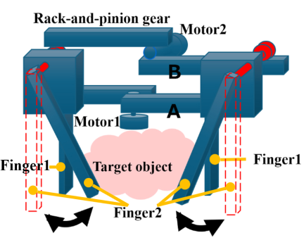
Fig. 2. Driving principle of the gripper.
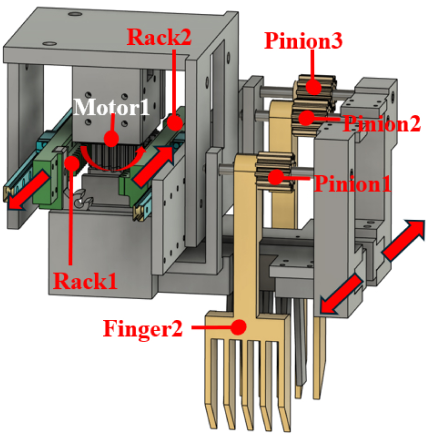
Fig. 3. Opening-closing mechanism of the gripper.
2.2. Opening-Closing Mechanism
The opening-closing motion of Finger 1 and Finger 2 is realized by the opening-closing mechanism as shown in Fig. 3, which is driven by Motor 1 and rack-and-pinion mechanism A. The rotation of Motor 1 causes Rack 1 and Rack 2 to move parallel in opposite directions to each other. The fingers are connected to the two racks, therefore, they can perform open-and-close motions accordingly.
Figure 4 shows the structure of the fingers. Since Rack 1 is connected to Finger 1 (left) and Finger 2 (left), both fingers move in the same direction as Rack 1. Similarly, as shown in Fig. 4(b), Finger 1 (right) and Finger 2 (right) are connected to Rack 2. Therefore, they also move in the same direction. For example, considering the opening operation of the gripper, when the motor rotates clockwise, Rack 1 and Rack 2 move in the directions indicated by the red arrows in Fig. 3. Consequently, the left and right fingers move outward, and the gripper opens.
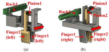
Fig. 4. Finger structure: (a) left-side fingers and (b) right-side fingers.
.png)
Fig. 5. Mechanism for rotating Finger 2.
2.3. Finger Rotation Mechanism
The rotational motion of Finger 2 is realized by Motor 2 and the rack-and-pinion mechanism B as shown in Fig. 2. By assembling Motor 2 and mechanism B into the opening-closing mechanism, the gripper design can be completed as shown in Fig. 5 (front view). When Motor 2 rotates, Rack 3 and Rack4 move in opposite directions. Since Rack 3 meshes with Pinion 1 and Rack 2 meshes with Pinion 3, Pinion 1 and Pinion 3 rotate in the same direction. Pinion 3 further meshes with Pinion 2, causing Pinion 2 to rotate in the direction opposite to Pinion 1. As shown in Fig. 5, the left Finger 2 is rigidly connected to Pinion 1, while the right Finger 2 is rigidly coupled to Pinion 2. Consequently, both fingers rotate inward or outward simultaneously, realizing the rotational motion of Finger 2.
This rotational mechanism enables Finger 2 to support the target object from below, thereby reducing its dependence on the frictional force during grasping. In contrast, Finger 1 does not rotate and only performs a horizontal motion. After grasping, Finger 1 and Finger 2 form a caging grasp with at least four-point contact with the target object. This caging grasp is beneficial for handling soft and fragile objects because it does not rely solely on frictional forces. In addition, Finger 1 was fixed at an inclined angle, which provided a downward force that ensured accurate and stable positioning during placement. This is particularly advantageous for decorating food items on soft substrates.
2.4. Gripper Manufacture
The manufactured gripper prototype is illustrated in Fig. 6. The primary mechanical components include gears, racks, fingers, servomotors, and linear guides. The gears, racks, and fingers were 3D printed using polylactic acid (PLA) material. Servomotors (XM430-W210-R, ROBOTIS) enable precise position control and indirect force control through current regulation, thereby allowing the gripper to realize multiple grasping modes. To ensure the smooth parallel motion of the racks, each rack is mounted on a miniature linear guide (Standard Block SSEBL8-110, MiSUMi). To reduce the size and weight of the gripper, its mechanical structure was revised several times and designed to be as compact as possible. The manufactured gripper prototype had overall dimensions of 170 mm (length), 133 mm (width), and 160 mm (height), with a maximum opening width of 130 mm. The total mass of the gripper prototype, including the servomotors, is approximately 1.3 kg.
.jpg)
Fig. 6. The manufactured gripper prototype.
3. Kinematic and Static Modeling
This section presents the kinematic and static models of the proposed gripper. First, based on the geometric constraints of the rack-and-pinion mechanisms, the relationships between the motor rotation angles and finger motions, including the opening-closing displacement and finger rotation, were formulated (kinematic modeling). Second, the mapping between the motor torques and generalized fingertip forces is derived (static modeling). These models establish a correspondence between the motor actuation and the motion/force characteristics of the gripper, thereby providing theoretical guidance for control design.
Figure 7 illustrates the definitions of the key variables used in the modeling, including the gripper opening width \(x\), effective radius of the motor-side pinion \(r_1\) for both Motor 1 and Motor 2, effective radius of the finger-mounted gear \(r_g\) for Pinion 1 through Pinion 3, moment arm of the rotatable finger \(\ell_\theta\), and external forces \(f_{dx}\) (horizontal direction) and \(f_{d\theta}\) (normal to the rotatable finger) applied to the fingertip. In addition, we define the rotational angle of Finger 2 as \(\theta\) (positive for inward rotation) and the output shaft angles of Motor 1 and Motor 2 as \(q_1\) and \(q_2\), respectively. Furthermore, we define the radius ratio \(r_2 = r_1/r_g\). In this study, the gripper opening width \(x\) is defined as positive in the opening direction. When viewed from the front of the gripper, the positive rotational directions of both \(q_1\) and \(q_2\) were defined as clockwise. With these sign definitions, identical motor velocities, that is, \(\dot{q}_1=\dot{q}_2\), produce a pure opening-closing motion without changing the rotational angle of Finger 2, as expressed in Eq. (1).
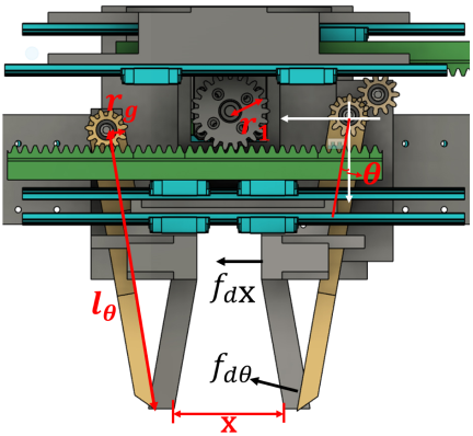
Fig. 7. Definition of variables in the gripper kinematic model.
Assuming rigid-body motion and quasi-static conditions, the geometric and velocity relationships of the gripper can be expressed as:
For the static model, let the generalized force associated with the gripper coordinates \([x,\,\theta]^\top\) be denoted as \(w = [f_x,\,\tau]^\top\), where \(f_x\) is the resultant force along the horizontal opening direction and \(\tau\) is the torque around the finger rotational axis. By applying the principle of power conservation, the mechanical power on the motor side is equal to that on the gripper side, yielding:
Under contact conditions, let the external fingertip forces be \([f_{dx},\,f_{d\theta}]^\top\), where \(f_{dx}\) acts along the horizontal direction of the gripper and \(f_{d\theta}\) is normal to the rotatable (yellow) finger. By introducing the moment arm \(\ell_\theta\), the generalized force can be equivalently expressed as:
For control purposes, the inverse mapping from the desired gripper velocities \([\dot{x},\,\dot{\theta}]^\top\) to the motor velocities was obtained directly from Eq. (1):
In summary, the developed model systematically analyzes the relationship between motor rotation angles and the finger opening width of the gripper and rotation angle, as well as the mapping between motor torques and fingertip forces. Based on these formulations, the motor position control can be directly applied to achieve precise control of finger opening and rotation, whereas current regulation enables indirect torque control to implement the force control of the gripper. This provides a theoretical foundation for ensuring the stability and versatility of grippers in different operating modes.
4. Experiments
In this section, we present the experiments characterizing the capabilities of the developed gripper for food grasping and decoration. Two experiments were conducted to validate the necessity of using two pairs of fingers and to showcase the capabilities of the developed gripper to perform food grasping and decoration of dorayaki.
4.1. Experimental Setup
The experimental setup is illustrated in Fig. 8. The gripper was mounted at the end of a 6-DOF robotic manipulator (UR5e, Universal Robot) and a typical pick-and-place motion was programmed for testing. In our experiments, we reproduce a decoration operation of dorayaki. After the food item was placed on top of the anko, a pressing motion was applied to stabilize the placement. For the parallel opening-closing motion, position control was applied to Motor 1 with the opening width determined according to the measured size of the target object. For the caging motion, force control was applied to Motor 2 by monitoring the motor current. Because friction exists among the mechanical components, such as the rack-and-pinion mechanisms, gears, and linear guides, it is difficult to accurately estimate the actual fingertip force using only the motor current or the theoretical torque model. Therefore, the output force of Finger 2 under the force-control condition was measured using a digital force gauge (ZTS-5N, IMADA). The measured output force of Finger 2 was approximately 2 N. In the present experiments, the same force conditions were used for all five food items because the main objective of this study was to evaluate the effectiveness of the proposed gripper structure. Therefore, the output force is not individually adjusted according to the shape or weight of each food item.
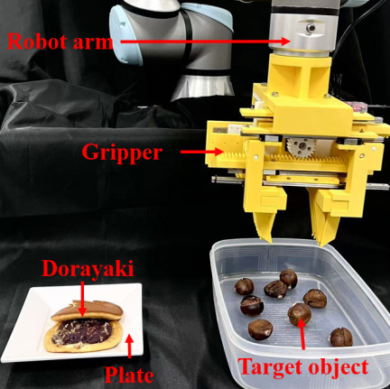
Fig. 8. Experimental setup for dorayaki decoration tests.
4.2. Gripper Characterization
To evaluate the advantages of the proposed gripper design and verify the necessity of employing two sets of fingers, a series of experiments were conducted. As shown in Fig. 9, two alternative configurations were tested by selectively removing one set of fingers and re-performing the dorayaki decoration test. In the first configuration, Gripper 1 as shown in Fig. 9(a), Finger 1 was removed while Finger 2 was retained. Finger 2 was able to translate horizontally and perform angular rotation as indicated by the arrows. In the second configuration, Gripper 2 as shown in Fig. 9(b), Finger 2 is removed, leaving only Finger 1 that executes horizontal linear motion. Thirty dorayaki decoration trials were conducted for each gripper configuration.
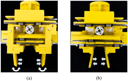
Fig. 9. Different gripper configurations: (a) Gripper 1 with only Finger 2 and (b) Gripper 2 with only Finger 1.
Gripper 1 successfully grasped the chestnut and translated it to the desired location; however, it was difficult to place the chestnut stably on the anko. Experimental snapshots of the placement performance of Gripper 1 are shown in Fig. 10. Although the chestnut was initially placed in the correct position (Fig. 10(a)), it rolled after release (Fig. 10(b)), resulting in an undesired displacement outside the anko. This reveals the necessity of a pressing operation during decoration.
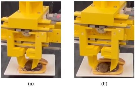
Fig. 10. Placement performance with Gripper 1: (a) initial placement position and (b) chestnut rolling after release.
Table 1. Success rate of using Gripper 2.
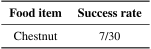
For Gripper 2, it was difficult to stably grasp and translate chestnuts. The results for Gripper 2 are presented in Table 1. Among the 30 grasping trials, 23 failures occurred during lifting owing to dropping, yielding a success rate of only \(7/30\). A representative failure case is shown in Fig. 11, where although the chestnut was successfully translated above the anko before placement (Fig. 11(a)), it fell during the following process (Fig. 11(b)).
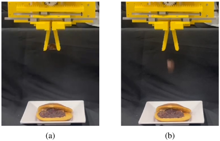
Fig. 11. Failure case with Gripper 2: (a) chestnut positioned above anko and (b) chestnut dropped during placement.
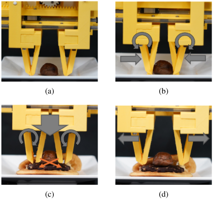
Fig. 12. Sequential operation of the gripper during the grasping and placement task: (a) initial state, (b) caging grasp, (c) pressing motion, and (d) chestnut release.
4.3. Food Grasping and Decoration Tests
Grasping and decoration tests were conducted on five food items, namely chestnuts, strawberries, sausages, broccoli, and mentaiko. Experimental snapshots of the chestnut decoration using the developed gripper are shown in Fig. 12. In the initial state (Fig. 12(a)), the gripper approached the chestnut without contact. As shown in Fig. 12(b), upon grasping, two pairs of fingers were actuated to form a caging configuration that securely enclosed the chestnut, ensuring a stable grasp. After translating the chestnut to the desired location, Finger 2 was rotated outward to disengage from the underside of the chestnut from the bottom and a pressing motion was then applied through the robotic manipulator, as shown in Fig. 12(c). Finally, the gripper opened horizontally to complete the chestnut decoration process, as shown in Fig. 12(d).
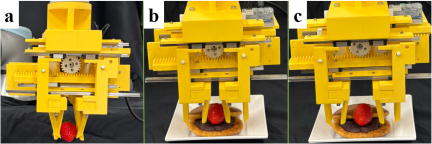
Fig. 13. Snapshots of the strawberry dorayaki decoration test: (a) grasping; (b) pressing after placement on the dorayaki; and (c) release.
In addition to chestnuts and strawberries, which were used as representative food items for dorayaki decoration, broccoli, sausages, and mentaiko were also selected to evaluate the applicability of the proposed gripper to food items with different object properties. Broccoli is an irregularly shaped object, sausage is an elongated object, and mentaiko is a soft and deformable object.
As shown in Fig. 1(b), Finger 2 provides support from below during the caging motion. This bottom support reduces the dependence on the frictional force between the object and fingers, thereby decreasing the required lateral gripping force and reducing the risk of damage to fragile food items. This function is particularly important for soft food items such as mentaiko, because the available frictional force is limited when excessive normal force must be avoided to prevent deformation or damage. Therefore, the conventional two-finger grippers may have difficulty grasping such objects, whereas the proposed gripper can stably support them from below.
By contrast, Finger 1 mainly provides a pose constraint for the target object. This constraint is effective for irregularly shaped or elongated objects such as broccoli and sausage. In particular, when an elongated object, such as a sausage, is not grasped near its center of mass, a rotational moment may be generated during lifting or transportation, which can cause the object to overturn and lead to grasping failure. The pose constraint provided by Finger 1 helps suppress undesired rotation and contributes to stable grasping. Thus, the combination of pose constraint by Finger 1 and bottom support by Finger 2 enables the proposed gripper to handle food items with different shapes, deformabilities, and frictional properties.
Additional snapshots of the tests are presented in Figs. 13 and 14 to demonstrate the applicability of the proposed gripper to food items other than chestnuts. Because strawberries were used as another representative food item for dorayaki decoration, the strawberry dorayaki test included grasping, pressing after placement, and release, as shown in Fig. 13. For broccoli, mentaiko, and sausage, the tests mainly focused on evaluating the grasping and caging capability of the proposed gripper; therefore, representative snapshots of grasping/caging and release are shown in Fig. 14.
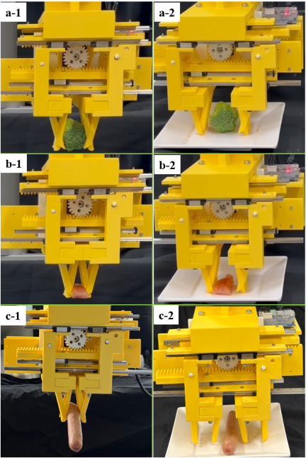
Fig. 14. Snapshots of grasping tests for the other food items: (a-1, a-2) broccoli, (b-1, b-2) mentaiko, and (c-1, c-2) sausage. For each food item, the first image shows the grasping/caging state and the second image shows the release state.
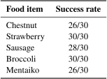
Thirty trials were conducted for each food item, and the resulting grasp success rates are listed in Table 2. The results reveal that the developed gripper can successfully grasp all food items with a high success rate despite the fragile and slippery properties of some items, such as strawberries and mentaiko. This validates the caging-grasp configuration of the gripper.
Table 2. Success rates of grasping for each food item.
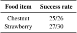
In addition, placement accuracy was evaluated for two target objects: chestnuts and strawberries. In the placement evaluation, we confirmed whether the food items remained stable on the anko; cases where the food items toppled or slipped off were evaluated as placement failures. The evaluation results are presented in Table 3.
Table 3. Success rates of placement for the food items.
4.4. Discussion
The grasping success rates in Table 2 were 86.7% or higher for all tested food items, and the placement success rates in Table 3 were \(25/26\) for chestnuts and \(27/30\) for strawberries. These results indicate the potential applicability of the proposed gripper for food-decoration tasks. However, for practical food plating applications in food manufacturing, further improvements in repeatability and robustness are necessary.
The experimental results were further interpreted by analyzing the failed trials. In chestnuts, failures mainly occur during the grasping, caging, and placement stages. The shape of the chestnuts varied among the samples, with some samples having a hemispherical shape. When such a chestnut was placed with its flat surface facing downward, Finger 2 could not easily move underneath the object, resulting in insufficient bottom support during caging. In the placement stage, the rounded shape of the chestnuts also caused rolling on the soft anko surface, leading to placement failure in some trials.
In sausages, failures mainly occur during lifting and transportation. This was caused by the combination of the small object width, relatively large mass, and limited structural rigidity of the prototype. Sausages had the largest mass among the tested objects (32 g). As the gears, racks, and fingers were fabricated from PLA, slight undesired deformation could occur in the rack-and-pinion mechanism during lifting. This deformation could change the relative position of the fingers and reduce the effective support from Finger 2, causing a narrow and relatively heavy object to slip out from between the fingers.
In mentaiko, the failures were mainly related to soft and slippery surfaces. Because an excessive normal force may deform or damage an object, the available frictional force is limited. Therefore, stable grasping is difficult for conventional two-finger grippers that rely primarily on friction. In contrast, the proposed gripper can support the object from below using Finger 2, which explains why mentaiko could be grasped in most trials. Based on this failure analysis, future work will focus on improving the approach and caging strategy for objects with flat-bottom or hemispherical shapes, optimizing the release and pressing motion for rounded objects, and replacing the PLA components of the rack-and-pinion mechanism with metal parts to improve the structural rigidity and transmission accuracy. The experimental results highlighted the necessity of using two finger sets in the proposed gripper. When only Finger 2 was employed (Gripper 1), grasping was successful, but stable placement could not be guaranteed owing to the rolling and slipping of the food item. Conversely, when only Finger 1 was used (Gripper 2), the grasping success rate significantly reduced with frequent object dropping. These findings confirm that the cooperative function of both finger sets is indispensable. Finger 1 provides stable lateral positioning and pressing motion, while Finger 2 generates a supporting force from below, thereby reducing reliance on friction and enabling precise and robust placement of food items.
5. Conclusion
In this study, a novel two-degree-of-freedom gripper was developed, featuring a parallel-drive mechanism and actively rotatable fingers. The gripper performs grasping, caging, and pressing actions using only two motors and two rack-and-pinion mechanisms, ensuring structural simplicity and a lightweight design. This design also allows the actuators to be located at the gripper base and avoids adding actuators to the moving fingers. With the help of an inclined finger (Finger 1), the gripper can press after placement to stabilize the food decoration. The opening angle and workspace can be adjusted according to the object size and shape, thereby enhancing the versatility.
A kinematic model was derived to relate motor inputs to finger motions. Experiments on dorayaki chestnut decoration confirmed the necessity of pressing for a stable placement. Additional tests with fragile items such as strawberries, broccoli, sausages, and mentaiko demonstrated the effectiveness of caging and pressing motions in food handling. Although effective, the gripper exhibits limitations in its actuation; minor velocity discrepancies between the two motors occasionally cause undesired finger rotation, thereby increasing the risk of food damage. Future work will focus on improving the motor synchronization and developing compensation strategies to ensure stable and safe operation.
Acknowledgments
This work was supported in part by JSPS KAKENHI under Grant Number JP24K00856, and in part by JST SPRING under Grant Number JPMJSP2101.
- [1] S. Neupane, P. Virtanen, T. Luukkaala, A. Siukola, and C.-H. Nygård, “A four-year follow-up study of physical working conditions and perceived mental and physical strain among food industry workers,” Applied Ergonomics, Vol.45, No.3, pp. 586-591, 2014. https://doi.org/10.1016/j.apergo.2013.08.010
- [2] L. Sell, “Predicting long-term sickness absence and early retirement pension from self-reported work ability,” Int. Archives of Occupational and Environmental Health, Vol.82, pp. 1133-1138, 2009. https://doi.org/10.1007/s00420-009-0417-6
- [3] Y. Xue, Z. Qiu, H. Zhang et al., “A synthetic dataset for robotic food handling system,” 2024 IEEE/SICE Int. Symp. on System Integration (SII), pp. 410-415, 2024. https://doi.org/10.1109/sii58957.2024.10417293
- [4] Z. Wang, R. Kanegae, and S. Hirai, “Circular shell gripper for handling food products,” Soft Robotics, Vol.8, No.5, pp. 542-554, 2021. https://doi.org/10.1089/soro.2019.0140
- [5] Y. Zhang, Z. Wang, K. Kutani, and S. Kawamura, “A soft-containing gripper for high-speed handling of breadcrumb-coated oysters,” J. of Field Robotics, Vol.42, No.5, 2024. pp. 1976-1990, 2025. https://doi.org/10.1002/rob.22488
- [6] J. Hernandez, M. S. H. Sunny, J. Sanjuan, I. Rulik, M. I. I. Zarif, S. I. Ahamed, H. U. Ahmed, and M. H. Rahman, “Current designs of robotic arm grippers: A comprehensive systematic review,” Robotics, Vol.12, No.1, Article No.5, 2023. https://doi.org/10.3390/robotics12010005
- [7] C.-H. Liu, F.-M. Chung, Y. Chen, C.-H. Chiu, and T.-L. Chen, “Optimal design of a motor-driven three-finger soft robotic gripper,” IEEE/ASME Trans. on Mechatronics, Vol.25, No.4, pp. 1830-1840, 2020. https://doi.org/10.1109/TMECH.2020.2997743
- [8] Z. Wang, S. Hirai, and S. Kawamura, “Challenges and opportunities in robotic food handling: A review,” Frontiers in Robotics and AI, Vol.8, Article No.789107, 2022. https://doi.org/10.3389/frobt.2021.789107
- [9] J. H. Low, P. M. Khin, Q. Q. Han et al., “Sensorized reconfigurable soft robotic gripper system for automated food handling,” IEEE/ASME Trans. on Mechatronics, Vol.27, No.5, pp. 3232-3243, 2021. https://doi.org/10.1109/tmech.2021.3110277
- [10] Y. Hao et al., “Universal soft pneumatic robotic gripper with variable effective length,” 2016 35th Chinese Control Conf. (CCC), pp. 6109-6114, 2016. https://doi.org/10.1109/ChiCC.2016.7554316
- [11] J. Libby, A. A. Somwanshi, F. Stancati, G. Tyagi, A. Patel, N. Bhatt, J. Rizzo, and S. F. Atashzar, “What happens when pneu-net soft robotic actuators get fatigued?,” 2023 Int. Symposium on Medical Robotics (ISMR), 2023. https://doi.org/10.1109/ismr57123.2023.10130227
- [12] Z. Chen, D. Wu, Q. Guan, D. Hardman, F. Renda, J. Hughes, T. G. Thuruthel, C. Della Santina, B. Mazzolai, H. Zhao et al., “A Survey on Soft Robot Adaptability: Implementations, Applications, and Prospects,” arXiv preprint, arXiv:2506.19397, 2025.
- [13] Q. Lu, A. B. Clark, M. Shen, and N. Rojas, “An origami-inspired variable friction surface for increasing the dexterity of robotic grippers,” IEEE Robotics and Automation Letters, Vol.5, No.2, pp. 2538-2545, 2020. https://doi.org/10.1109/LRA.2020.2972833
- [14] M. Guo, D. V. Gealy, J. Liang, J. Mahler, A. Goncalves, S. McKinley, J. A. Ojea, and K. Goldberg, “Design of parallel-jaw gripper tip surfaces for robust grasping,” 2017 IEEE Int. Conf. on Robotics and Automation (ICRA), pp. 2831-2838, 2017. https://doi.org/10.1109/ICRA.2017.7989330
- [15] H. Fu and W. Zhang, “The development of a soft robot hand with PIN-array structure,” Applied Sciences, Vol.9, No.5, Article No.1011, 2019. https://doi.org/10.3390/app9051011
- [16] N. Chavan-Dafie, K. Lee, and A. Rodriguez, “Pneumatic shape-shifting fingers to reorient and grasp,” 2018 IEEE 14th Int. Conf. on Automation Science and Engineering (CASE), pp. 988-993, 2018. https://doi.org/10.1109/COASE.2018.8560472
- [17] B. Ward-Cherrier, N. Rojas, and N. F. Lepora, “Model-free precise in-hand manipulation with a 3D-printed tactile gripper,” IEEE Robotics and Automation Letters, Vol.2, No.4, pp. 2056-2063, 2017. https://doi.org/10.1109/lra.2017.2719761
- [18] M. Ciocarlie, F. M. Hicks, R. Holmberg, J. Hawke, M. Schlicht, J. Gee, S. Stanford, and R. Bahadur, “The Velo gripper: A versatile single-actuator design for enveloping, parallel and fingertip grasps,” The Int. J. of Robotics Research, Vol.33, No.5, pp. 753-767, 2014. https://doi.org/10.1177/0278364913519148
- [19] L. Sun, Y. Lan, B. Wang, and J. Li, “Design and analysis of modular gripper finger actuated by antagonistic wire and shape memory alloy springs,” J. of Robotics, Vol.2024, No.1, Article No.3620540, 2024. https://doi.org/10.1155/2024/3620540
- [20] N. Rojas, R. R. Ma, and A. M. Dollar, “The GR2 gripper: An underactuated hand for open-loop in-hand planar manipulation,” IEEE Trans. on Robotics, Vol.32, No.3, pp. 763-770, 2016. https://doi.org/10.1109/tro.2016.2562122
- [21] Z. Wang, H. Furuta, S. Hirai et al., “A scooping-binding robotic gripper for handling various food products,” Frontiers in Robotics and AI, Vol.8, Article No.640805, 2021. https://doi.org/10.3389/frobt.2021.640805
- [a] PHD, Inc., “Series GRV Compact precision angular pneumatic gripper.” https://www.automate.org/products/phd-inc/series-grv-compact-precision-angular-pneumatic-gripper [Accessed September 13, 2025]
- [b] SCHUNK SE & Co. KG, “SGB Angular/Radial gripper (Small, simple pressurized plastic angular gripper with spring return).” https://schunk.com/de/en/gripping-systems/angular/radial-gripper/sgb/c/PGR_384 [Accessed September 13, 2025]
- [c] Gimatic S.r.l., “PB series–2-jaw non-selfcentering angular pneumatic sprue gripper.” https://shop.gimatic.com/en/pb [Accessed September 13, 2025]
This article is published under a Creative Commons Attribution-NoDerivatives 4.0 Internationa License.