Research Paper:
Design of a Robot Arm Based on Human Structure for Humanoid Robots
Keita Kobayashi* and Akinori Sekiguchi**,†

*Sustainable Engineering Program, Graduate School of Engineering, Tokyo University of Technology
1404-1 Katakuramachi, Hachioji, Tokyo 192-0982, Japan
**Department of Mechanical Engineering, Tokyo University of Technology
1404-1 Katakuramachi, Hachioji, Tokyo 192-0982, Japan
†Corresponding author

In this study, we examined the frame model of a robot arm from the upper arm to the forearm based on human anatomy to develop a tendon-driven humanoid robot that incorporates human anatomical structures. We designed a 3D CAD model of a robotic arm incorporating human anatomical features, and evaluated its expected range of motion. The evaluation results demonstrated that incorporating human anatomical features resulted in an expanded range of motion compared to a structure without these features. In particular, the offset of the elbow joint affects the range of motion in flexion and extension of the elbow; it decreases the range of motion for extension but increases it for flexion. Similarly, the curvature of the ulna and radius affects the range of motion in forearm pronation and supination and decreases the range of motion for supination while increasing it for pronation. The prototype was able to perform the basic movements of elbow flexion and extension, as well as forearm pronation and supination; however, the pronation and supination movements were not smooth. Based on these findings, it can be concluded that incorporating human anatomical structures is sufficiently effective in enhancing the functionality of robot arms.
Robot arm based on human structure
1. Introduction
Humans perform many necessary tasks in workplaces, such as construction sites and nursing facilities. However, in modern times in Japan, there is growing concern over labor shortages 1, which may adversely affect these workplaces.
Research aimed at addressing labor shortages using humanoid robots has been actively conducted. Among these studies, research on the upper limbs is considered as important as bipedal walking, which is a major feature of humanoid robots. In particular, those that adopt tendon-driven mechanisms using wires are effective because the passive joints make it easier to ensure flexibility 2 and reduce the risk of injury due to human-robot collisions. Therefore, research on tendon-driven humanoid robots is being actively conducted.
Song et al. 3 developed a dual-arm robotic system, “LIMS2-AMBIDEX,” designed for high-speed manipulation tasks, with the goal of competing in the IROS2018 Robotic Challenge. This system employs a tendon-driven mechanism to achieve high precision and speed while ensuring safety. By placing all heavy actuators around the shoulder area, the mass beyond the shoulder was significantly reduced, thereby enabling both high-speed operation and enhanced safety. Although the unique wrist mechanism satisfies the performance requirements and can be considered highly effective, achieving a functionality equivalent to that of a human hand is challenging. One of the advantages of this robotic arm is its ability to exchange end-effector components. By swapping components such as flat plates or fingers, the system can achieve a variety of functions.
Fingers are indispensable for realizing a functionality equivalent to that of a human; however, in this robot arm, actuators for the fingers must be incorporated into the end-effector, making hand enlargement unavoidable. The muscles in the fingers are located in the forearm, allowing not only improved safety through tendon-driven mechanisms but also the ability to minimize the size of the fingers as much as possible.
As a potential approach, we propose the structure of the human body as an exemplary model. To achieve lighter and smaller hands, studies have utilized the advantages of tendon-driven mechanisms by positioning actuators away from the hands 4,5. Therefore, we believe that this approach is reasonable.
Kawaharazuka et al. 6 conducted research on the design and development of a forearm structure with a radius and ulna configuration that accurately mimicked human proportions, weight, muscle arrangement, and structure, and developed a humanoid robot named Kengoro 7. They succeeded in achieving dexterous movements that leveraged the advantages of the radius and ulna structures.
However, the elbow joint offsets and curvatures of the bones included in an actual human structure were not replicated. As the curvature of the radius and ulna is suggested to influence the range of motion, mimicking these features is considered to have significant benefits.
Among the studies on tendon-driven humanoid robots, few focus on the skeletal structure from an anatomical perspective, and even fewer closely analyze and mimic the human structure. Therefore, this study aimed to develop a tendon-driven humanoid robot that incorporates human structures. A frame model for developing the robotic arm from the upper arm to the forearm was examined.
2. Significance of Mimicking Human Structure and Analysis of Human Upper Limb
Based on the aforementioned background, this section explains the significance of mimicking human structures in the development of a tendon-driven robotic arm that incorporates human anatomy. Furthermore, it describes the structures and movements of human upper limbs.
2.1. Significance of Mimicking Human Structure
The significance of incorporating human structures into humanoid robots, which is a key element of this study, lies in the advantages of this approach. For instance, in the field of quadrupedal robots, Boston Dynamics’ “Spot” and “BigDog” 8 are well-known examples. These robots have skeletons similar to those of quadrupedal animals and excel at navigating rough terrain, which is a specialty of such animals. Therefore, mimicking the skeletons of quadrupedal animals in quadrupedal robots is a logical and effective design philosophy, provided that it suits the required functions. Based on this reasoning, this study argues that the incorporation of human structures into humanoid robots is highly effective.
2.2. Structures and Movements of Human Upper Limb
This section explains the structure and function of bones and joints based on “Functional Anatomy” 9, towards the development of a tendon-driven robot arm that incorporates human structure.
The human upper arm and forearm are composed of three bones: the humerus, ulna, and radius, as shown in Fig. 1(a). Flexion/extension of the elbow involves bending and straightening of the elbow joint, which operates through the humeroulnar and humeroradial joints. The fully extended position of the elbow is called the neutral position, and serves as the reference angle for joint movements.
The pronation/supination of the forearm, as shown in Fig. 1(b), involves rotational movement of the forearm. This movement is facilitated by the proximal and distal radioulnar joints. Pronation and supination of the forearm were enabled by the crossing of the ulna and radius bones, as shown in Fig. 1(b).
As shown on the left side of Fig. 1(b), termed pronation refers to the position in which the thumb points outward. Conversely, supination, as shown on the right side of Fig. 1(b), occurs when the forearm rotates and the thumb points inward. The intermediate position, where the thumb is upright, is termed the neutral position of the forearm.
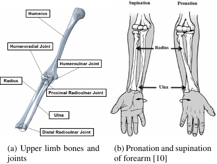
Fig. 1. The structure and movement of the upper limb
The range of motion for elbow flexion and extension with flexion considered positive, is approximately 150° in total. Starting from the neutral position at 0°, maximum flexion reaches 145° and maximum extension reaches \(-5\)°. For pronation and supination of forearm, with supination considered positive, the range of motion is approximately 175° in total. Starting from the neutral position at 0°, maximum pronation reaches \(-85\)° and maximum supination reaches 90°. These ranges of motion are constrained by the bones, muscles, and ligaments to prevent exceeding their limits.
The next section explains the characteristics and functions of the bones, joints, ligaments, and other related structures.
2.2.1. The Two Bones of the Forearm
The forearm is composed of two bones, and as previously mentioned, pronation/supination is achieved by the radius crossing over the ulna. This structure is present not only in humans, but also in quadrupedal animals. This structure contributes to the centralization of mass by allowing the placement of larger muscles closer to the body. Kawaharazuka et al. 6 presented three features of the two bones; here, we describe two of them. The first is the ability to achieve pronation and supination using only the radius, while keeping the ulna fixed to an object, such as during soldering or writing. The second is the ability to reduce the load on the blood vessels, nerves, tendons, and skin. Assuming that tendon-driven mechanisms are used to drive fingers to ensure human-equivalent functionality, the two bones of the forearm can prevent tendon twisting. Additionally, considering the incorporation of the skin as an outer layer to prevent external physical interference, which is a weakness of tendon-driven mechanisms, the ability to disperse skin twisting is a significant advantage.
From these points, it can be said that the two-bone method is superior to the direct-drive method using a rotary motor and that the two-bone structure of the forearm is well-suited for tendon-driven mechanisms.
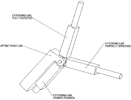
Fig. 2. An example of offset joints 11.
2.2.2. The Offset of Elbow Joints
The part of the humerus farther from the body is called the distal humerus, whereas the part of the ulna closer to the body is called the proximal ulna. These joints form the humeroulnar joint, which is responsible for elbow flexion and extension. The distal humerus was inclined forward at an angle of 30° to 45°, and similarly, the proximal ulna was inclined forward at the same angle. This characteristic offsets the center of rotation for flexion and extension from the long axes of the humerus and ulna, allowing for a greater range of motion. As shown in Fig. 2, this allows the arm to bend back 180°, contributing to an extended range of motion and improved stowability. Therefore, this design has been adopted in many industrial robots and manipulators 11. In addition, according to Kapandji 9, there is the advantage of providing space for the muscles located around the elbow.
2.2.3. The Curvature of Ulna and Radius
The two bones that comprise the forearm, radius, and ulna are curved, as shown in Figs. 3 and 4. They exhibit a curvature that bends posteriorly in the supinated position 12. This curvature allowed the concave curves of the two bones to face each other during pronation, enabling the distal end of the radius to move further posteriorly relative to the distal end of the ulna. This configuration achieved a wider range of motion during pronation/supination.
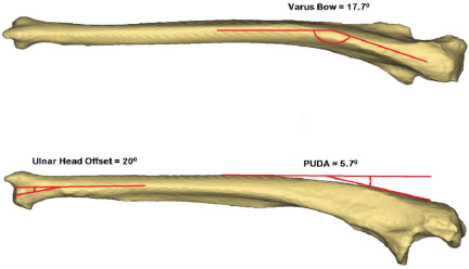
Fig. 3. The curvature of the ulna bone.
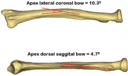
Fig. 4. The curvature of the radius bone.
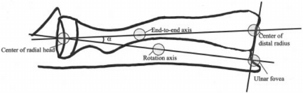
Fig. 5. The rotation axis of pronation and supination 13.
2.2.4. Annular Ligament
The annular ligament, which restricts the position of the proximal end of the radius, acts as a bearing to facilitate smooth pronation/supination, thereby assisting in the rotation of the radius. The annular ligament is attached to the ulna and moves while holding the radial head in place during the flexion/extension of the elbow.
2.2.5. The Rotation Axis of Pronation and Supination
The axis of rotation for pronation and supination of the forearm occurs around two distinct joints, as shown in Fig. 1, namely the proximal radioulnar joint and distal radioulnar joint. This axis is inclined towards the ulna as it approaches the distal end of the forearm, as shown in Fig. 5 13. Fig. 5 shows the angle \(a\) formed between the line connecting the centers of both ends of the radius and the axis of forearm rotation. This angle averaged 6.7°, ranging from 4.5° to 8.5°, enabling pronation and supination of forearm.
3. Consideration of Robot Arm Incorporating Human Structure and Design of Frame Model
Based on the findings in the previous section, we examined the robotic arm from the upper arm to the forearm to incorporate features of the human structure into an actual humanoid robot. Based on this examination, we designed a frame model for the robotic arm.
3.1. Overview of Robot Arm Aimed for Development
This section outlines the tendon-driven robot arm that incorporates human structure.
As the robot arm is intended to be incorporated into a humanoid robot, its applications include labor at construction sites and caregiving facilities. Specifically, these applications involve tools, such as screwdrivers, for fastening screws, opening and closing doors, and lifting individuals who require assistance. Based on these applications, the design requirements for the robot arm are as follows:
-
Capability of safely operating in proximity to humans
-
Able to use tools
-
Powerful with human-like range of motion
-
Capability for precise movement
Tendon-driven actuation is considered appropriate for ensuring safe operation in environments with people. This is because they reduce the risk of injuries resulting from collisions with nearby individuals or objects. Consequently, it enables safety in the labor environment. To achieve a human-equivalent size and range of motion, it is necessary to analyze the structure of the human upper limb and actively adopt the structural elements that contribute to the range of motion. To enable tool use, the end-effector was assumed to be composed of five fingers, similar to the human hand. This allows multiple fingers to operate accurately and independently, thereby facilitating work in environments similar to those humans work in. To achieve precise motion for efficient operation, advanced feedback control is required to manage force, position, and posture.
Table 1 lists the specifications of the robot arm developed in this study based on the above design requirements. Fig. 6 shows an image of the robot arm to be developed. To adapt well to labor environments, the weight and range of motion were set to values comparable to those of humans, and the lengths of the arm, humerus, ulna, and radius were determined based on multiple literature sources 12,13,14. In this study, the hand was not considered; instead, the design and validation focused on the structure of the forearm.
Table 1. The specification of the robot arm.

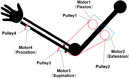
Fig. 6. Conception of the robot arm.
The joint constraints were implemented using hinge joints pierced with rods or shafts. This differs from the ligament-based constraints observed in humans and other animals. However, hinge joints aim to maintain a consistent center of rotation, facilitating subsequent design and analysis. Therefore, the carrying angle is also not replicated. The carrying angle is the acute angle formed between the long axis of the upper arm and the long axis of the forearm when the elbow and forearm are extended and supinated. Furthermore, considering the ease of placement in confined spaces and the need for high output, motors were chosen as the actuators.
The driving mechanism is tendon-driven, in which the motor rotation is transmitted through pulleys to drive via tensioned wires or strings. Therefore, more motors than the assumed degrees of freedom are required, and the robotic arm developed in this study requires four motors. The four motors actuate the flexion and extension of the elbow as well as the pronation and supination of the forearm through tension applied via wires or strings. Human muscles operate in complex and multifaceted manners. However, because of the use of hinge joints for joint constraints in this study, muscles that assist in the stabilization of movements, such as the anconeus, were deemed unnecessary. Therefore, a minimum of four motors was used. Although the muscles of the fingers are not the focus of this study and are thus not discussed in detail, it is assumed that they are positioned proximally in the forearm to centralize the mass, similar to those in humans.
Control was achieved through feedback using potentiometers to measure the angles for regulating elbow flexion/extension and forearm pronation/supination.
3.2. Design of Frame Model
Based on the specifications outlined in the previous section and the human anatomy, we designed a frame model of the robot arm developed in this study. This section explains each part of the designed frame model and discusses how human anatomy has been incorporated.
Figure 7 shows the frame model designed using the 3D CAD software. This model primarily consists of the humerus, ulna, and radius bones. In the robot arm’s frame model, all joints were constrained using hinge joints. The offset joints, as shown in Fig. 7, are each inclined 45° forward. Moreover, the forward offset distance from the long axis of the humerus to the axis of rotation at the elbow was set to 10.0 mm based on 15. This offset is expected to expand the range of motion achieved by the joint. The radius and ulna curvatures were incorporated into the frame model based on previous studies 12,16,17. The function of the annular ligament is replicated using bearings, which reduce resistance at the humeroulnar joint, humeroradial joint, proximal radioulnar joint, and distal radioulnar joint. Regarding the axis of rotation for the forearm, it is designed to replicate the line connecting the centers of both ends of the radius and the axis of rotation of the forearm, with an angle \(\alpha\), as shown in Fig. 5. It was designed to maintain a deviation within the range of 4.5° to 8.5°, as shown in Fig. 7 13. These joints and links constitute a closed-loop mechanism that enables two degrees of freedom: flexion/extension of the elbow joint and pronation/supination of the forearm.
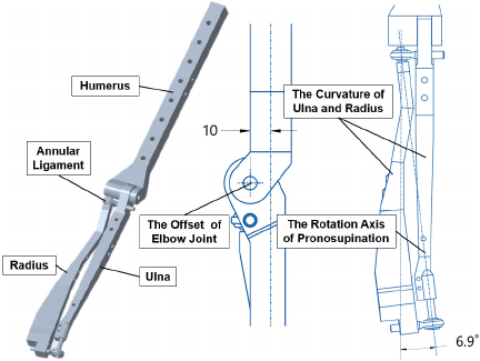
Fig. 7. The frame model of a robot arm designed using 3D CAD.
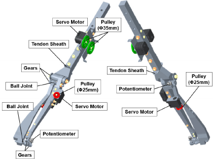
Fig. 8. Components of the robot arm prototype.
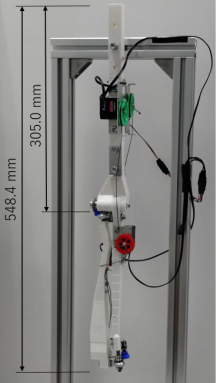
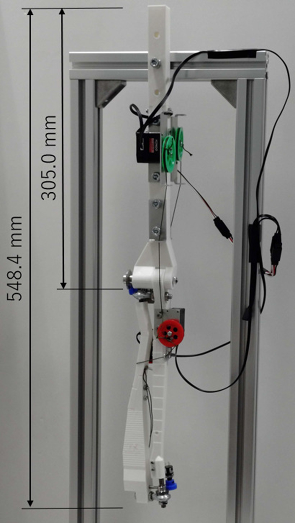
Fig. 9. Prototype of the robot arm.
4. Prototype of the Robot Arm
Based on the aforementioned design, a prototype of the robotic arm was fabricated. In this section, the components of the robot arm, which were designed to be equipped with servo motors, pulleys, and other elements to enable the actual operation, are described. The components of the robotic arm are shown in Fig. 8. The prototype of the robot arm constructed based on these components is shown in Fig. 9. Note that the purpose of the prototype robot arm was to enable basic movements of elbow flexion and extension, forearm pronation, and supination, and the output torque was not considered.
4.1. Servo Motor
As shown in Fig. 8, two servo motors were fixed to the humerus, each responsible for performing flexion and extension movements. Similarly, two servo motors were fixed to the ulna of the forearm, each responsible for pronation and supination movements.
Pulleys are attached to the output shafts of all the servo motors, and the polyethylene lines wound by the pulleys pass through relay components serving as tendon sheaths before being anchored to the skeleton.
The KRS-3304R2 ICS manufactured by Kondo Kagaku Co., Ltd. was used for the servo motors responsible for flexion and extension, whereas the smaller KRS-3204R2 ICS model from the same company was selected for pronation and supination. Both types allow the acquisition of their current positions via serial communication; in particular, smaller servo motors were chosen for the pronation and supination mechanisms.
Table 2. Specifications of the servo motor used for flexion/extension and pronation/supination.

The specifications of the servo motors used are listed in Table 2.
4.2. Pulley
The diameter of the pulley fixed to the servo motor responsible for flexion and extension was selected based on the calculated value required to achieve the maximum range of motion of the elbow joint. Fig. 10 shows a simplified side-view diagram of various positions of the elbow joint. In this figure, the rotation center of the elbow joint is represented by point O \((0, 0)\), point Q \((-10.5, 43.5)\) corresponds to the tendon sheath through which the polyethylene line passes, and point P \((x, y)\) is the attachment point of the polyethylene line on the ulna. Points O and Q are fixed, whereas point P moves along a circular path centered at point O as the elbow joint operates.
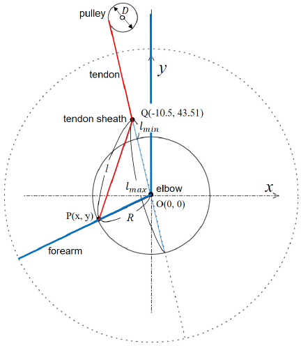
Fig. 10. Graph of elbow joint positions from a side view.
The amount of polyethylene line winding required to achieve the maximum range of motion of the elbow joint was derived as shown in Eqs. \(\eqref{eq:eqcircle}\) and \(\eqref{eq:eqpulley}\). Eq. \(\eqref{eq:eqcircle}\) represents the equation of a circle with radius \(R\) centered at origin O \((0, 0)\). Point P \((x, y)\) moves along this circumference. By determining the difference between the maximum and minimum distances between points P and Q, the amount of tendon winding necessary to enable the maximum range of the elbow joint can be calculated. Note that in this case, \(R\) was 35.63 mm.
The maximum distance \(l_{max}\) and minimum distance \(l_{min}\) between points P and Q were observed when points O, P, and Q were colinear. Calculating the distance PQ from the coordinates of points P and Q yielded a maximum distance \(l_{max}\) of 80.39 mm and a minimum distance \(l_{min}\) of 9.124 mm. Therefore, the minimum number of polyethylene line windings necessary to move the elbow joint from flexion to extension was the difference between the maximum and minimum distances, which was 71.26 mm.
In this study, the servo motors used had a maximum range of motion of 270°, as listed in Table 2. The length of the polyethylene line wound by the pulley is given by Eq. \(\eqref{eq:eqpulley}\), which indicates that the pulley diameter must be approximately 30.24 mm.
Based on these considerations, a pulley with a diameter of approximately 35 mm was selected for the servo motor for flexion and extension. Using the same calculation process, a pulley with a diameter of approximately 25 mm was adopted for the servo motor used for pronation and supination.
4.3. Tendon
Polyethylene lines were used as the element serving the role of tendons in tendon-driven actuation. This choice was based on a study by Xu et al. 18, who developed a robotic hand that precisely replicated human bone and ligament structures, achieving human-like movements through tendon-driven mechanisms.
In the robotic hand developed by Xu et al., polyethylene threads were employed as ligaments and tendons owing to their strength, stiffness, flexibility, and low-friction properties, which enabled smooth motion. Based on these considerations, this study adopted polyethylene lines as tendons.
4.4. Bearings
The elbow joint was constrained by bolt fastening, whereas the interior of the ulna served as a simple bearing holder containing a bearing that fit the bolt diameter. Additionally, ball joints are employed at both the proximal radioulnar joint and distal radioulnar joint, which are responsible for forearm pronation and supination, respectively, thereby facilitating smooth movements of the elbow joint and the two radioulnar joints.
4.5. Implementation of Potentiometer
The range of motion and current position of each movement were measured using a potentiometer. Unlike encoders, potentiometers do not require homing or self-position estimation after the power is turned off, and can recognize angles with a certain level of accuracy, which is why they have been adopted. Their purpose was to detect joint angles, aiding in measuring the range of motion during physical evaluations, as well as in feedback control. The specifications of the potentiometers are listed in Table 3.
Table 3. Specifications of the potentiometer JC10.

5. Evaluation of Designed Frame Model
Based on the previous section, we evaluated the frame model from a functional perspective. The evaluation primarily focused on the range of motion, given that features such as the offset of the elbow joint and the curvature of the ulna and radius are expected to enhance the range of motion.
5.1. The Method for Evaluating the Frame Model
This section describes the evaluation method of the designed frame model. The evaluation focused on the range of motion and assessed the effects of bone curvature and joint offsets on the range of motion. To evaluate the range of motion, comparative frame models were created using 3D CAD, and their ranges were compared based on the presence or absence of these structural features. The angle measurement functions in 3D CAD were employed to compare the ranges of motion using the three frame models shown in Fig. 11. Fig. 11(a) shows the frame model depicted in Fig. 7. Fig. 11(b) shows a structure in which the elbow joint is not offset, meaning that the center of rotation for flexion and extension of the elbow is aligned with the long axis of both the humerus and ulna. Fig. 11(c) shows a structure in which the radius and ulna are not curved.
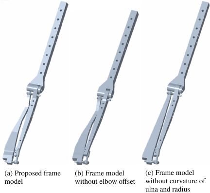
Fig. 11. The three models used for evaluation.
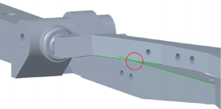
Fig. 12. Evaluation of the range of motion.
The range of motion for elbow flexion/extension, as well as for forearm pronation and supination, was based on the specifications of the robot arm listed in Table 1. With the neutral position set at 0°, and with flexion as positive, the maximum flexion is 145° and the maximum extension is \(-5\)°. For forearm pronation/supination, with the neutral position at 0°, the maximum pronation is \(-85\)° and the maximum supination is 90°, with supination as positive. As previously mentioned, range of motion is restricted by the bones, muscles, and ligaments to prevent exceeding the functional range. In this evaluation, the absence of muscle constraints indicated that exceeding the range of motion was not an issue. The specific measurement method involved simulation of a 3D CAD model. The limits of the range of motion for each movement were determined by the positions at which the skeletal components came into contact with each other, as shown in Fig. 12, and the range was measured by extracting these angles.
5.2. Result of the Evaluation of Frame Model
The results of the range of motion comparison based on the three frame models presented in the previous section are listed in Table 4. It displays angles for four limb positions, maximum flexion, maximum extension, maximum pronation, and maximum supination, when the neutral position is set at 0°. For the elbow, the direction of flexion was considered positive; for the forearm, the direction of supination was considered positive.
In model (a), the range of motion for flexion, extension, pronation, and supination met the design requirements.
Model (b) satisfied the design requirements for two positions, maximum pronation and maximum supination, similar to model (a). However, for maximum flexion, it fell short by approximately 47°, reaching only 102.5°.
Table 4. Summary of the range of motion in three models.

Model (c) meets the design requirements for maximum flexion and maximum extension, similar to model (a); however for maximum pronation, it deviates by 3.400° towards supination from the neutral position. In other words, there was a deficiency in the range of motion for pronation.
Additionally, Table 4 lists the range of motion of the upper limb of the tendon-driven humanoid robot “Kengoro” developed by Kawaharazuka et al. 6. While flexion, pronation, and supination satisfied the human range of motion, it was observed that in maximum extension, there was a shortfall of 5°.
As a supplement, Fig. 13 shows the range of motion for the flexion and extension of model (a) and model (b) within a single diagram, indicating that the flexion range of model (b) does not meet the design requirements. Fig. 14 shows the range of motion for pronation and supination of model (a) and model (c) within a single diagram, indicating that the pronation range of model (c) does not satisfy the design requirements.
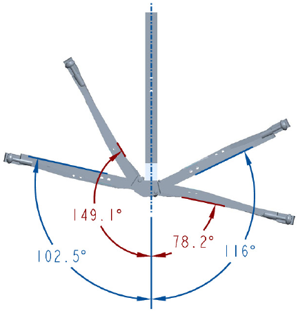
Fig. 13. Comparison between model (a) versus model (b).
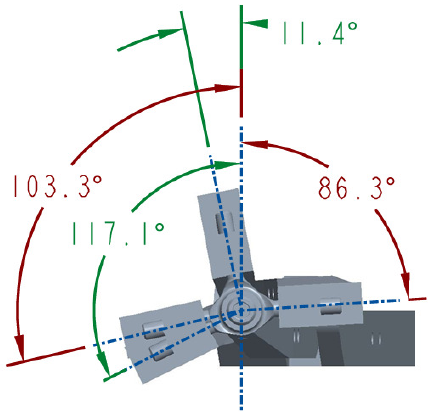
Fig. 14. Comparison between model (a) versus model (c).
5.3. Discussion of Evaluation of the Frame Model
Based on the results discussed in the previous section, this section examines the characteristics and range of motion of the models. By incorporating joint offsets and bone curvature, which are part of the human structure, an expanded range of motion was achieved compared with models without these features. From the results of the maximum pronation and maximum supination for models (a) and (c) listed in Table 4, the offset of the joint can be said to reduce the range of motion for extension, while increasing the range of motion for flexion. Similarly, bone curvature reduces the range of motion for supination and increases the range of motion for pronation. Even if the radius and ulna are made thinner, their respective ranges of motion can be expanded; however, a model incorporating the human structure would still result in a greater overall range of motion. Furthermore, the insufficient extension range of motion in the tendon-driven humanoid robot “Kengoro” developed by Kawaharazuka et al. 6 is considered to be due to a lack of space behind the elbow joint. This limitation is thought to increase the risk of elbow joint damage caused by collisions between the skeletal components during extension. Thus, the incorporation of human anatomical structures effectively enhances the functionality of the robot arm.
6. Operational Experiments Using the Prototype
To verify the operation of the fabricated robotic arm, operational tests were conducted to confirm whether basic movements were possible. The purpose of this study was to verify whether basic movements could be achieved in a robot arm that incorporated a human structure. The operations performed in this study included elbow flexion and extension and forearm pronation and supination. Note that the robot arm prototype developed in this study did not include a hand; therefore, more specific actions such as writing or tool usage were not performed.
6.1. The Method for Operational Experiments Using the Prototype
In the operational experiments, the prototype was fixed to a base, and elbow flexion and extension, as well as forearm pronation and supination, were performed by coordinating variable resistors with servo motors. A potentiometer was used to measure the range of motion of the joints.
To control the prototype, an Arduino was used as the microcontroller, and the servo motors were operated via serial communication. A variable resistor, commonly used in electronic prototyping, was employed, and its output values were converted through an analog-to-digital conversion into the servo motor’s range of motion, enabling the servo motors to be controlled by the variable resistor.
In elbow flexion and extension as well as forearm pronation and supination, the amount of rotation of the two antagonistic servo motors differs for each movement. Therefore, for the two polyethylene lines to remain under tension during operation, it is necessary to determine the amount of rotation of each servo motor in advance. To achieve this, a method was implemented wherein the command values were calculated based on the relationship between their current positions. A command was issued to only one of the servo motors, and the other servo motor was passively moved. By recording the current values of the servo motors when both polyethylene lines were tensioned and repeating this process up to the movement limits, the relationship between the command values of the two servo motors was plotted as a graph.
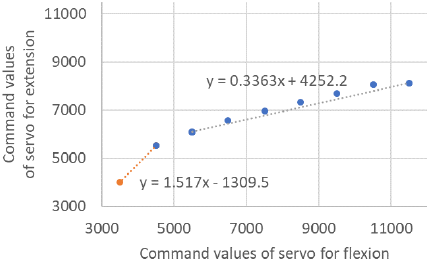
Fig. 15. The relationship between the command values of the two servo motors performing flexion and extension.
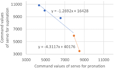
Fig. 16. The relationship between the command values of the two servo motors performing pronation and supination.
The graphs obtained using this process are shown in Figs. 15 and 16. Fig. 15 shows the relationship between the command values of the two servo motors during flexion and extension, whereas Fig. 16 shows the relationship during pronation and supination. Figs. 15 and 16 show that two approximation formulas are derived for each movement. This is owing to the interference of the skeleton and polyethylene lines during operation, and this characteristic is an advantage of this method. Even when the number of polyethylene line windings differs according to the shape of the skeleton, this method can derive approximation formulas suited to that particular geometry, thereby allowing the system to accommodate changes in winding caused by interference between the skeleton and tendons.
Based on the equations describing the relationship between the command values of the two servo motors derived using this method, control was performed by sending command values to each servo motor for flexion/extension and pronation/supination, according to the output values of the variable resistor.
A potentiometer was used to measure joint angles. Next, a method for measuring joint range of motion using a potentiometer is described.
Specifically, at the center of rotation of each joint, a gear is fixed in place so that it does not rotate during the operation. This fixed gear meshes with a gear attached to the potentiometer shaft. As the joint operates, the gear on the potentiometer shaft rotates while moving around the rotation center; therefore, the rotation angle of the joint can be determined from the arc length traced by the contact point of the gears. Eq. \(\eqref{eq:eqpot1}\) shows the formula used to derive the angular displacement \(\theta_1\) [°] of the potentiometer based on the change in its output analog value \(\Delta A\). Using \(\theta_1\), Eq. \(\eqref{eq:eqpot2}\) derives the angular displacement \(\theta_2\) [°] of the joint.
The effective electrical angle of the potentiometer used was 324°, and \(D_1\) denotes the reference pitch diameter of the gear fixed to the potentiometer shaft, whereas \(D_2\) denotes the reference pitch diameter of the gear fixed to the joint’s center of rotation. The ratio of the reference pitch diameters of the gear fixed to the rotation center and the gear fixed to the potentiometer shaft, that is, the gear ratio, affects the calculation of the arc length. Using these equations to derive the angular displacement of the joint, the ranges of motion for flexion/extension and pronation/supination were determined.
Table 5. Range of motion of each joint in the operational experiments.

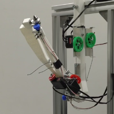
Fig. 17. Elbow flexion of the prototype.
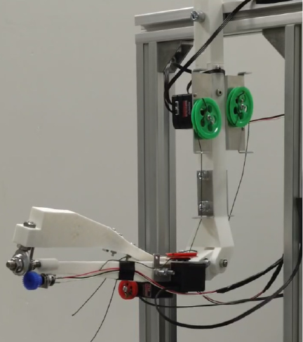
Fig. 18. Forearm pronation of the prototype.
6.2. Result of the Operational Experiments
In this section, the results of operational experiments using the prototype are described. Table 5 lists the ranges of motion achieved for each movement. Fig. 17 shows the flexion of the elbow, and Fig. 18 shows the pronation of the forearm.
Table 5 shows that a range of motion equivalent to or greater than that of a human was achieved in all limb positions. All movements were performed and a smooth operation was realized in elbow flexion and extension. However, in forearm pronation and supination, the movement was not smooth. Specifically, the motion speed was unstable between the pronated and neutral positions.
6.3. Discussion of the Operational Experiments
Based on the previous section, this section discusses the results of operational experiments using the prototype. The prototype was able to achieve basic movements of elbow flexion and extension, as well as forearm pronation and supination. Moreover, in all limb positions, the design requirement for achieving the human range of motion was satisfied. From this, it can be said that the robot arm incorporating structures such as the elbow joint offset, and the curvature of the ulna and radius, was able to function adequately.
However, during forearm pronation and supination, the movement speed was unstable between the fully pronated and neutral positions. Several factors may be involved; however, the primary cause is considered to be the positional relationship between the pulley of the servo motor contributing to pronation and the attachment point of the polyethylene line to the radius. In the maximum pronated position, the radius crosses over the ulna. At that time, because the pulley pulling the radius was located below the radius, sufficient tension was not applied for the radius to rotate to a neutral position, and the motion did not start until the tension increased to the level required for rotation. This is believed to have caused the inconsistent motion speed.
It is possible to stabilize the motion by changing the direction of tension to make it easier to rotate the radius. It is inferred that adding relay components that act as tendon sheaths can mitigate this problem. Additionally, the elastic force generated by the polyethylene line itself was considered to have an influence, and it is possible that the motions of the two antagonistic servo motors responsible for pronation and supination were not fully synchronized. Therefore, it is expected that improvements can be achieved by applying corrections to the command values of servo motors.
7. Conclusion
This study aims to develop a tendon-driven humanoid robot that incorporates human anatomical structures, focusing on the development of a robotic arm from the upper arm to the forearm. Skeletal structure was examined to achieve this goal. The human anatomical structures and their functions were explained, providing an overview of the robot arm being developed and describing the actual frame model of the robot arm created. The evaluation of the designed frame model revealed its effectiveness in terms of the range of motion. By incorporating joint offsets and bone curvature, as found in the human anatomy, an expanded range of motion was achieved compared with a structure without these features.
Considering that the workspace is in front of and medial to the body, the expansion of the range of motion in flexion and pronation can be said to contribute to improved functionality. Furthermore, based on both the 3D CAD and prototype results, the range of motion of the human upper limb was satisfactory. Although pronation and supination movements did not result in a fully smooth operation, the prototype was able to achieve the basic movements of elbow flexion and extension, forearm pronation, and supination.
Based on these results, the robot arm structure proposed in this study can be said to be advantageous in terms of range of motion. However, further investigation is necessary regarding the other advantages and disadvantages of these structures, as well as methods for implementing them in actual robots.
In future work, we will evaluate the effectiveness of incorporating ligaments, tendon sheaths, and interosseous membranes as well as the number and arrangement of muscles, which were not considered in this study. Ligaments are expected to suppress joint damage owing to their flexibility when forces are applied in directions different from the axis of joint rotation. Tendon sheaths serve as pathways for tendons and play a role in adjusting the direction of tension generated by the tendons, facilitating their smooth movement. Therefore, they are expected to improve the efficiency of tendon-driven mechanisms. The effectiveness of the ligaments and tendon sheaths can be evaluated by comparing cases with and without implementation in the robot arm. If effects such as the suppression of skeletal damage or reduction of torque transmission losses are observed, it can be said that these structures are effective. In this study, the effectiveness of several structures was demonstrated by evaluating their range of motion. However, it is also necessary to evaluate and discuss the impact of these structures on the strength, kinematics, and practical applicability.
- [1] Ministry of Land, Infrastructure, Transport and Tourism (MLIT), “Regarding the recent situation surrounding the construction industry,” (in Japanese). https://www.mlit.go.jp/policy/shingikai/content/001428484.pdf [Accessed December 18, 2023]
- [2] I. Mizuuchi, “Organization and Design of Biologically-Inspired Musculoskeletal Humanoids,” J. of the Robotics Society of Japan, Vol.28, No.6, pp. 689-694, 2010 (in Japanese). https://doi.org/10.7210/jrsj.28.689
- [3] H. Song, Y.-S. Kim, J. Yoon, S.-H. Yun, J. Seo, and Y.-J. Kim, “Development of Low-Inertia High-Stiffness Manipulator LIMS2 for High-Speed Manipulation of Foldable Objects,” Int. Conf. on Intelligent Robots and Systems (IROS), pp. 4145-4151, 2018. https://doi.org/10.1109/IROS.2018.8594005
- [4] A. Ke, J. Huang, and J. He, “An Underactuated Prosthetic Hand with Coupled Metacarpophalangeal Joints,” J. Adv. Comput. Intell. Intell. Inform., Vol.22, No.5, pp. 674-682, 2018. https://doi.org/10.20965/jaciii.2018.p0674
- [5] W. Yu, D. Nishikawa, Y. Ishikawa, H. Yokoi, and Y. Kawazu, “Multifunctional Electrical Prosthetic Hand – Development of Tendon-driven Mechanism and Controller –,” J. Robot. Mechatron., Vol.14, No.6, pp. 557-564, 2002. https://doi.org/10.20965/jrm.2002.p0557
- [6] K. Kawaharazuka, S. Makino, M. Kawamura, S. Nakashima, Y. Asano, K. Okada, and M. Inaba, “Human Mimetic Forearm and Hand Design with a Radioulnar Joint and Flexible Machined Spring Finger for Human Skillful Motions,” J. Robot. Mechatron., Vol.32, No.2, pp. 445-458, 2020. https://doi.org/10.20965/jrm.2020.p0445
- [7] Y. Asano, T. Kozuki, S. Ookubo, M. Kawamura, S. Nakashima, T. Katayama, I. Yanokura, T. Hirose, K. Kawaharazuka, S. Makino, Y. Kakiuchi, K. Okada, and M. Inaba, “Human Mimetic Musculoskeletal Humanoid Kengoro toward Real World Physically Interactive Actions,” Int. Conf. on Humanoid Robots (Humanoids), pp. 876-883, 2016. https://doi.org/10.1109/HUMANOIDS.2016.7803376
- [8] M. Raibert, K. Blankespoor, G. Nelson, R. Playter, and the BigDog Team, “BigDog, the Rough-Terrain Quadruped Robot,” Proc. of the 17th World Congress: The Int. Federation of Automatic Control, pp. 10822-10825, 2008. https://doi.org/10.3182/20080706-5-KR-1001.01833
- [9] A. I. Kapandji, “Anatomie Fonctionnelle,” pp. 90-145, Vigot-Maloine, 2019.
- [10] A. Al-Ibadi, S. Nefti-Meziani, and S. Davis, “A Robot Continuum Arm Inspired by the Human Upper Limb: The Pronation and Supination Rotating Behaviour,” Proc. of the 2nd Int. Conf. on Electrical, Communication, and Computer Engineering (ICECCE), 2020. https://doi.org/10.1109/ICECCE49384.2020.9179338
- [11] P. E. Sandin, “Robot Mechanisms And Mechanical Devices Illustrated,” p. 245, McGraw Hill, 2003.
- [12] B. M. Gammon, “Arthrokinematics of the Distal Radioulnar Joint in the Normal Wrist and Following Distal Radius Malunion,” Electronic Thesis and Dissertation Repository, pp. 1-36, 2016.
- [13] R. P. van Riet, F. Van Glabbeek, P. G. Neale, R. Bimmel, H. Bortier, B. F. Morrey, S. W. O’Driscoll, and K. N. An, “Anatomical Considerations of the Radius,” Clinical Anatomy, Vol.17, No.7, pp. 564-569, 2004. https://doi.org/10.1002/ca.10256
- [14] M. A. Khan, H. Gul, and S. M. Nizami, “Determination of Gender from Various Measurements of the Humerus,” Cureus, Vol.12, No.1, Article No.e6598, 2020. https://doi.org/10.7759/cureus.6598
- [15] J. R. Brownhill, G. J. W. King, and J. A. Johnson, “Morphologic analysis of the distal humerus with special interest in elbow implant sizing and alignment,” J. of Shoulder and Elbow Surgery, Vol.16, No.3, Supplement, pp. S126-S132, 2007. https://doi.org/10.1016/j.jse.2006.01.018
- [16] A. Adikrishna, J. Y. Kim, A. L. Kekatpure, H.-J. Lee, M. Kim, and I.-H. Jeon, “Dorsal apex curve of the proximal ulna,” Acta Orthopaedica et Traumatologica Turcica, Vol.50, No.1, pp. 97-102, 2016. https://doi.org/10.3944/AOTT.2016.15.0146
- [17] D. Polimanti and G. Giannicola, “Anatomy of the Elbow and How It Affects Implant Design,” F. Castoldi, G. Giannicola, and R. Rotini (Eds.), “Elbow Arthroplasty,” pp. 23-36, 2020. https://doi.org/10.1007/978-3-030-14455-5_3
- [18] Z. Xu, “Design and Control of an Anthropomorphic Robotic Hand: Learning Advantages From the Human Body & Brain,” 2015.
This article is published under a Creative Commons Attribution-NoDerivatives 4.0 Internationa License.