
Research Paper:
Component Influence-Driven Fastener Reduction for Robotic Disassemblability-Aware Design Simplification
Takuya Kiyokawa*,†
 , Tomoki Ishikura**
, Shingo Hamada**, Genichiro Matsuda**
, and Kensuke Harada*
*Department of Systems Innovation, Graduate School of Engineering Science, The University of Osaka
1-3 Machikaneyama, Toyonaka, Osaka 560-8531, Japan
†Corresponding author
**Manufacturing Innovation Division, Panasonic Holdings Corporation
Kadoma, Japan

Robotic disassembly must be considered during the product design phase to accelerate automated remanufacturing. However, designers currently lack quantitative feedback for identifying the structural elements that hinder robotic operations. To address this, this study proposes an analytical framework that provides actionable redesign guidance focused on fastener reduction, because fasteners are numerous and ubiquitous components found in almost all manufactured products. Using a computer-aided design (CAD) model and its automatically generated contact-connection-constraint (CCC) graph, the framework translates the robotic disassembly sequence planning outcomes into component influence scores. These scores reflect the frequency with which a component causes structural constraint violations or evaluation objective deteriorations in a robotic disassembly sequence. To visually highlight structural hindrances, the framework projects these scores onto the CAD geometry as 3D heatmaps. The system then analytically simulates the removal of highly influential fasteners. It reports the expected reductions in structural constraints, tool changes, and robot travel distances while preventing structurally unsafe modifications by evaluating geometric stability metrics. Experiments on seven household appliances demonstrated that the framework successfully targeted redundant fasteners. Removing the recommended fasteners simplified the structural dependencies by eliminating 8–132 structural constraints on the graph depending on the structural configuration of each product. Furthermore, it improved the robotic operational efficiency by eliminating unnecessary tool change operations and shortening travel distances by 165–1675 mm wherever it was structurally permissible.
1. Introduction
The robotics-based automation of remanufacturing processes is important for advancing sustainable manufacturing 1,2 and is further motivated by the goal of shortening lead times and improving working conditions 3,4. To automate end-of-life consumer products, quantitative disassembly feedback is required during the mechanical design process 5,6.
Existing design for disassembly approaches address manual dismantling efforts, structural complexity, and computer-aided design (CAD)-based geometric modifications for semi-destructive processing 7,8. Extending this line of research, studies on the design of automatic disassembly have examined the product features that facilitate automated disassembly, including accessibility, nondestructive separation, and standardized fasteners and tools 9,10. However, evaluations of operational difficulties 11,12 in robotic manipulation rarely lead to concrete product redesign guidelines.
This study was based on the hypothesis that removing components with high influence scores from a robotic disassembly sequence reduces sequence constraints and improves operational efficiency. Based on this premise, this paper proposes an analytical framework that translates the position of a part within a feasible robotic disassembly sequence into a per-part influencing score. The system calculates this score by counting the frequency at which a positional swap breaks structural constraints or degrades the evaluation objectives of the robotic disassembly sequence planner.
The proposed pipeline utilizes these scores to systematically reduce a highly actionable design parameter: the number of fasteners. Fasteners were targeted because they are common and readily modifiable design elements. Although screw-fastened parts are removable in principle, their removal can still be difficult for robots because a robot has limitations regarding where its tool can reach and from which directions it can approach a fastener. For example, some fasteners may not be reachable directly from the current product pose, whereas others may require product reorientation or long robot motions because the surrounding parts block the required approach direction. Therefore, the proposed framework ranks fasteners based on the robotic disassembly planning outcomes.
Given a CAD model and its corresponding contact-connection-constraint (CCC) graph 13, the system operates analytically without invoking generative models 14,15,16,17,18,19,20. By simulating the removal of high-influence fasteners and recounting the remaining graph constraints, it evaluates direct improvements in robotic operational efficiency, specifically the reduction of structural constraints, tool-change counts, and inter-part travel distances.
The primary contribution of this study is this analytical framework, which presents these evaluations as 3D influence heatmaps and a ranked reduction candidate list, which is sorted in descending order based on the influence scores. This auditable output allows designers to carefully balance geometric stability with robotic operational efficiency, aligned with the principles of design for remanufacturing 5,21 and design for robotic assembly (DfRA) 6. Finally, experiments on seven household appliances validate this approach, demonstrating how the extracted information serves as a practical, quantitative redesign guideline for fastener removal without exhaustive geometric modifications.
2. Related Works
To design products for robotic disassembly, engineers must consider robot-specific constraints, such as kinematic limits, rigid sequence dependencies (e.g., the requirement to remove a specific exterior cover before accessing target internal parts), and tool-change overheads, while also considering how product structure affects automated dismantling, as examined in earlier case studies 22,23. Consequently, recent research on design for robotic disassembly and consumer electronic redesign specifically targets the integration of these physical constraints into the mechanical design phase for automated operations 24,25. For example, iterative frameworks refine structures for physical feasibility 6.
Generative approaches leverage deep learning and large language models (LLMs) to explore conceptual designs and synthesize CAD geometries 14,15,16,17,18,19,20. Additionally, remanufacturing guidelines are derived from product information and lifecycle scenarios to support a circular economy 5. Although these advances provide abstract guidelines that lack specific geometric modification steps, there remains a need for quantitative metrics that link specific structural choices with both geometric stability and robotic operational efficiency.
On the operational execution side, recent advances have established robust methods for robotic disassembly sequence planning, task allocation, and motion scheduling under structural constraints 26,27,28,29,13. The maturity of these planning frameworks allows for a quantitative evaluation of robotic disassemblability. Rather than treating planning as the final step in adapting to a fixed product, these established technologies can serve as an analytical basis for evaluating the product design.
This study bridges the gap between execution-level planning and structural design evaluation. By applying the established sequence-and-motion planning capabilities, planning outcomes were translated into structured redesign feedback. The framework distinguishes itself by transforming sequence-derived influence metrics into concrete and per-fastener reduction recommendations ranked by their combined influence scores. This provides human engineers with influence heatmaps and ranked recommendations for improving robotic disassembly, linking geometric stability and robotic operational efficiency directly back to the mechanical design process.
3. Methods
3.1. System Overview
The proposed analytical framework evaluates product structures to generate redesign candidates for robotic disassembly. This process is summarized in Algorithm 1, which integrates three distinct phases into a single execution flow.
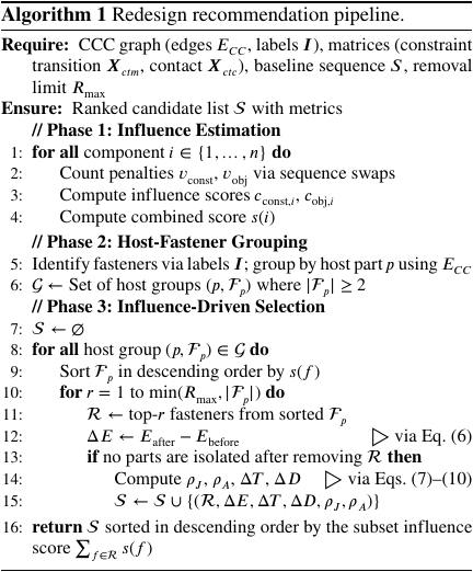
First, the system estimates the structural influence of each component by simulating the positional swaps in the baseline robotic disassembly sequence. Next, it utilizes a CCC graph (Fig. 1) to identify the host parts and enumerate feasible fastener-reduction candidates. Finally, the geometric stability and robotic operational efficiency impacts of each candidate were evaluated.
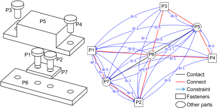
Fig. 1. Illustrative CCC graph structure for a seven-part example assembly. Circles and triangles represent part and fastener nodes, respectively. Black lines indicate contact edges, red lines indicate connection edges, and blue arrows represent constraint edges. \(\Delta E\) evaluates the reduction of these constraint edges.
3.2. Component Influence Estimation
To provide a quantitative basis for the redesign, the framework calculates influence scores representing the degree to which each part acts as a structural hindrance. Given a feasible baseline robotic disassembly sequence \(S\) of length \(n\) 13, the system evaluates each target component index \({i \in \{1, \dots, n\}}\). It generates \({n-1}\) modified sequences \(S_k\) by moving component \(i\) to every other position in \(S\).
The system counted the resulting structural constraint violations \(v_{\mathrm{const}}(S_k)\) and objective-value degradations \(v_{\mathrm{obj}}(S_k)\) for each swap sequence \(S_k\). This term \(v_{\mathrm{const}}\) aggregates disassembly feasibility and stability constraint violations 29,13. The term \(v_{\mathrm{obj}}\) aggregates the objective degradation of the planner evaluation. The constraint-violation score \(c_{\mathrm{const}, i}\) and the objective-degradation score \(c_{\mathrm{obj}, i}\) for component \(i\) are the averages over the \({n-1}\) swaps (Phase 1 of Algorithm 1):
3.3. Fastener Reduction Simulation
The framework identifies fastener-reduction candidates by analyzing the CCC graph. Components are identified as fasteners if their node labels \(\boldsymbol{I}\) include _screw, _bolt, or _nut. The system scans the graph edge set \(E_{CC}\) to group fasteners \(\mathcal{F}_p\) attached to the same host part \(p\) (Phase 2 of Algorithm 1). For each group, the system selects the \(r\) fasteners with the highest combined influence score \(s(f)\), where \(f\) represents the component index of the fastener, as defined in Eq. (3). This selection is repeated for each removal count \({r \in \{1, \dots, R_{\mathrm{max}}\}}\), where \(R_{\mathrm{max}}\) is the maximum limit. Let \(\mathcal{R}\) be a subset of the fasteners selected for removal.
To compute the reduction in structural constraints, a binary keep-mask \(m\) is applied to each part index. The mask sets \({m_{j} = 0}\) if part \({j \in \mathcal{R}}\), and \({m_{j} = 1}\) otherwise. The binary constraint indicator \(e_{ij}\) is derived from the constraint-transition matrix \(\boldsymbol{X}_{ctm}\). The logical OR operator (\(\lor\)) ensures that the indicator function \(\mathbb{I}\) evaluates to 1 if either part \(i\) physically blocks part \(j\), or part \(j\) blocks part \(i\) (Phase 3 of Algorithm 1):
3.4. Assessment of Redesign Impacts
Each candidate was evaluated for geometric stability and robotic operational efficiency. Stability was measured using two geometric stability metrics: polar moment ratio \(\rho_{J} = J_{\mathrm{after}}/J_{\mathrm{before}}\) and convex hull area ratio \(\rho_{A} = A_{\mathrm{after}}/A_{\mathrm{before}}\). \(J\) is the mean squared distance of the remaining fasteners from their geometric centers. Both quantities are defined using the individual center coordinates \(\boldsymbol{p}_f\) of the remaining fasteners; \(J\) additionally uses their arithmetic mean \(\boldsymbol{\bar{p}}\):
Operational efficiency gains are quantified by the reduction in tool changes \(\Delta T\) and robot travel distance \(\Delta D\). Let \(T\) be the count of changes in the assigned end-effector \(\mathrm{tool}_k\) for step \(k\), and let \(D\) be the sum of the distances between successive component positions \(\boldsymbol{p}\) in sequence \(S\):
4. Experiments
4.1. Setup
Seven household appliances were used as case studies (cs1–cs7): a condenser unit, television, outdoor air-conditioner, microwave oven, compact microwave oven, optical beauty device, and power tool. Fig. 2 shows a 3D model representation of each product. For each product, the proposed analytical framework performs the following steps: (i) construct the CCC graph, (ii) calculate the influence scores \(c_{\mathrm{const}}\) and \(c_{\mathrm{obj}}\) for each component, (iii) run the fastener-reduction simulation with \(R_{\mathrm{max}} = 3\), and (iv) evaluate the constraint-reduction, efficiency, and stability metrics (\(\Delta E\), \(\Delta T\), \(\Delta D\), \(\rho_J\), and \(\rho_A\)).

Fig. 2. The seven case-study products (cs1–cs7): condenser unit, television, air-conditioner outdoor unit, microwave oven, compact microwave oven, optical beauty device, and power tool.
The operational efficiency metrics \(\Delta T\) and \(\Delta D\) are computed analytically against the two robotic cells illustrated in Fig. 3: a large and a small dual-arm cell. Both utilize dual-arm robots equipped with multi-view vision sensors, linear and rotary stages to rotate target objects, and end-effector tool racks placed near each arm.
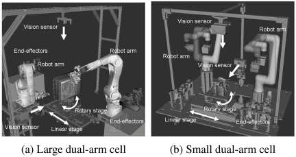
Fig. 3. The two robotic cells used to evaluate \(\Delta T\) and \(\Delta D\). Both utilize dual-arm robots equipped with multi-view vision sensors, linear and rotary stages to rotate target objects, and tool racks placed near each arm.
4.2. Influence Heatmaps
The framework projects the calculated influence scores onto a 3D geometry to visualize structural and operational hindrances. Figs. 4 and 5 show assembly-level heatmaps for \(c_{\mathrm{const}}\) and \(c_{\mathrm{obj}}\), respectively, across all seven products on a normalized \([0, 1]\) scale.

Fig. 4. Assembly-level \(c_{\mathrm{const}}\) heatmaps for the seven products. Darker colors denote high scores, indicating major structural constraints.

Fig. 5. Assembly-level \(c_{\mathrm{obj}}\) heatmaps for the seven products. Darker colors highlight components degrading operational efficiency.
The \(c_{\mathrm{const}}\) heatmaps (Fig. 4) highlight parts whose positions in the robotic disassembly sequence most frequently violate structural constraints. Base chassis parts, such as condenser unit side covers and television base plates, are consistently highlighted. This visually confirms that these base parts act as major structural constraints that lock the entire assembly together.
Conversely, the \(c_{\mathrm{obj}}\) heatmaps (Fig. 5) identify components that degrade the evaluation objectives of the planner. Components that violate the constraints often simultaneously increase \(c_{\mathrm{obj}}\) by disrupting the overall disassembly flow. Notably, \(c_{\mathrm{obj}}\) tends to be high across the exterior housing covers. This is because these large components necessitate extensive robot travel and frequent tool changes throughout the disassembly process. By providing both heatmaps, the framework allows engineers to diagnose whether a disassembly difficulty originates from a specific structural interference or broad operational inefficiency.
To turn these diagnostics into actionable instructions, the framework can also filter the heatmaps to color only the fasteners of the multi-fastened groups, rendering the remaining parts as a transparent scaffold. Figs. 6 and 7 show this directive view for \(c_{\mathrm{const}}\) and \(c_{\mathrm{obj}}\) for all seven products, respectively.

Fig. 6. Top-down directive view of \(c_{\mathrm{const}}\) identifying structurally critical fasteners clustered on upper faces.

Fig. 7. Top-down directive view of \(c_{\mathrm{obj}}\) identifying fasteners whose removal most improves efficiency.
4.3. Fastener Reduction Recommendations
Table 1 lists the top fastener-reduction candidates sorted by their influence scores. The reduction in structural constraints (\(\Delta E\)) ranges from 8 to 132 edges; cs6 attains the largest reduction magnitude \(-\Delta E\) because each fastener independently contributes to the structural constraints. The tool-change count (\(\Delta T\)) decreases by two on cs1. The travel distance (\(\Delta D\)) is shortened by 165 mm to 1675 mm.
| ID (product) | Strategy | \(\boldsymbol{\Delta E}\) | \(\boldsymbol{\Delta T}\) | \(\boldsymbol{\Delta D}\) [mm] | \(\boldsymbol{\rho_J}\) | \(\boldsymbol{\rho_A}\) |
| cs1 (condenser) | Random (20 trials) | \(-7{\pm}1\) | \(0.8{\pm}1.2\) | \(-854{\pm}585\) | 0.68 | 0.37 |
| Influence (proposed) | \(-9\) | \(-2\) | \(-1568\) | 1.06 | 0.00 | |
| cs2 (TV) | Random (20 trials) | \(-7{\pm}1\) | \(0.3{\pm}0.8\) | \(-984{\pm}740\) | 0.66 | 0.60 |
| Influence (proposed) | \(-9\) | \(0\) | \(-1675\) | 0.00 | 1.00 | |
| cs3 (AC unit) | Random (20 trials) | \(-7{\pm}1\) | \(0.1{\pm}0.6\) | \(-862{\pm}555\) | 0.64 | 0.50 |
| Influence (proposed) | \(-9\) | \(0\) | \(-1109\) | 1.07 | 0.45 | |
| cs4 (microwave) | Random (20 trials) | \(-7{\pm}1\) | \(0.1{\pm}0.4\) | \(-586{\pm}402\) | 0.67 | 0.64 |
| Influence (proposed) | \(-8\) | \(0\) | \(-462\) | 0.74 | 0.53 | |
| cs5 (compact MW) | Random (20 trials) | \(-7{\pm}1\) | \(0.2{\pm}0.6\) | \(-613{\pm}455\) | 0.64 | 0.65 |
| Influence (proposed) | \(-10\) | \(0\) | \(-1152\) | 0.00 | 1.00 | |
| cs6 (beauty device) | Random (20 trials) | \(-132{\pm}0\) | \(0.0{\pm}0.0\) | \(-151{\pm}40\) | 1.01 | 0.94 |
| Influence (proposed) | \(-132\) | \(0\) | \(-165\) | 1.10 | 1.00 | |
| cs7 (power tool) | Random (20 trials) | \(-40{\pm}6\) | \(0.5{\pm}0.9\) | \(-291{\pm}125\) | 0.94 | 0.67 |
| Influence (proposed) | \(-36\) | \(0\) | \(-585\) | 0.62 | 0.44 |
To quantify the value of using the influence score as a selection signal, the proposed component-influence rule was compared to a random baseline. This baseline draws \({r = 3}\) fasteners uniformly at random from each multi-fastened host group, averaged over 20 random trials. The proposed rule matches or exceeds the random baseline on \(\Delta E\) for six of the seven products; only on cs7 does random selection attain a slightly larger mean reduction magnitude \(-\Delta E\), as the host group admits several near-equivalent subsets of three fasteners. Tool-change savings (\(\Delta T\)) also favor the proposed rule: random selection raises \(\Delta T\) by an average of \(+0.3\), whereas the proposed rule strictly avoids increasing tool changes (\({\Delta T \leq 0}\)). It also yields larger travel-distance savings (\(\Delta D\)) on six of the seven products.
However, because high-influence fasteners tend to be spatially concentrated, the proposed rule returns more significant decreases in \(\rho_J\) or \(\rho_A\) than random selection.
4.4. Sensitivity to the Removal Limit \(R_{\textrm{max}}\)
Figure 8 plots the maximum possible \(\Delta E\), \(\Delta T\), and \(\Delta D\) as \(R_{\mathrm{max}}\) increases. \(\Delta E\) grows monotonically on every product. The marginal gain between \({R_{\mathrm{max}} = 3}\) and 4 is small, indicating that three fasteners is a practical cap. Furthermore, \(\Delta T\) saves only when an entire tool-operation run is removed (cs1), and \(\Delta D\) likewise saturates at \({R_{\mathrm{max}} = 3}\). \({R_{\mathrm{max}} = 3}\) is therefore adopted as the default limit.
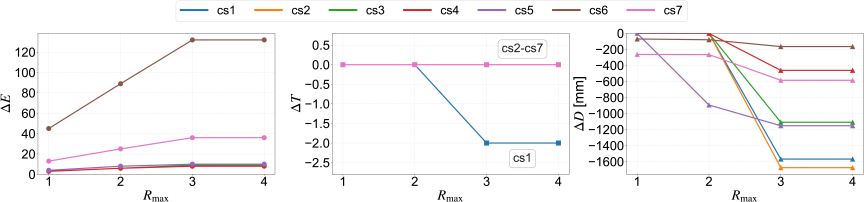
Fig. 8. Sensitivity of maximum possible \(\Delta E\), \(\Delta T\), and \(\Delta D\) to the limit \(R_{\mathrm{max}}\).
5. Discussion
5.1. Balancing Stability and Efficiency
This framework evaluates constraint-reduction, efficiency, and stability metrics (\(\Delta E\), \(\Delta T\), \(\Delta D\), \(\rho_J\), and \(\rho_A\)) to prevent structurally unsound modifications. Evaluating only \(\Delta E\), \(\Delta T\), and \(\Delta D\) could mislead designers into adopting structurally infeasible configurations. The geometric stability metrics (\(\rho_J\) and \(\rho_A\)) reveal the structural risks associated with each recommendation. Several products (cs1, cs2, and cs5) exhibited one ratio that collapsed to zero, indicating that the highest-influence fasteners were concentrated in a narrow linear region. Reporting both geometric stability metrics alongside \(\Delta E\) enables designers to reject recommendations in which the surviving fastener arrangement is no longer physically sound. Simultaneously assessing the geometric stability and robotic operational efficiency satisfies the structural requirements of robot-friendly design 6.
5.2. Generative Redesign Beyond Fastener Reduction
A consistent pattern across the products is that the base chassis parts often contain densely packed fasteners. These fasteners act as major structural constraints that complicate the robotic sequences. The top-down directive views (Figs. 6 and 7) filter the heatmaps to highlight only the fasteners in the multi-fastened groups. The \(c_{\mathrm{const}}\) view (Fig. 6) highlights the structurally critical fasteners on the top faces or outer perimeters, whereas the \(c_{\mathrm{obj}}\) view (Fig. 7) highlights fasteners whose removal improves the robotic operational efficiency. Together, these views identify where fastener reduction or connection redesign improves the robotic disassemblability.
Classical design for assembly methods reduce the part count by integrating parts that do not need to remain separate, thereby reducing the fasteners required to join them 30. In contrast, our method starts from an existing part structure and ranks individual fasteners according to their influence on the robotic disassembly planning. Therefore, the ranked candidates provide quantitative guidance on where part integration or connection redesign should be considered.
Designers can reduce and replace these connections by manually substituting multiple small fasteners with fewer robust joints or snap-fits. By leveraging recent advancements in multimodal LLMs and deep generative networks for CAD 15,16,20, this redesign process can be highly automated. Recent studies demonstrated that generative AI can synthesize complex 3D CAD geometries 14,17, generate CAD models of regularized mechanical components 19, and refine text-to-CAD models using visual feedback 18.
Future frameworks could feed the quantitative reduction metrics (\(\Delta E\), \(\Delta T\), and \(\Delta D\)) and geometric stability margins (\(\rho_J\) and \(\rho_A\)) extracted by our pipeline directly into these LLM-based CAD systems as spatial bounding constraints and semantic prompts. This integration enables generative models to automatically synthesize optimized, structurally sound joint structures or snap-fit alternatives exactly at the targeted structural constraints, thereby fully bridging the gap between analytical constraint identification and automated geometric redesign.
5.3. Physical Fidelity and Estimation Refinement
Constraint-reduction, efficiency, and stability metrics (\(\Delta E\), \(\Delta T\), \(\Delta D\), \(\rho_J\) and \(\rho_A\)) serve as practical indicators but do not account for material strength or robot dynamics. Future work will integrate finite-element analysis and motion planning while taking advantage of recent advancements in precise contact simulation technologies to provide a rigorous validation of cycle-time reductions. Despite the absence of dynamic robot simulations, the current CAD-based analysis effectively identifies and ranks the most critical fasteners for redesign. This demonstrates that structural hindrances can be quantified using geometric relationships alone, providing practical guidance without the need for complex physical modeling of robot motions.
6. Conclusion
This study presents an analytical framework that translates component-level influence scores into ranked fastener-reduction candidates for robotic-disassembly-aware redesign. The candidates are ranked based on their combined influence scores early in the design phase. The proposed pipeline reports changes in \(\Delta E\), \(\Delta T\), and \(\Delta D\), while evaluating geometric stability metrics (\(\rho_J\) and \(\rho_A\)) to prevent unsafe modifications.
Evaluations conducted on seven household appliances demonstrated that the generated recommendations eliminated between 8 and 132 structural constraints on the graph. Furthermore, they decrease the tool-change count by up to two and shorten the travel distance by 165 mm to 1675 mm. The experimental results further indicated that the maximum removal limits of the three fasteners were sufficient. In addition, this framework enables designers to identify systemic design patterns, thereby enabling the consolidation of redundant fasteners into robust joints early in the design phase.
Future research will focus on replacing these simplified geometric approximations with high-fidelity finite-element analyses validating efficiency metrics through integrated motion planning, and expanding the scope of design recommendations to include part translation, rotation, and snap-fit alternatives.
Acknowledgments
This study was supported by the New Energy and Industrial Technology Development Organization (NEDO) project JPNP23002.
- [1] H. Poschmann, H. Brüggemann, and D. Goldmann, “Disassembly 4.0: A review on using robotics in disassembly tasks as a way of automation,” Chem. Ing. Tech., Vol.92, No.4, pp. 341-359, 2020. https://doi.org/10.1002/cite.201900107
- [2] A. Ranjan Das and M. Koskinopoulou, “Toward sustainable manufacturing: A review on innovations in robotic assembly and disassembly,” IEEE Access, Vol.13, pp. 100149-100166, 2025. https://doi.org/10.1109/ACCESS.2025.3576441
- [3] E. Sundin et al., “Automation potential in the remanufacturing of electric and electronic equipment (EEE),” Adv. Transdiscipl. Eng., Vol.13, pp. 285-296, 2020. https://doi.org/10.3233/ATDE200166
- [4] M. Hochwallner, E. Sundin, and K. Johansen, “Automation in remanufacturing: Applying sealant on a car component,” Adv. Transdiscipl. Eng., Vol.21, pp. 147-158, 2022. https://doi.org/10.3233/ATDE220134
- [5] J. Xu et al., “A method for deriving remanufacturing design guidelines based on product information and life cycle scenarios,” T. Nonaka et al. (Eds.), “EcoDesign Accelerating Social Transformation: Vol. I,” pp. 83-102, Springer, 2026. https://doi.org/10.1007/978-981-95-9272-2_6
- [6] N. Khendry, C. Margadji, and S. W. Pattinson, “IDfRA: Self-verification for iterative design in robotic assembly,” 2026 IEEE Int. Conf. Robot. Autom. (ICRA), pp. 1831-1838, 2026. https://doi.org/10.1109/ICRA57385.2026.11697014
- [7] Y. Shiraishi, N. Miyaji, S. Fukushige, and Y. Umeda, “Proposal of a design method for dismantling products with split-lines,” Procedia CIRP, Vol.29, pp. 114-119, 2015. https://doi.org/10.1016/j.procir.2015.02.182
- [8] S. Fukushige, Y. Shiraishi, and Y. Umeda, “Computer-aided design for semi-destructive disassembly,” M. Matsumoto, K. Masui, S. Fukushige, and S. Kondoh (Eds.), “Sustainability Through Innovation in Product Life Cycle Design,” pp. 47-59, 2017. https://doi.org/10.1007/978-981-10-0471-1_4
- [9] E. Sundin, K. Elo, and H. M. Lee, “Design for automatic end-of-life processes,” Assem. Autom., Vol.32, No.4, pp. 389-398, 2012. https://doi.org/10.1108/01445151211262447
- [10] S. Shahbazi, K. Johansen, and E. Sundin, “Product design for automated remanufacturing—A case study of electric and electronic equipment in Sweden,” Sustainability, Vol.13, No.16, Article No.9039, 2021. https://doi.org/10.3390/su13169039
- [11] W. Vega-Brown and N. Roy, “Task and motion planning is PSPACE-complete,” Proc. AAAI Conf. Artif. Intell., Vol.34, No.6, pp. 10385-10392, 2020. https://doi.org/10.1609/aaai.v34i06.6607
- [12] T. Kiyokawa et al., “Difficulty and complexity definitions for assembly task allocation and assignment in human–robot collaborations: A review,” Robot. Comput.-Integr. Manuf., Vol.84, Article No.102598, 2023. https://doi.org/10.1016/j.rcim.2023.102598
- [13] T. Kiyokawa, T. Ishikura, S. Hamada, G. Matsuda, and K. Harada, “Hierarchical planning and scheduling for reconfigurable multi-robot disassembly systems under structural constraints,” 2026 IEEE/SICE Int. Symp. Syst. Integr. (SII), pp. 233-238, 2026. https://doi.org/10.1109/SII64115.2026.11404535
- [14] R. Wu, C. Xiao, and C. Zheng, “DeepCAD: A deep generative network for computer-aided design models,” 2021 IEEE/CVF Int. Conf. Comput. Vis. (ICCV), pp. 6752-6762, 2021. https://doi.org/10.1109/ICCV48922.2021.00670
- [15] L. Regenwetter, A. H. Nobari, and F. Ahmed, “Deep generative models in engineering design: A review,” J. Mech. Des., Vol.144, No.7, Article No.071704, 2022. https://doi.org/10.1115/1.4053859
- [16] K. Ma, D. Grandi, C. McComb, and K. Goucher-Lambert, “Conceptual design generation using large language models,” Proc. ASME 2023 Int. Des. Eng. Tech. Conf. Comput. Inf. Eng. Conf., Article No.V006T06A021, 2023. https://doi.org/10.1115/DETC2023-116838
- [17] X. Li, Y. Sun, and Z. Sha, “LLM4CAD: Multimodal large language models for three-dimensional computer-aided design generation,” J. Comput. Inf. Sci. Eng., Vol.25, No.2, Article No.021005, 2025. https://doi.org/10.1115/1.4067085
- [18] R. Wang, Y. Yuan, S. Sun, and J. Bian, “Text-to-CAD generation through infusing visual feedback in large language models,” Proc. 42nd Int. Conf. Mach. Learn. (ICML), pp. 65326-65345, 2025.
- [19] S. Kim, C. Lee, and J. Park, “A novel LLM-assisted approach for automated mechanical design of regularized geometries in CAD system,” IEEE Access, Vol.14, pp. 28840-28851, 2026. https://doi.org/10.1109/ACCESS.2026.3666652
- [20] L. Zhang, B. Le, N. Akhtar, S.-K. Lam, and D. Ngo, “Large language models for computer-aided design: A survey,” ACM Comput. Surv., Vol.58, No.9, Article No.225, 2026. https://doi.org/10.1145/3787499
- [21] O. Okorie, Y. Singh, J. Russell, C. Turner, and K. Oturu, “More than 10 years on: Does a state-of-the-art review and synthesis offer new frameworks to guide future design for remanufacturing research?,” Bus. Strateg. Environ., Vol.35, No.4, pp. 5194-5235, 2026. https://doi.org/10.1002/bse.70416
- [22] S. Kernbaum, C. Franke, and G. Seliger, “Flat screen monitor disassembly and testing for remanufacturing,” Int. J. Sustain. Manuf., Vol.1, No.3, pp. 347-360, 2009. https://doi.org/10.1504/IJSM.2009.023979
- [23] K. Elo and E. Sundin, “Process concepts for semi-automatic dismantling of LCD televisions,” Procedia CIRP, Vol.23, pp. 270-275, 2014. https://doi.org/10.1016/j.procir.2014.10.104
- [24] L. M. Ricard et al., “Design for robotic disassembly,” Proc. Des. Soc., Vol.4, pp. 2715-2724, 2024. https://doi.org/10.1017/pds.2024.274
- [25] M. Akkawi et al., “Consumer electronic redesign for automated disassembly using general-purpose robots,” Proc. Des. Soc., Vol.5, pp. 1031-1040, 2025. https://doi.org/10.1017/pds.2025.10117
- [26] Y. Laili, X. Li, Y. Wang, L. Ren, and X. Wang, “Robotic disassembly sequence planning with backup actions,” IEEE Trans. Autom. Sci. Eng., Vol.19, No.3, pp. 2095-2107, 2022. https://doi.org/10.1109/TASE.2021.3072663
- [27] K. Wang, L. Gao, X. Li, and P. Li, “Energy-efficient robotic parallel disassembly sequence planning for end-of-life products,” IEEE Trans. Autom. Sci. Eng., Vol.19, No.2, pp. 1277-1285, 2022. https://doi.org/10.1109/TASE.2021.3061506
- [28] X. Cui et al., “Discrete whale optimization algorithm for disassembly line balancing with carbon emission constraint,” IEEE Robot. Autom. Lett., Vol.8, No.5, pp. 3055-3061, 2023. https://doi.org/10.1109/LRA.2023.3241752
- [29] T. Kiyokawa et al., “Many-objective-optimized semi-automated robotic disassembly sequences,” Robot. Auton. Syst., Vol.197, Article No.105301, 2026. https://doi.org/10.1016/j.robot.2025.105301
- [30] G. Boothroyd and L. Alting, “Design for assembly and disassembly,” CIRP Ann., Vol.41, No.2, pp. 625-636, 1992. https://doi.org/10.1016/S0007-8506(07)63249-1
This article is published under a Creative Commons Attribution-NoDerivatives 4.0 Internationa License.