
Research Paper:
Automatic Control System for Mass Production Using Press Forming
Masayuki Aoyama*1, Masato Nagao*2, Ryuzo Mori*2, Minoru Yamashita*3,†, Kohei Furuya*3, Kazuhiro Mitamura*4, and Zhigang Wang*3
*1Tokai Rika Smart Craft Co., Ltd.
3-260 Toyota, Oguchi, Niwa-gun, Aichi 480-0195, Japan
*2Tokai Rika Co., Ltd.
Oguchi, Japan
*3Department of Mechanical Engineering, Gifu University
Gifu, Japan
†Corresponding author
*4Center for Advanced Die Engineering and Technology, Gifu University
Gifu, Japan

In various manufacturing processes, feedback control systems have been investigated to enhance productivity. However, applications in practical mass production are still limited. This study aimed to develop a closed-loop feedback system involving a new die set for nonstop mass production using a transfer press machine and to demonstrate its effectiveness in the real production of millions of pieces. Displacement and load sensors were embedded in the die set to monitor the product dimension and status of the upsetting punch. An actuator was also installed to adjust the product dimension controlled by threshold-type discrete feedback. Complex wiring from the sensors and their power sources were replaced with dedicated wireless data and power transmission devices to improve the mountability and operability when changing the die set. In the demonstration tests, the product thickness was precisely adjusted to 0.016 mm using the actuator controlled with a feedback command of 0.02 mm. The proposed system has been successfully used for the production of more than 6.5 million pieces during the period from the middle of 2023 to the end of 2025, demonstrating good durability and practicality. To detect a partial punch fracture, the Mahalanobis method is effective even when the fracture area is relatively small. To apply this method when a step-like change in the Mahalanobis distance is inevitable owing to interruptions according to the production schedule, the training data of the first several hundreds of shots need to be used for the production schedules.
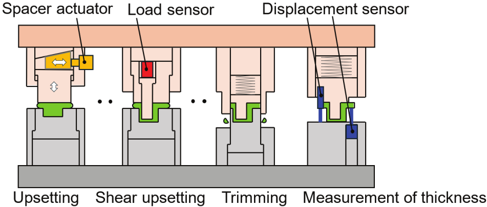
Press die set with measurement and feedback components
1. Introduction
An automatic adjusting system in manufacturing processes with feedback control is effective for achieving nonstop production for decreasing the cost of products and ensuring that the product quality is within an allowable range. Closed-loop feedback control systems have been investigated for various types of machining and plastic forming processes. Feedforward control-predictive algorithms are also effective and have been investigated.
Studies on process monitoring and control strategies for milling, drilling, and broaching operations have been reviewed 1. Furthermore, a method for reducing machining errors in small machine tools was proposed. The deformation of the machine structure and components during cutting was monitored to compensate for tool position, and the effectiveness of the method was demonstrated using a small three-axis numerical control milling machine 2. Feedback control, feedforward scheduling, and path optimization schemes for cutting forces in machining have been reviewed 3.
Additionally, closed-loop feedback control systems have been proposed for metal formation 4. Feedback control is suitable for incremental forming and hammering using a simple-shaped forming tool, because the forming operation is repetitive and stepwise. The online closed-loop feedback control of the product geometry in the incremental forming process of sheet metal has been demonstrated 5. In sheet metal forming, process control experiments that adjust the blank holding force have been conducted using a forming simulator to demonstrate an optimal reference punch force trajectory 6. To reduce the occurrence of cracks, a blank holding force was applied iteratively using a piezo-actuator based on flange draw-in signals 7.
The control of the sheet metal stamping process and its effect on product quality were reviewed, including control strategies with active blank holding force systems and in-process sensor technologies to monitor the process variables 8. For deep-drawing sheet metal parts, feedback control based on optical draw-in measurements and the performance of the control algorithm have been validated 9.
A closed-loop feedback control system has been proposed to compensate for the alignment of the upper die to improve the quality of large products 10.
The sensor installation position in the press die affects the force measurement results 11. Using a sensor embedded in the forming tool, real-time monitoring was conducted to capture frictional variations during stamping 12. The developed control system was verified experimentally for tube hydroforming, in which both wrinkling and bursting were successfully eliminated 13. A real in-process control that incorporates microsensors embedded in a practical forming die has been demonstrated to achieve optimum/adaptive in-process control, reflecting the forming stage 14. A feedforward control system for the steel sheet bending process was examined. The process parameters of the regression model were updated during production based on the historical data of the production line 15. In backward extrusion, the concentration deviation of the product was predicted using the data of the punch force with a support vector regression algorithm 16.
The integration of measurement techniques plays an important role in optimizing manufacturing processes to decrease production costs and increase product quality. Recent sensor technologies for in-process monitoring have been reviewed for deployment in various metal-forming processes, including rolling, bending, stamping, and deep drawing 17. A data analytics approach was applied to avoid quality incidents in the cold-rolling process, revealing critical parameters 18. Furthermore, the effectiveness of artificial intelligence for the quality control of metal forming and defect detection was discussed 19.
In the continuous production of sheet metal forming, the statuses of tools and press machines vary constantly. Hence, the dimensions of the products inevitably fluctuate owing to changes in the material properties, the temperature of the forming tools, and press machine used. Therefore, in a conventional mass-production scenario, to control the product dimensions within the tolerances, operators must check the product dimensions at regular production intervals and halt production to adjust the die height or replace the spacers and forming tools. Fig. 1 shows an example of a conventional forming die set with multiple stages and a product with a flange and teeth.
In the practical mass-production process examined in this study, the product was formed using a transfer press with 20 stages including 10 idle stages. The flange thickness \(t\) was determined during the upsetting stage and inevitably varied because the tool dimensions changed with the temperature rise during forming. As shown in Fig. 2, a significant decreasing trend in the flange thickness was observed at the start of production. Production was often halted by the operator when changing the die height or adjustable spacer, as shown in Fig. 1(a). Halting occurred four times in 3,000 shots, reducing productivity, as shown in Fig. 2. Punch surface fracture during tooth formation by shear upsetting could only be detected during regular inspection by the operator, although it rarely occurred suddenly. However, the punch fracture was not large-scale, but rather occurred over a small area; consequently, it did not affect the peak load and was difficult to detect.
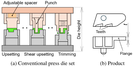
Fig. 1. Schematic of the forming process and product.
Feedback control systems have been developed in press forming; however, their applications in real-world mass-production scenarios are still limited. Such systems, which are suitable for mass production in press forming, should have good mountability of sensors and data transmission devices in the narrow space of the die set and provide easy operation when setting up the die set.
In this study, a feedback control system is developed, and its performance is verified through the mass production of the product, as illustrated in Fig. 1. In the proposed system, wireless power transmission and compact wireless data transmission systems were used to provide good mountability and operability of the improved die set. A detection method for small-scale tool fractures was also investigated through punch force monitoring using a wireless data transmission system and statistical calculations.
The contributions of this study are as follows: (i) the integration of sensors and an actuator into a mass-production press die set, enabling the feedback control of product dimensions and the detection of small tool fractures; (ii) the introduction of wireless data and power transmission to ensure good die-set operability; and (iii) the demonstration of excellent system durability and practicality through the long-term production of more than 6.5 million pieces. These points distinguish the present study from previous ones that primarily focused on laboratory-scale control and limited production demonstrations.
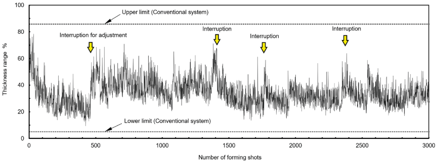
Fig. 2. Thickness change and manual interruption during production using a conventional production system.
2. Design of the Proposed System
2.1. Basic Configuration
The concept of the proposed press die set is illustrated in Fig. 3. A spacer actuator was mounted on the upsetting stage to adjust the punch position upward or downward by moving the wedge-shaped spacer. A load sensor with a strain gauge was installed to monitor the punch force during the shear upsetting stage to form a tooth profile. The flange-thickness measurement stage was placed at the end stage for the feedback control.
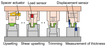
Fig. 3. Press die set with measurement and feedback components.
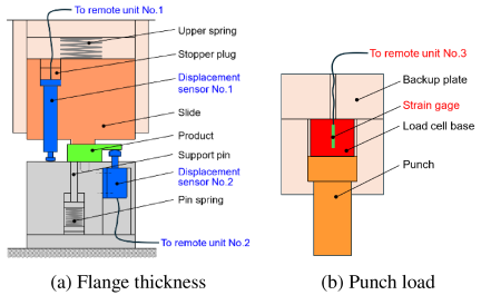
Fig. 4. Illustration of measurement and shear upsetting stages in press die.
Figure 4 illustrates the measurement of the flange thickness and punch load in the die set. The flange thickness was obtained with the two displacement sensors (Muratec, MEL1007 and BIC0308, repeatability: 2 μm) embedded in the upper and lower dies. The difference between the two outputs near the bottom dead center corresponds to the thickness. The sensor outputs were transferred to remote units 1 and 2. The punch load in the shear upsetting was obtained using a strain gauge in the load cell base placed in series with the punch. The output was transferred to remote unit 3.
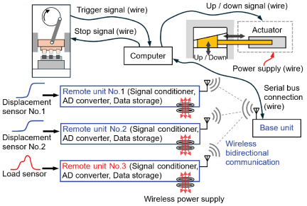
Fig. 5. Schematic of measurement and feedback system.
A schematic of the measurement and feedback systems is shown in Fig. 5. Two displacement sensors and one load sensor were connected to the three remote units, as mentioned earlier. The base unit for wireless data transmission was connected to a computer. Electrical power to the three remote units was supplied using a wireless power transmission device. A trigger signal was generated to start data logging when the upper slide of the press machine reached a specific position. The computer requested three remote units through the base unit to capture the time variations in the displacements and strain from the sensors embedded in the die set. The wireless connection between the remote units set on the die set and the base unit installed on the press column not only provides good operability of the die set but also prevents incorrect wiring connections by operators owing to its complexity.
A threshold-type discrete feedback control was adopted to maintain the product dimensions within a specified range. If the measured flange thickness exceeded tolerance, the computer sent a feedback signal to actuate the wedge-shaped spacer to increase or decrease the thickness by 0.02 mm. The actuator position remained unchanged when the thickness was within the tolerance. In mass-production processes, such as plastic forming, where product dimensions gradually change during production, using this type of feedback control is suitable. This method can be generalized for other forming processes; however, the control limit and command increment must be determined for each product and die set.
The strain of the load cell was monitored at each shot. The characteristics of time variation were used to detect punch fractures. In rare cases, data loss may occur during the data transmission. In this case, the computer requests that the base unit send the data again.
2.2. Detection Device
A general view of the developed press die set and measurement stage of the flange thickness is shown in Fig. 6. The material was fed into the die set from the left side in Fig. 6(a). The thickness was measured during the final stage, as shown in Fig. 6(b). Two power sender units were mounted on the press column, and the corresponding receivers were attached to the upper and lower plates of the dies. The base unit for the data transmission was attached to a press column. One remote unit was visible, whereas the others were hidden behind the die set. The pressing machine was operated at 30 strokes/min.
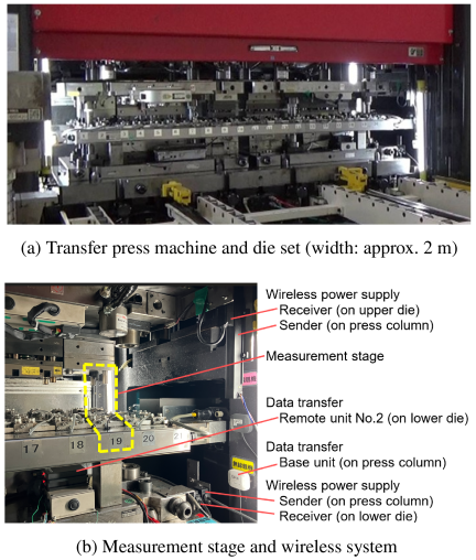
Fig. 6. Press die set with feedback and measurement systems.
Figure 7 shows an example of the raw signal outputs from the displacement sensors and the values indicated in the thickness measurement. The data-sampling interval was 1 ms. There was an unavoidable time lag between the two sensors, with a maximum of approximately 30 ms, as shown in Fig. 7(a). However, after approximately 150 or 180 ms, when the press slide was located near the bottom dead center, a plateau was observed in each sensor signal. The duration of each plateau was longer than the time lag. Hence, even without signal synchronization, the plateau obtained by taking the difference between the two sensor signals was sufficiently longer than the time lag. Therefore, the flange thickness could be determined based on this difference.
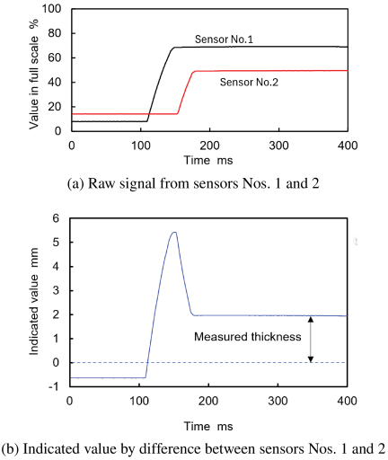
Fig. 7. Measurement of product thickness.
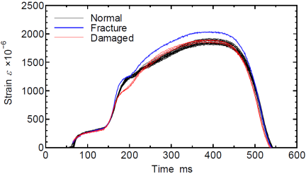
Fig. 8. Variations in strain in the load cell with punch fracture.
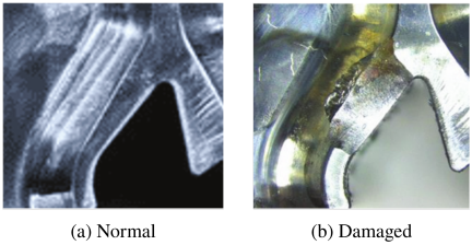
Fig. 9. Punch surface fracture at the shear upsetting stage.
Figure 8 shows the time variation in the strain of the load cell embedded in the shear upsetting stage. Examples of the normal and damaged punches are shown in Fig. 9. The peak punch strain increased at the shot where the fracture occurred, and the small piece separated from the punch was located between the material and the punch. When the damaged punch continued to be used without replacement, the peak of the punch strain returned to almost the same level as that of a normal punch. However, there was an apparent difference between the normal and damaged punches at a forming time of approximately 200 ms. Consequently, this difference was used to detect the punch fracture in this study.
The Mahalanobis method may be applicable to classify phenomena that cannot be expressed by a single scalar value, such as the peak load. The quality classification of complex products has been successfully demonstrated 20. In the milling process, this method has proven useful for classifying tool wear and fracture using multi-sensor signals 21. Punch fractures seldom occur in the press-forming process. This method is suitable because it requires only a small sample of normal data; abnormal samples are not required. The training cost is significantly lower than that of artificial intelligence requiring abnormal data, and the calculation time for the Mahalanobis method is shorter. Hence, this method is suitable for real-time fracture detection in press forming and was adopted in this study.
The Mahalanobis distance is defined as the distance between a point and its distribution. The distance \(d^i\) in the \(i\)-th press shot is calculated by \(d^i=\sqrt{(\boldsymbol{x}^i-\boldsymbol{\mu})^{T}\boldsymbol{\varSigma}^{-1}(\boldsymbol{x}^i-\boldsymbol{\mu})}\). Here, the components of the vector \(\boldsymbol{x}^i\) are the strains from 150 to 270 ms at intervals of 10 ms in the \(i\)-th shot; thus, the dimension is 13. The vector \(\boldsymbol{\mu}\) is averaged over the number of training data. The matrix \(\boldsymbol{\varSigma}\) is the positive semi-definite covariance matrix whose size is \(13\times 13\), and it is averaged over the number of training data.
3. Experimental Results
Figure 10 shows the flange thickness measured over 3,000 shots using the proposed system. With this system, the punch position is adjusted automatically without any manual interruption by the operator. The allowable tolerance was set to be 35% narrower than that in the manually adjusted case. This confirms that the feedback control system was successful. A data transmission failure occurred at the 2572nd shot during the continuous production of 3,000 pieces. However, this had practically no effect on product quality because the data were held in case of failure, and it was very rare for this to occur multiple times in succession. In the continuous production process shown in Fig. 10, the process capability, \(C_{p}\), improved from 2.55 to 4.82. The system was used for the production of 6.5 million pieces; hence, the reproducibility of the control operation was confirmed to be good.
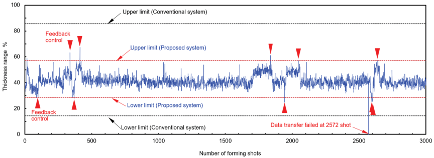
Fig. 10. Thickness change controlled by feedback system during production.
Figure 11 shows the operation of the feedback control system. In this example, decreasing and increasing trends were observed, as shown in Fig. 11(a). The measured thickness below the lower limit of the tolerance was detected at the 496th shot; then, the punch position was commanded to move 0.02 mm upward to increase the thickness. The product formed after feedback control was measured at the 510th shot in Fig. 11(b) because there were multiple stages between the upsetting and measurement stage. Comparing the average thickness for the seven shots before and after the punch movement by feedback control, the flange thickness was automatically adjusted by this feedback control system. A response of 0.016 mm was obtained for the command for a tool travel of 0.02 mm, confirming that the control resolution was sufficient for the set allowable dimensional range.
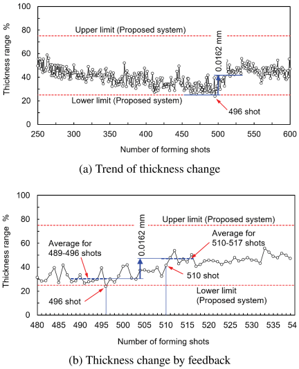
Fig. 11. Thickness change by the proposed control system.
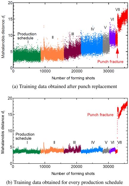
Fig. 12. Mahalanobis distance in production.
Figure 12 shows the variations in the Mahalanobis distance during the production of 36,000 pieces for seven production schedules. In Fig. 12(a), the average vector \(\boldsymbol{\mu}\) and the covariance matrix \(\boldsymbol{\varSigma}\) are determined using the training data of the first 300 shots after the punch replacement. The amount of data was sufficient for a matrix size of \(13\times 13\), considering that the number is usually recommended to be more than 10 times the dimension. However, if the interruption period is long, the die set will not be fully thermally stable after 300 shots or 10 min after production resumes. The Mahalanobis distance exhibits very large fluctuations and changing trends in production schedules.
A significant step-like change was observed between schedules V and VI, in addition to the step at fracture. This phenomenon is attributed to the thermal contraction of the forming tools and the change in frictional conditions, because the temperature of the die set decreases during interruptions. If these effects on dimensional change can be quantitatively addressed, fully automated production may become possible.
Although a significant step owing to punch fracture was observed in production schedule VII, it was impossible to specify a threshold for punch-fracture detection. This fault was improved by changing the training data and obtaining an adjacent average.
In Fig. 12(b), the five-point adjacent averages of the distance are plotted using the training data of the first 300 shots for every production schedule. A noticeable change in the Mahalanobis distance was observed during punch fracture. In the press forming considered here, punch fracture could be judged by using the threshold value of 7.5 for the Mahalanobis distance. To avoid overlooking small tool fractures, the threshold value was set slightly greater than the maximum Mahalanobis distance of 6.5 on a five-point adjacent average during normal production, and the value was set sufficiently smaller than the Mahalanobis distance when fracture occurred. Although the threshold value cannot be applied to other press-forming processes, this determination procedure may be useful for other processes as well.
4. Conclusions
A fully automatic control system with real-time feedback to adjust product dimensions and detect punch fractures was developed for mass production using press forming. In this system, wireless data transmission and a wireless power supply were employed to improve the mountability and operability of the die set for the press machine. The performance was evaluated for continuous production.
-
(1)
The feedback system has been successfully used for the production of more than 6.5 million pieces using a transfer press machine from the middle of 2023 to the end of 2025. Using wireless systems, good operability and easy installation of the die sets could be achieved. These results demonstrate the durability and practicality of this system.
-
(2)
In terms of long-term operation, setting an appropriate threshold range enables the effective feedback control of the part dimensions. Preventing component movement until a threshold is reached eliminates unnecessary operations, thereby suppressing degradation from friction and ensuring system durability and stability. Furthermore, the Mahalanobis method for detecting small punch fractures demonstrates high practicality, as the required training data can be acquired in only 10 min, which is an extremely short duration relative to continuous press forming times.
-
(3)
The product thickness was automatically controlled in the upsetting stage using the developed system, eliminating dimensional defects. The thickness could be adjusted in increments of 0.016 mm using a feedback command of 0.02 mm in a practical example.
-
(4)
The Mahalanobis method was effective for the detection of punch fractures even when the fracture area was relatively small. Large fluctuations in the Mahalanobis distance data could be eliminated by taking the five-point adjacent average. For fracture determination, the training data of the first 300 shots need to be used for each production schedule.
- [1] F. Klocke, S. Kratz, T. Auerbach, S. Gierlings, G. Wirtz, and D. Veselovac, “Process monitoring and control of machining operations,” Int. J. Automation Technol., Vol.5, No.3, pp. 403-411, 2011. https://doi.org/10.20965/ijat.2011.p0403
- [2] Y. Ueno and H. Tachiya, “High-precision machining with positioning control considering structural deformation of small machine-tool,” Int. J. Automation Technol., Vol.19, No.6, pp. 1076-1085, 2025. https://doi.org/10.20965/ijat.2025.p1076
- [3] A. Matsubara and S. Ibaraki, “Monitoring and control of cutting forces in machining processes: A review,” Int. J. Automation Technol., Vol.3, No.4, pp. 445-456, 2009. https://doi.org/10.20965/ijat.2009.p0445
- [4] J. M. Allwood, S. R. Duncan, J. Cao, P. Groche, G. Hirt, B. Kinsey, T. Kuboki, M. Liewald, A. Sterzing, and A. E. Tekkaya, “Closed-loop control of product properties in metal forming,” CIRP Ann., Vol.65, Issue 2, pp. 573-596, 2016. https://doi.org/10.1016/j.cirp.2016.06.002
- [5] J. M. Allwood, O. Music, A. Raithathna, and R. S. Duncan, “Closed-loop feedback control of product properties in flexible metal forming processes with mobile tools,” CIRP Ann., Vol.58, Issue 1, pp. 287-290, 2009. https://doi.org/10.1016/j.cirp.2009.03.065
- [6] C. W. Hsu, A. G. Ulsoy, and M. Y. Demeri, “Development of process control in sheet metal forming,” J. Mater. Process. Technol., Vol.127, Issue 3, pp. 361-368, 2002. https://doi.org/10.1016/S0924-0136(02)00321-7
- [7] T. Bäume, W. Zorn, W. G. Drossel, and G. Rupp, “Iterative process control and sensor evaluation for deep drawing tools with integrated piezoelectric actuators,” Manuf. Rev., Vol.3, No.3, Article No.3, 2016. https://doi.org/10.1051/mfreview/2016002
- [8] Y. Lim, R. Venugopal, and A. G. Ulsoy, “Advances in the control of sheet metal forming,” Proc. 17th World Congr. Int. Fed. Autom. Control, Vol.41, No.2, pp. 1875-1883, 2008. https://doi.org/10.3182/20080706-5-kr-1001.00320
- [9] P. Fischer, J. Heingärtner, W. Aichholzer, D. Hortig, and P. Hora, “Feedback control in deep drawing based on experimental datasets,” J. Phys. Conf. Ser., Vol.896, Article No.012035, 2017. https://doi.org/10.1088/1742-6596/896/1/012035
- [10] K. Siegert and D. Schmoeckel, “Compensation of tilting and horizontal displacement of upper die, relative to the lower die, at out-of-center forming load by a closed-loop control system,” CIRP Ann., Vol.43, Issue 1, pp. 267-270, 1994. https://doi.org/10.1016/S0007-8506(07)62210-0
- [11] P. Groche, J. Hohmann, and D. Ubelacker, “Overview and comparison of different sensor positions and measuring methods for the process force measurement in stamping operations,” Measurement, Vol.135, pp. 122-130, 2019. https://doi.org/10.1016/j.measurement.2018.11.058
- [12] M. Yang and T. Kyuno, “Real time monitoring of friction variation in stamping process using die-embedded sensing system,” Proc. 14th Int. Conf. Technol. Plast., pp. 223-232, 2023. https://doi.org/10.1007/978-3-031-40920-2_24
- [13] B. Endelt, “In-process feedback control of tube hydro-forming process,” Int. J. Adv. Manuf. Technol., Vol.119, Nos.11-12, pp. 7723-7733, 2022. https://doi.org/10.1007/s00170-022-08683-6
- [14] K. Manabe and T. Oguchi, “Sensors and their real in-process control application to advanced deformation processing,” Sens. Mater., Vol.31, No.10, pp. 3155-3162, 2019. https://doi.org/10.18494/SAM.2019.2432
- [15] J. Havinga, T. Boogaard, F. Dallinger, and P. Hora, “Feedforward control of sheet bending based on force measurements,” J. Manuf. Process., Vol.31, pp. 260-272, 2018. https://doi.org/10.1016/j.jmapro.2017.10.011
- [16] M. Rekowski, K. C. Grotzinger, A. Schott, and M. Liewald, “Thin-film sensors for data-driven concentricity prediction in cup backward extrusion,” CIRP Ann., Vol.73, No.1, pp. 205-208, 2024. https://doi.org/10.1016/j.cirp.2024.04.035
- [17] X. He, T. Welo, and J. Ma, “In-process monitoring strategies and methods in metal forming: A selective review,” J. Manuf. Process., Vol.138, pp. 100-128, 2025. https://doi.org/10.1016/j.jmapro.2025.02.011
- [18] Z. Chen, Y. Liu, A. Valera-Medina, and F. Robinson, “Characterizing strip snap in cold rolling process using advanced data analytics,” Procedia CIRP, Vol.81, pp. 453-458, 2019. https://doi.org/10.1016/j.procir.2019.03.078
- [19] J. Cao, M. Bambach, M. Merklein, M. Mozaffar, and T. Xue, “Artificial intelligence in metal forming,” CIRP Ann., Vol.73, Issue 2, pp. 561-587, 2024. https://doi.org/10.1016/j.cirp.2024.04.102
- [20] L. Cheng, V. Yaghoubi, W. V. Paepegem, and M. Kersemans, “Mahalanobis classification system (MCS) integrated with binary particle swarm optimization for robust quality classification of complex metallic turbine blades,” Mech. Syst. Signal Process., Vol.146, Article No.107060, 2021. https://doi.org/10.1016/j.ymssp.2020.107060
- [21] M. Rizal, J. A. Ghani, M. Z. Nuawi, and C. H. C. Haron, “Cutting tool wear classification and detection using multi-sensor signals and mahalanobis-taguchi system,” Wear, Vols.376-377, Part B, pp. 1759-1765, 2017. https://doi.org/10.1016/j.wear.2017.02.017
This article is published under a Creative Commons Attribution-NoDerivatives 4.0 Internationa License.