Research Paper:
Velocity Profile Generation for Industrial Robots Considering Natural Frequency Variations
Shingo Tajima*,†
 , Kazuya Miyashita**, and Hayato Yoshioka***
*Meiji University
1-1-1 Higashimita, Tama-ku, Kawasaki, Kanagawa 214-8570, Japan
†Corresponding author
**Advantest Corporation
Tokyo, Japan
***The University of Tokyo
Tokyo, Japan

Industrial robots are widely used to compensate for labor shortages and increase productivity. However, the natural frequency of a robot varies with its posture, making vibration suppression difficult. Residual vibration during operation increases the cycle time and reduces workpiece accuracy. Therefore, a velocity profile generation method that accounts for posture-dependent frequency variation is required to achieve high-precision robot machining. This study proposes a novel velocity profile generation method to suppress vibration in industrial robots with posture-dependent natural frequency variations. First, finite impulse response filtering and the jerk limited acceleration profile were applied to generate velocity profiles that remove different frequency components during the acceleration and deceleration phases. Next, two methods were developed for determining the suppressed frequencies: (1) filtering the natural frequencies at the start and end of the motion and (2) eliminating the frequency that minimizes the amplitude integral of the acceleration. The simulation results confirmed that the proposed trajectory generation method can reduce vibration, compared with the conventional filtering method, for both suppressed frequency-determination methods. The optimal velocity profile was achieved by filtering the frequency that minimizes the amplitude integral of the acceleration during the acceleration phase and the natural frequency at the end of the motion during the deceleration phase. The proposed method provides a practical solution for improving the dynamic performance of industrial robots by effectively suppressing vibration while maintaining motion efficiency.
1. Introduction
In recent years, industrial robots have been rapidly introduced in various fields, including the manufacturing industry, and their utilization has continued to expand in the automotive, electronics manufacturing, food processing, and other production industries 1. In particular, articulated industrial robots are widely used in various processes, such as assembly, welding, and cutting, because of their high degrees of freedom and wide range of motion 2,3,4,5,6,7. With the widespread use of these industrial robots, the demands for high-speed and high-precision operations have created a critical problem: the vibrations that are generated during operation adversely affect productivity and processing accuracy.
The vibrations of industrial robots are particularly significant during high-speed operation, causing problems such as reduced machining accuracy, increased product defect rates, and shortened robot lifetimes 8,9. Therefore, several research projects on vibration suppression have been conducted and various approaches have been proposed, such as feedforward control based on inverse dynamics 10,11, velocity profile generation that avoids resonance frequencies 12, and hybrid methods combined with feedback control 13. However, most of these conventional methods assume that the structural stiffness of the robot is constant and are often limited to vibration suppression for a specific natural frequency.
Many studies on trajectory generation methods have been conducted for three-axis and five-axis machine tools 14,15,16,17,18,19,20,21. These trajectory optimization methods have been proposed to improve the machining accuracy and reduce the machining time 22,23. Because these machine tools have highly rigid structures, their natural frequencies do not change significantly during operation. Therefore, vibration suppression functions effectively by generating trajectories based on a fixed resonance frequency. As a result, the stability of the machining accuracy is guaranteed and high-speed machining is realized.
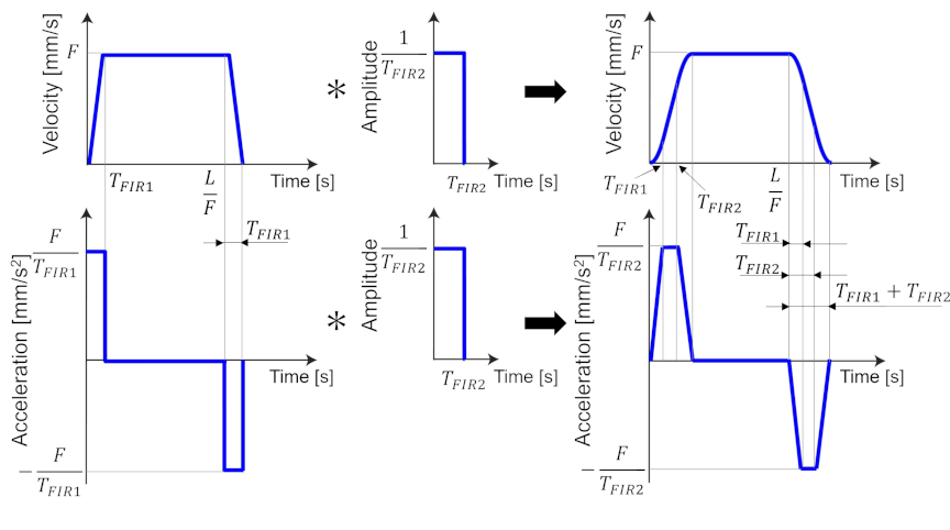
Fig. 1. Trajectory generation using the FIR filter.
However, in contrast to machine tools, the rigidity of industrial robots varies significantly depending on the joint angles and link arrangements owing to their structural characteristics. This implies that the natural frequency of a robot changes significantly depending on its posture 24,25. Therefore, conventional trajectory generation methods, which assume that the natural frequency is constant regardless of the posture, cannot suppress vibrations over the entire range of motion of the robot 11,26,27,28. Particularly in high-precision machining and assembly processes, this problem has serious adverse effects on product quality and production efficiency. Consequently, it is crucial to develop trajectory generation methods that consider the posture dependence of industrial robots 29.
This study proposes a novel velocity profile generation method for industrial robots that considers the posture-dependent natural frequency variations. The proposed method aims to effectively reduce machine-body vibration during operation by generating velocity profiles that adapt to changes in the natural frequencies of each posture on the motion trajectory of the robot. This method enables high-speed and high-precision operation of industrial robots by reducing vibration caused by posture dependence.
2. Trajectory Generation Methods Considering Frequency Components
Vibration suppression is essential for high-speed and high-precision trajectory generation. In flexible-structure systems, such as industrial robots, sudden changes in acceleration trigger unwanted vibrations that can seriously affect the accuracy and stability of the motion. These vibrations not only reduce the machining accuracy and cause product defects but also reduce the durability and safety of the entire system.
Several trajectory generation methods that consider frequency components have been proposed to avoid the resonant frequencies of mechanical systems and suppress vibrations. Among these, velocity profiles with trapezoidal acceleration can generate trajectories that avoid resonance frequencies owing to their ability to control the maximum acceleration and its rate of change. These profiles are widely used in machine tools because of their superior vibration suppression and applicability in high-speed and high-precision dynamic systems.
This section describes two typical trajectory generation methods that consider frequency components: the finite impulse response (FIR) filtering method and jerk limited acceleration profile (JLAP) method.
2.1. FIR Filtering-Based Velocity Profile Generation Method
One method for generating velocity profiles with trapezoidal acceleration is to use an FIR filter, which can remove arbitrary frequency components 22. This method can generate input trajectories that do not contain frequency components corresponding to the natural frequencies of the system, thereby enabling effective vibration suppression.
The transfer function of a first-order FIR filter is defined as follows:
Figure 1 shows the trajectory generation by the FIR filter. When a rectangular velocity pulse is convolved with an FIR filter, a trapezoidal velocity profile can be obtained. Furthermore, a smoother velocity profile can be generated by convolving another FIR filter with the obtained trapezoidal velocity. The resulting acceleration profile has a trapezoidal shape. Therefore, a velocity profile with trapezoidal acceleration can be easily generated using two FIR filters.
The velocity profile generation method using the FIR filter provides a constant frequency response for the entire velocity profile. Consequently, specific frequency components can be effectively removed such that vibration can be suppressed. However, this method faces challenges when the dynamic characteristics of the system change.
This problem becomes particularly important when applied to industrial robots, whose natural frequencies vary depending on their posture. Assuming that the natural frequency at the beginning of the motion is \(f_s\) and that at the end of the motion is \(f_e\), both frequencies can be removed from the entire velocity profile using a second-order FIR filter. However, this filtering-based method unnecessarily removes \(f_e\) at the beginning of the motion and \(f_s\) at the end. Because applying each filter increases the cycle time, this method reduces productivity and does not achieve optimal vibration suppression.
This problem is one of the major challenges in applying the FIR filter-based velocity profile generation method to industrial robots with varying natural frequencies.
2.2. JLAP Method
JLAP is a motion planning technique that limits the rate of change in acceleration (jerk) to ensure smooth transitions between different motion phases 23. By controlling the jerk, the profile reduces abrupt force changes, thereby minimizing system vibration and mechanical stress. This approach is commonly used in CNC machines and industrial robotics to achieve high accuracy and smooth motion while improving system lifetime and stability.
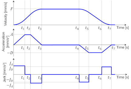
Fig. 2. Trajectory generation based on the jerk limited acceleration profile (JLAP).
Figure 2 illustrates the velocity profile generation based on JLAP. As shown in Fig. 2, in JLAP, the velocity profile is calculated based on the target travel distance \(L\), velocity \(F\), acceleration \(A\), deceleration \(D\), jerk during acceleration \(J_A\), and jerk during deceleration \(J_D\). The formula for calculating the velocity profile using JLAP is
where
JLAP determines the frequencies to be removed from the generated trajectory based on the set velocity, acceleration, and jerk. Therefore, in contrast to trajectory generation using FIR filters, JLAP cannot selectively suppress arbitrary frequencies for vibration suppression.
To generate a velocity profile that suppresses vibrations, the trajectory must be generated without exciting the natural frequencies of the system. However, because JLAP does not allow the flexible adjustment of the frequencies to be removed, the vibration caused by the natural frequencies may not be sufficiently suppressed. This limitation is the main problem with JLAP, making it unsuitable for vibration suppression of systems with specific vibration characteristics.
3. Velocity Profile Generation Method Capable of Suppressing Different Frequencies
The velocity profile that should be applied to a robot whose natural vibration varies with its posture can remove arbitrary frequencies that differ between acceleration and deceleration. This study proposes a velocity profile generation method based on JLAP with the addition of FIR filter characteristics.
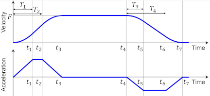
Fig. 3. Generated velocity profile based on the delay time \(T_i\).
Figure 3 illustrates the proposed trajectory generation method for systems with varying frequency characteristics. The proposed method generates a velocity profile using the natural frequencies to be suppressed, travel distance, and command velocity. As shown in Fig. 3, the delay time \(T_i\) is obtained from the target frequency to be suppressed \(f_i\) as \(T_i=1/f_i\). Using the calculated delay time \(T_i\), the vibrations caused by the frequencies \(f_1\) and \(f_2\) during acceleration and \(f_3\) and \(f_4\) during deceleration can be suppressed.
Equations for the velocity profile are derived to formulate the proposed trajectory generation method, which combines the characteristics of FIR filtering with JLAP. Unknown variables are introduced into the velocity profile shown in Fig. 3, and continuity conditions are applied for both the velocity and acceleration. The velocity profile equation can be formulated by determining these unknown variables.
Because the desired velocity profile consists of trapezoidal acceleration, the polynomal orders in the velocity equation are known. The velocity profiles for the \(i\)-th duration can be expressed using the parameters \(\alpha_i\) and \(\beta_i\) as follows:
The acceleration waveform for this velocity profile can be expressed as follows by applying time differentiation:
By applying the continuity conditions of the velocity and acceleration to Eqs. \(\eqref{eq:4}\) and \(\eqref{eq:6}\), the following equations are derived as constraints for the velocity profile:
From the obtained Eqs. \(\eqref{eq:7}\) and \(\eqref{eq:8}\), the parameters \(\alpha_i\) and \(\beta_i\) can be calculated as follows:
Therefore, by substituting the calculated parameters in Eq. \(\eqref{eq:9}\) into Eq. \(\eqref{eq:4}\), the velocity profile can be derived as shown in the equation below.
Using the proposed velocity profile, it is possible to remove the frequency components \(f_1=1/T_1\) and \(f_2=1/T_2\) during acceleration and \(f_3=1/T_3\) and \(f_4=1/T_4\) during deceleration from the generated trajectory. As a result, vibration can be effectively suppressed even when the natural frequency changes during operation, such as in industrial robots. In addition, productivity can be improved by preventing unnecessary elongation of the cycle time.
4. Determination of Frequency Components to Be Suppressed in Operating Robots
This section proposes methods for determining the frequency components \(f_i\) to be removed from the trajectory using the velocity profile generation method proposed in the previous section.
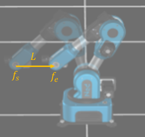
Fig. 4. Robot travel distance and change in natural frequency.
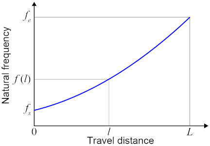
Fig. 5. Variation in natural frequency with travel distance.
4.1. Change in Natural Frequency of the Industrial Robot
The robot model used in this study is shown in Fig. 4. As shown in Fig. 5, the natural frequency of the robot changes from \(f_s\) to \(f_e\) when the robot moves the desired travel distance \(L\). Vibration occurs significantly at the start and end of movement and less during constant-velocity movement. Therefore, this study focuses on the acceleration and deceleration durations at the start and end of the movement, during which the vibration is particularly large.
The verification in this study was conducted based on the assumption that the natural frequency of an industrial robot changes monotonically with the travel distance, as shown in Fig. 5, for clarity and ease of explanation. It should be noted that the proposed method does not rely on this monotonic assumption and is applicable to more general cases in which the natural frequency varies non-monotonically.
Therefore, when the robot moves a distance \(l\), its natural frequency \(f\) can be determined using the following equation:
Here, \(f_p\) is the peak value of the parabolic curve.
Two methods for determining the frequency components of the robot model to be suppressed with varying natural frequencies are proposed in the following subsections.
4.2. Determination Method Based on Natural Frequency at Start and End Points
The first proposed method is the start and end point reference method. This method determines the frequencies \(f_1\), \(f_2\), \(f_3\), and \(f_4\) to be removed based on the natural frequencies at the start and end points of the robot movement. Based on the conditions of the robot model used in this study, as described in the previous section, the natural frequency at the starting point of the movement is set to \(f_s\), and the natural frequency at the end point of the movement is set to \(f_e\). According to these conditions, the frequencies \(f_1\) and \(f_2\) to be removed during acceleration and \(f_3\) and \(f_4\) to be removed during deceleration are determined using the following equations:
This method effectively eliminates the major resonance frequencies at the start and end points of the robot movement trajectory. Consequently, the vibration suppression performance of the robot during movement can be improved.
4.3. Determination Method Based on Minimization of Amplitude Integral Values
The second proposed method determines the frequencies to be removed by focusing on the frequency components during acceleration and deceleration. This method determines the removal frequency \(f_i\) to minimize the specific frequency region included in the acceleration profile during the acceleration and deceleration of the robot motion.
The method for determining removal frequencies \(f_1\) and \(f_2\) during acceleration is described below. The removal frequencies \(f_3\) and \(f_4\) during deceleration can be calculated in the same manner.
First, regarding the acceleration profile used in this study, as shown in Fig. 3, the Laplace transform of the acceleration profile during acceleration can be expressed using the following equation:
For this equation, the amplitude of the acceleration profile is calculated as follows:
Here, substituting \(\omega=2\pi f\), \(f_1=1/T_1\), and \(f_2=1/T_2\) into Eq. \(\eqref{eq:14}\) yields
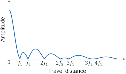
Fig. 6. Frequency characteristics of acceleration profile during acceleration duration.
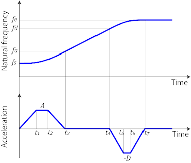
Fig. 7. Time variation of natural frequency with acceleration profile.
The frequency response of the acceleration profile generated by the proposed trajectory generation method according to Eq. \(\eqref{eq:15}\) is shown in Fig. 6. As shown in Fig. 6, the amplitude drops at the integer multiples of \(f_1=1/T_1\) and \(f_2=1/T_2\). Thus, the selected frequency components are removed from the generated trajectory. Note that Fig. 6 has the same waveform as the impulse response of the second-order FIR filter.
Figure 7 illustrates how the natural frequencies change during acceleration and deceleration. As shown in Fig. 7, the natural frequency of the robot at the end of acceleration is \(f_a\) and that at the start of deceleration is \(f_d\). Thus, the natural frequency of the robot changes from \(f_s\) to \(f_a\) during acceleration and from \(f_d\) to \(f_e\) during deceleration.
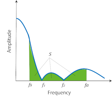
Fig. 8. Sum of the amplitudes in the frequency domain.
Figure 8 shows the frequency response of the acceleration used in the proposed frequency selection method. As shown in Fig. 8, the proposed frequency selection method determines the frequencies \(f_1\) and \(f_2\) to be removed during acceleration to minimize the integral value \(S\) of the amplitude in the frequency range from \(f_s\) to \(f_a\). Because the natural frequencies during acceleration vary from \(f_s\) to \(f_a\), minimizing the sum of the amplitudes of the frequency components in this range enables vibration suppression. The frequencies \(f_3\) and \(f_4\) to be removed during deceleration are also determined to minimize the amplitude integral over the frequency range from \(f_d\) to \(f_e\).
The frequencies \(f_1\) and \(f_2\) are calculated using the frequency selection method proposed in this section. First, to determine the intended frequency range, the natural frequency of the robot at the end of the acceleration \(f_a\) is obtained. The distance \(l_a\) traveled until the end of the acceleration duration can be expressed as
Therefore, the natural frequency of the robot at the end of acceleration, \(f_a\), can be calculated by substituting Eq. \(\eqref{eq:16}\) into Eq. \(\eqref{eq:11}\), using the following equation:
The amplitude integral value \(S\) in Fig. 8 is then expressed as follows:
Note that, in Eq. \(\eqref{eq:18}\), assuming that the frequency variable \(f\) and removal frequencies \(f_1\) and \(f_2\) are similar, the approximation is applied as \(\sin(x)=x\).
The conditions required to minimize \(S\) in Eq. \(\eqref{eq:18}\) are \(\partial S/\partial f_1=0\) and \(\partial S/\partial f_2=0\). By solving for \(f_1\) and \(f_2\) using these conditions, the removal frequencies that minimize \(S\) can be selected. The following equations provide the obtained removal frequencies.
The removal frequencies \(f_1\) and \(f_2\) are obtained by solving numerically using Eqs. \(\eqref{eq:17}\) and \(\eqref{eq:19}\), with \(f_1=f_2=f_s\) as the initial values. The frequencies \(f_3\) and \(f_4\) during deceleration are determined using the same calculation process.
This method is known as the minimum amplitude integral value method and the simulation thereof is described in Section 5 for comparison with the previous FIR filter and start and end point reference methods.
5. Simulation Results
This section verifies the usefulness of the proposed trajectory generation method for industrial robots whose natural frequencies vary with their posture. The frequency selection methods, namely the start and end point reference method (Section 4.2) and the minimum amplitude integral method (Section 4.3), were also comparatively verified through simulations.
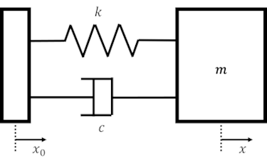
Fig. 9. Robot model with one-degree-of-freedom vibration system.
5.1. Robot Model with Time-Varying Transfer Function
This section explains the robot model used in the simulation.
In this study, the robot was modeled as a one-degree-of-freedom vibration system, as shown in Fig. 9, and the external input to the system was the velocity input to \(x\), where \(m\) is the mass of the system, \(k\) is the spring stiffness coefficient, and \(c\) is the viscous damping coefficient.
For the model shown in Fig. 9, the equation of motion is expressed as follows:
Let \(\omega_n=\sqrt{k/m}\) for the natural angular frequency and \(\zeta=c/(2\sqrt{mk})\) for the damping ratio. By applying the Laplace transform, the transfer function of the system can be obtained as follows:
In the robot system in this study, it is assumed that the natural frequency varies with time as \(\omega_n(t)\). Thus, the proposed method was verified through simulations using a time-varying transfer function.
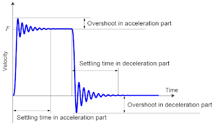
Fig. 10. Definition of overshoot value and settling time.
5.2. Simulation Conditions
The Varying Transfer Function block in Simulink was used to simulate the system using the time-varying transfer function presented in the previous section. This function block is suitable for modeling systems with time-varying characteristics because it allows the definition of transfer functions with variable coefficients. During the simulations, the proposed trajectory generation method based on the two frequency selection methods for varying natural frequencies was compared with the conventional trajectory generation method based on a second-order FIR filter. The overshoot value and settling time shown in Fig. 10 were used as the evaluation parameters. The settling time is defined as the time until the velocity deviation falls within \(\pm 0.1{\%}\) of the velocity change.
The simulation conditions were set as follows: target travel distance \(L=100\) mm, target velocity \(F=50\) mm/s, and damping ratio \(\zeta=0.05\). The natural frequency of the robot was assumed to vary proportionally to the travel distance, and two cases were considered: increasing from \(f_s=8\) Hz to \(f_e=20\) Hz and decreasing from \(f_s=20\) Hz to \(f_e=8\) Hz.
5.3. Evaluation of Overshoot Value and Settling Time Comparison
The simulation results for the velocity profiles of the one-degree-of-freedom vibration system are shown in Fig. 11. The velocity profiles were obtained using both the conventional and proposed methods. In this case, the natural frequency of the robot increased from \(f_s=8\) Hz to \(f_e=20\) Hz.
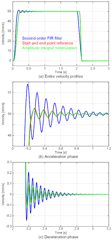
Fig. 11. Velocity response to the input velocity profile generated by each method.
Figure 11 shows that the proposed trajectory generation methods using the two frequency selection methods had smaller overshoots and settling times than the conventional method using a second-order FIR filter. These results indicate that the proposed trajectory generation method for the varying natural frequency system is useful for vibration suppression in robot control.
It should be noted that the effect of the proposed method during the deceleration phase may appear smaller than that during the acceleration phase because the FIR filter used in the conventional method acts as a low-pass filter and suppresses vibrations even at higher natural frequencies.
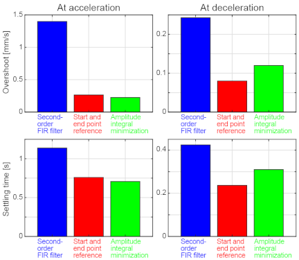
Fig. 12. Overshoot value and settling time with monotonically increasing natural frequencies.
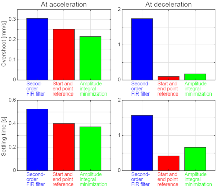
Fig. 13. Overshoot value and settling time with monotonically decreasing natural frequencies.
Figure 12 compares the overshoot value and settling time under the condition of monotonically increasing natural frequencies. As shown in Fig. 12, in the acceleration phase, determining the removal frequency using the minimum amplitude integral value method more effectively suppressed the oscillations. However, in the deceleration phase, vibration suppression was more effective when the start and end point reference method was used.
Figure 13 shows the comparison results for the monotonically decreasing natural frequency case. As shown in Fig. 13, the same characteristics were observed for decreasing natural frequencies. The minimum amplitude integral value method was more suitable for the acceleration section, whereas the start and end point reference method was more suitable for the deceleration section. This indicates that the proposed method for determining the removal frequency differs for the acceleration and deceleration sections.
During the acceleration phase, the natural frequency of the robot varied as it moved away from its initial value at the start point. Consequently, the start and end point reference method, which eliminates the natural frequency at the starting point, was less effective. Instead, the amplitude integral minimization method, which minimizes the amplitude area of the frequencies that the robot may exhibit during acceleration, provided superior vibration suppression.
In contrast, in the deceleration phase, the natural frequency remained constant after the robot reached a stopping point. The start and end point reference method, which targets the natural frequency at the end point, proved to be more effective for vibration suppression than the amplitude integral minimization method in this phase.
This behavior indicates that vibration suppression during acceleration is governed by the cumulative effect over the entire acceleration interval, whereas vibration suppression during deceleration is dominated by the residual vibration in the final configuration following motion termination.
Based on these results, the optimal velocity profile for vibration suppression was achieved by applying the amplitude integral minimization method in the acceleration phase and the start and end point reference method in the deceleration phase to determine the removal frequency.
6. Conclusions
This study focused on developing a vibration-suppressing velocity profile generation method that is suitable for systems with varying natural frequencies, such as industrial robots. To achieve this, we proposed a trajectory generation method that applies the JLAP and a second-order FIR filter.
Analytical equations were derived to generate velocity profiles based on the frequencies to be suppressed in both the acceleration and deceleration phases. In addition, two methods for determining the frequencies to be suppressed were proposed: the start and end point reference method and the amplitude integral minimization method. The effectiveness of these methods was evaluated through simulations.
The simulation results demonstrate the feasibility of the proposed methods and identify the optimal velocity profile generation method for effective vibration suppression.
Acknowledgments
This work was supported by JSPS KAKENHI Grant Numbers 23K13229 and 25K01140.
- [1] A. Verl, A. Valente, S. Melkote, C. Brecher, E. Ozturk, and L. T. Tunc, “Robots in machining,” CIRP Annals, Vol.68, Issue 2, pp. 799-822, 2019. https://doi.org/10.1016/j.cirp.2019.05.009
- [2] C. S. Chen and S. K. Chen, “Synchronization of tool tip trajectory and attitude based on the surface characteristics of workpiece for 6-DOF robot manipulator,” Robotics and Computer-Integrated Manufacturing, Vol.59, pp. 13-27, 2019. https://doi.org/10.1016/j.rcim.2019.01.016
- [3] Y. Chen and F. Dong, “Robot machining: Recent development and future research issues,” The Int. J. of Advanced Manufacturing Technology, Vol.66, pp. 1489-1497, 2013. https://doi.org/10.1007/s00170-012-4433-4
- [4] B. Greenway, “Robot accuracy,” Industrial Robot, Vol.27, Issue 4, pp. 257-265, 2000. https://doi.org/10.1108/01439910010372136
- [5] S. Tajima, S. Iwamoto, and H. Yoshioka, “Kinematic tool-path smoothing for 6-axis industrial machining robots,” Int. J. Automation Technol., Vol.15, No.5, pp. 621-630, 2021. https://doi.org/10.20965/ijat.2021.p0621
- [6] V. Milenkovic and B. Huang, “Kinematics of major robot linkages,” Robotics Int. of SME, Vol.2, pp. 16-31, 1983.
- [7] M. Dupac, “Smooth trajectory generation for rotating extensible manipulators,” Mathematical Methods in the Applied Sciences, Vol.41, Issue 6, pp. 2281-2286, 2018. https://doi.org/10.1002/mma.4210
- [8] M. Beschi, S. Mutti, G. Nicola, M. Faroni, P. Magnoni, E. Villagrossi, and N. Pedrocchi, “Optimal robot motion planning of redundant robots in machining and additive manufacturing applications,” Electronics, Vol.8, Issue 12, Article No.1437, 2019. https://doi.org/10.3390/electronics8121437
- [9] R. Béarée and A. Olabi, “Dissociated jerk-limited trajectory applied to time-varying vibration reduction,” Robotics and Computer-Integrated Manufacturing, Vol.29, Issue 2, pp. 444-453, 2013. https://doi.org/10.1016/j.rcim.2012.09.014
- [10] K. P. Jankowski and H. A. Elmaraghy, “Inverse dynamics and feedforward controllers for high precision position/force tracking of flexible joint robots,” Robotica, Vol.12, Issue 3, pp. 227-241, 1994. https://doi.org/10.1017/S0263574700017203
- [11] S. Tajima, S. Iwamoto, and H. Yoshioka, “Posture optimization in robot machining with kinematic redundancy for high-precision positioning,” Int. J. Automation Technol., Vol.17, No.5, pp. 494-503, 2023. https://doi.org/10.20965/ijat.2023.p0494
- [12] E. Bayo and B. Paden, “On trajectory generation for flexible robots,” J. of Robotic Systems, Vol.4, Issue 2, pp. 229-235, 1987. https://doi.org/10.1002/rob.4620040206
- [13] D. Jeon and M. Tomizuka, “Learning hybrid force and position control of robot manipulators,” IEEE Trans. on Robotics and Automation, Vol.9, Issue 4, pp. 423-431, 1993. https://doi.org/10.1109/70.246053
- [14] B. Sencer and S. Tajima, “Frequency optimal feed motion planning in computer numerical controlled machine tools for vibration avoidance,” J. of Manufacturing Science and Engineering, Vol.139, Issue 1, Article No.011006, 2017. https://doi.org/10.1115/1.4034140
- [15] S. Tajima and B. Sencer, “Kinematic corner smoothing for high-speed machine tools,” Int. J. of Machine Tools and Manufacture, Vol.108, pp. 27-43, 2016. https://doi.org/10.1016/j.ijmachtools.2016.05.009
- [16] W. Wang, C. Hu, K. Zhou, and S. He, “Corner trajectory smoothing with asymmetrical transition profile for CNC machine tools,” Int. J. of Machine Tools and Manufacture, Vol.144, Article No.103423, 2019. https://doi.org/10.1016/j.ijmachtools.2019.05.007
- [17] K. Nakamoto and Y. Takeuchi, “Recent advances in multiaxis control and multitasking machining,” Int. J. Automation Technol., Vol.11, No.2, pp. 140-154, 2017. https://doi.org/10.20965/ijat.2017.p0140
- [18] T. Haas, S. Weikert, and K. Wegener, “MPCC-based set point optimisation for machine tools,” Int. J. Automation Technol., Vol.13, No.3, pp. 407-418, 2019. https://doi.org/10.20965/ijat.2019.p0407
- [19] S. Tajima and B. Sencer, “Accurate real-time interpolation of 5-axis tool-paths with local corner smoothing,” Int. J. of Machine Tools and Manufacture, Vol.142, pp. 1-15, 2019. https://doi.org/10.1016/j.ijmachtools.2019.04.005
- [20] F. Sellmann, T. Haas, H. Nguyen, S. Weikert, and K. Wegener, “Geometry optimisation for 2D cutting: A quadratic programming approach,” Int. J. Automation Technol., Vol.10, No.2, pp. 272-281, 2016. https://doi.org/10.20965/ijat.2016.p0272
- [21] S. Tajima and B. Sencer, “Online interpolation of 5-axis machining toolpaths with global blending,” Int. J. of Machine Tools and Manufacture, Vol.175, Article No.103862, 2022. https://doi.org/10.1016/j.ijmachtools.2022.103862
- [22] L. Biagiotti and C. Melchiorri, “FIR filters for online trajectory planning with time- and frequency-domain specifications,” Control Engineering Practice, Vol.20, Issue 12, pp. 1385-1399, 2012. https://doi.org/10.1016/j.conengprac.2012.08.005
- [23] K. Erkorkmaz and Y. Altintas, “High speed CNC system design. Part I: Jerk limited trajectory generation and quintic spline interpolation,” Int. J. of Machine Tools and Manufacture, Vol.41, Issue 9, pp. 1323-1345, 2001. https://doi.org/10.1016/S0890-6955(01)00002-5
- [24] D. K. Thomsen, R. Søe-Knudsen, O. Balling, and X. Zhang, “Vibration control of industrial robot arms by multi-mode time-varying input shaping,” Mechanism and Machine Theory, Vol.155, Article No.104072, 2021. https://doi.org/10.1016/j.mechmachtheory.2020.104072
- [25] R. Sato, Y. Ito, S. Mizuura, and K. Shirase, “Vibration mode and motion trajectory simulations of an articulated robot by a dynamic model considering joint bearing stiffness,” Int. J. Automation Technol., Vol.15, No.5, pp. 631-640, 2021. https://doi.org/10.20965/ijat.2021.p0631
- [26] D. Verscheure, B. Demeulenaere, J. Swevers, J. D. Schutter, and M. Diehl, “Time-optimal path tracking for robots: A convex optimization approach,” IEEE Trans. on Automatic Control, Vol.54, Issue 10, pp. 2318-2327, 2009. https://doi.org/10.1109/TAC.2009.2028959
- [27] K. Hu, Y. Dong, and D. Wu, “Smooth time-optimal path tracking for robot manipulators with kinematic constraints,” Proc. of ASME 2020 Int. Mechanical Engineering Congress and Exposition, Vol.7B, Article No.V07BT07A038, 2020. https://doi.org/10.1115/IMECE2020-23637
- [28] J. Yang, D. Li, C. Ye, and H. Ding, “An analytical C3 continuous tool path corner smoothing algorithm for 6R robot manipulator,” Robotics and Computer Integrated Manufacturing, Vol.64, Article No.101947, 2020. https://doi.org/10.1016/j.rcim.2020.101947
- [29] R. Zhao and S. Ratchev, “On-line trajectory planning with timevariant motion constraints for industrial robot manipulators,” Proc. of 2017 IEEE Int. Conf. on Robotics and Automation (ICRA), pp. 3748-3753, 2017. https://doi.org/10.5772/5032
This article is published under a Creative Commons Attribution-NoDerivatives 4.0 Internationa License.