Research Paper:
Precision Milling of Microstructures on Rubber Surfaces for Burr-Free and High-Accuracy Fabrication
Asuka Aoyagi and Hideo Takino†

Chiba Institute of Technology
2-17-1 Tsudanuma, Narashino, Chiba 275-0016, Japan
†Corresponding author

In this study, the milling of submillimeter-deep stepped micro-grooves on nitrile rubber surfaces was investigated. Rubber products with microstructured surfaces are typically manufactured by molding, which is costly and unsuitable for prototyping or small-lot production. Machining provides a promising alternative but faces challenges due to rubber’s flexibility and elastic deformation. Experiments were conducted using a numerically controlled milling machine and cemented carbide end mills with different twist directions and angles. The experiments compared left-twist and right-twist tools, whereras left-twist tools have cutting edges twisted opposite to the conventional right-twist tools. The effects of twist angle and feed rate on burr formation and dimensional accuracy were evaluated in detail. As a result, burr formation was notably suppressed with the left-twist tool, especially at larger twist angles and lower feed rates. In contrast, right-twist tools produced significant burrs and residues due to chip deformation and bouncing. Moreover, cross-sectional profiles measured by laser profilometry revealed that depth errors decreased as feed rate and twist angle decreased. These errors are attributed to elastic deformation and recovery of the rubber surface induced by cutting forces. These findings demonstrate that appropriate tool geometry and machining parameters can achieve burr-free, high-precision stepped microgroove milling on nitrile rubber. These results also provide important insights for the cost-effective and rapid manufacturing of rubber products with microstructured surfaces, especially suited for small-lot and prototype production.
1. Introduction
Rubber products with microstructures on their surfaces, such as microchannel devices 1 and superhydrophobic rubber sheets 2,3, have been manufactured mainly through molding processes. The complexity of these microstructures has also increased. For example, tire products with complex microstructures on their sidewalls have been commercialized to provide visual decoration by enhancing light absorption 4. In addition, tire products with tiny protrusions or pockets distributed across the entire curved sidewall have been produced to improve cooling performance 5,6,7. Although the shapes of these small protrusions and pockets are simple, their arrangements on curved surfaces are complex. Certain pressure-sensitive sensor products employ arrays of fine conical micropillars composed of a conductive rubber 8. Furthermore, there is a growing demand for devices with increased microchannel complexities 9,10. However, molding is costly and unsuitable for prototypes or small-lot production owing to expensive mold fabrication. If microstructures can be shaped by machining, low-cost and rapid manufacturing of various rubber products is possible. However, owing to the flexibility of rubber, machining is challenging and achieving high precision is difficult.
Various studies have been conducted on rubber-surface machining 11,12,13,14,15,16,17,18,19,20,21,22,23. Jin and Murakawa 11 showed that high-speed milling with a 6-mm-diameter end mill at 40,000 rpm yields accurate and smooth surfaces. Shinozuka and Imakama 13 realized smooth surfaces using tools with microgrooved faces for high-speed orthogonal cutting. Teramoto et al. 14 and Chainawakul et al. 15 modeled rubber end milling and estimated the cutting forces and errors. Some studies have focused on cooling the rubber workpiece to reduce elastic deformation during machining 16,17,18,19,20,21, and others have focused on heating the tool to improve cutting performance 22,23. In a study focusing on burr formation, Shih et al. machined grooves 3.81 mm deep, which are considerably deeper than those used in the present study, in an elastomer composed of synthetic and natural rubbers using various woodworking router bits. Among them, downcut end mills achieved burr-free machining 20. Although the tools used by Shih et al. were woodworking tools, they appear to be essentially equivalent to those employed in the present investigation. Accordingly, the up-cut and down-cut tools reported by Shih et al. are designated here as the right-twist and left-twist tools, respectively, because the twist direction and twist angle of the end mill are regarded as key geometrical parameters in this study. However, Shih et al. primarily focused on burr suppression and did not investigate dimensional accuracy, which is also a critical requirement for precise groove milling, in addition to the absence of burrs.
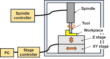
Fig. 1. Schematic of milling machine used in this study. The workpiece was machined by moving it relative to the tool, while the tool was rotated clockwise.
In the present study, we investigated the effects of tool geometry and machining conditions on burr formation and dimensional accuracy in the milling of microstructures, specifically submillimeter-deep stepped micro-grooves, on rubber surfaces. The direct machining of complex surface microstructures on rubber without relying on molding processes is expected to be beneficial for prototyping and small-lot production. Accordingly, as a fundamental investigation into machining-based fabrication of complex surface microstructures, this paper presents the first step toward creating stepped grooves as microstructures through cutting.
2. Experimental Method
A lab-developed numerically controlled (NC) milling machine was used for the experiments. As shown in Fig. 1, the machine consisted of a commercially available XYZ stage, an NC stage controller, a high-speed tool spindle, and a spindle controller. In this configuration, the workpiece was machined by moving it relative to the tool, while the tool was rotated clockwise. An uncoated 5-mm-diameter double-flute square end mill made of cemented carbide was used.
Nitrile rubber was used as the workpiece material. It is widely used in industrial applications, particularly for rubber parts that require oil resistance, wear resistance, and mechanical strength. The hardness of the rubber material measured with a Type A durometer was 62. The dimensions of the workpiece were 50 mm \(\times\) 25 mm \(\times\) 10 mm. The target shape of the microgroove is shown in Fig. 2. As shown in Fig. 2, the groove had stepped features at submillimeter depths. One or two micro-grooves were machined on each workpiece. The workpieces were fixed to aluminum plates using double-sided adhesive tape, and the plates were secured to the machine tool stage with screws.
Machining was performed as follows. As shown in Fig. 3, the stage was fed at the center of a workpiece in the \(y\)-direction with a cut depth of 200 μm (Stage 1), and then the left step (Stage 2) and right step (Stage 3) were machined in the same manner at a depth of 100 μm. The machined length in the \(y\)-direction was 25 mm, which was the length of the workpiece. After machining, the surfaces were visually observed and closely examined using scanning electron microscopy (SEM). Cross-sectional machined profiles were measured using a laser-type three-dimensional surface profiler (Mitaka Kohki, NH-3) 24,25 with a laser spot diameter of approximately 1 μm.
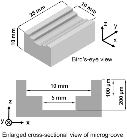
Fig. 2. Target shape. The workpieces were made of nitrile rubber. The dimensions of each workpiece were 50 mm \(\times\) 25 mm \(\times\) 10 mm. One or two micro-grooves were machined on each workpiece.
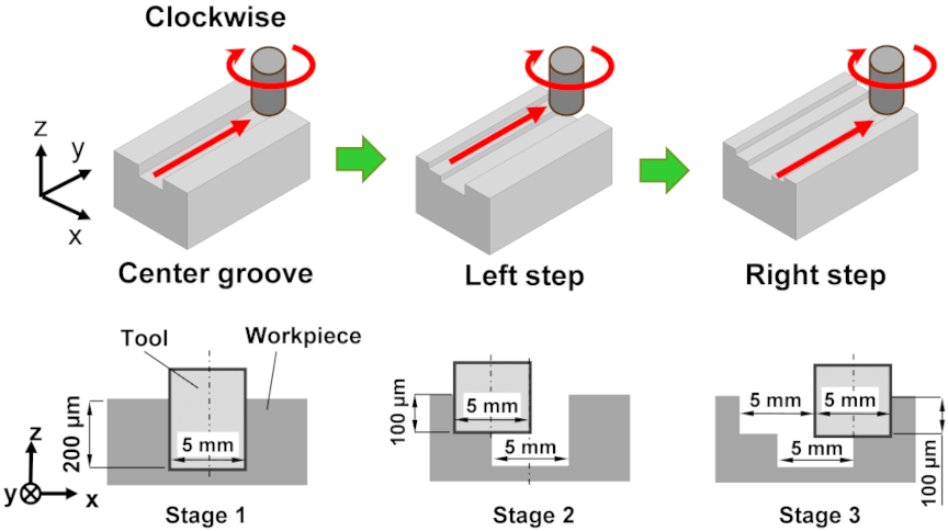
Fig. 3. Machining sequence of the target shape. The tool was fed relative to the stage at the center of a workpiece in the \(y\)-direction with a cut depth of 200 μm (Stage 1), and then the left step (Stage 2) and right step (Stage 3) were machined in the same manner at a depth of 100 μm.
3. Investigation of Burr Formation
3.1. Machining Using an End Mill with Rightward-Twisting Cutting Edges
First, the workpieces were machined to the target shape using an end mill with rightward-twisting cutting edges, as shown in Fig. 4(a). The cutting edge was twisted clockwise from top to bottom along the tool axis. This type of end mill is commonly used to machine metal workpieces. Hereafter, this end mill is referred to as the right-twist tool. In this experiment, the twist angle of the cutting edges was 30°. The cutting conditions were a feed rate of 0.20 mm/s and a rotation speed of 5,000 rpm.
As shown in Fig. 4(b), burrs were observed on the left edge of the 10-mm-wide groove at a cut depth of 100 μm. Moreover, the right edge contained large residues that covered the center. This result is attributed to removal of the workpiece such that the chips generated from the groove edges bounced out of the groove. Such chips are not broken by elastic deformation at the groove edges, which results in burrs and residues.
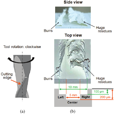
Fig. 4. Machining of the stepped groove using an end mill with rightward-twisting cutting edges. (a) Schematic of the right-twist tool. (b) Macroscopic photographs of the machined surface.
To investigate the burr formation shown in Fig. 4(b), Fig. 5 presents a photograph of the side view of a machined single groove. A single groove was formed as part of the process to obtain the stepped-groove target shape, corresponding to the center groove in Stage 1 in Fig. 3. However, this single groove was formed during the machining of a stepped groove, which is different from that shown in Fig. 4, although the machining process was the same. As shown in Fig. 5, burrs appear on both edges of the groove, because the chips remained on the edges as a result of elastic deformation of the edges in the outward direction of the groove. In particular, a large burr was generated on the right edge. When the left and right steps were subsequently machined, the burrs generated during the machining of the center groove did not break up and remained. As a result, the burrs, particularly on the right edge, are considered to have become so large that they cover the center groove, as shown in Fig. 4(b).
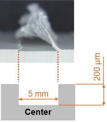
Fig. 5. Macroscopic photograph of a single groove machined using an end mill with rightward-twisting cutting edges. The groove corresponds to the center portion of the stepped groove.
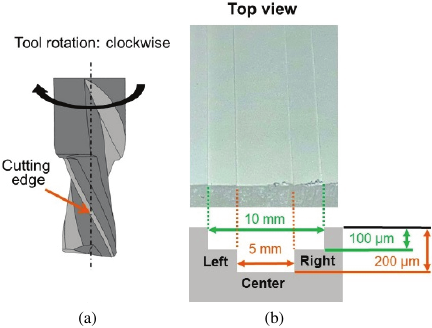
Fig. 6. Machining using an end mill with leftward-twisting cutting edges. (a) Schematic of the left-twisting tool. (b) Macroscopic photograph of a portion of the machined surface.
 (a)(b)
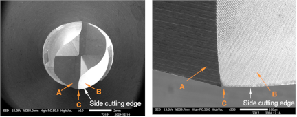
Fig. 7. SEM images of the left-twist tool before use. (a) Top and (b) enlarged views of the tool edge.
3.2. Machining Using an End Mill with Leftward-Twisting Cutting Edges
According to the experimental results shown in Fig. 4(b), we considered that a left-twist tool, whose cutting edges are twisted in the opposite direction to those of the right-twist tool, could reduce burr formation. We assumed that the left-twist tool would deform the chips inward into the groove where they would be broken up.
On the basis of this idea, the target shape was machined using a left-twist tool with a twist angle of 30°, as shown in Fig. 6(a). The shape of the left-twist tool was the same as that of the right-twist tool, except for the twist direction. The cutting conditions were identical to those used for machining with the right-twist tool. Fig. 6(b) shows a macroscopic photograph of a portion of the surface machined using the left-twist tool. As shown in Fig. 6(b), few burrs were observed on the surface, in contrast to the surface machined with the right-twist tool. These results demonstrated the effectiveness of the left-twist tool in preventing burr formation.
Figure 7 shows SEM images of the left-twist tool before use. Figs. 7(a) and (b) show the top and enlarged views of the tool edge, respectively. As shown in Fig. 7, no pronounced edge radius was observed, and the tool edge exhibited slight roughness. Therefore, the radii of the two side cutting edges of the tool at a position 100 μm from the tip (point C) in Fig. 7(b) were measured using a laser-type three-dimensional surface profiler (Mitaka Kohki, MLP-3SP) 26,27 and were found to be 2.6 μm and 3.8 μm.
In this experiment, the feed rate was 0.20 mm/s and the rotation speed was 5,000 rpm, corresponding to a feed per tooth of 1.2 μm. Thus, successful cutting was achieved even when the feed per tooth was smaller than the tool-edge radius. One possible reason is that even if the material undergoes elastic deflection, it may recover before the next tool passes. This can lead to an increase in the uncut chip thickness, which subsequently may be removed by the tool. Additionally, the slight roughness of the tool edge may have contributed to the cutting process.
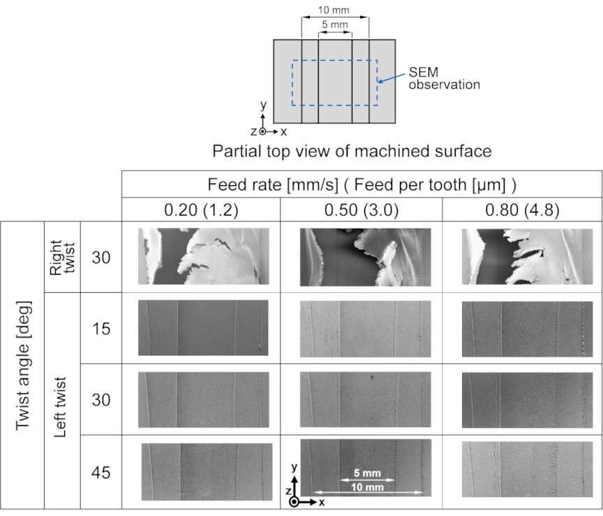
Fig. 8. SEM images of machined surfaces with various tools.
4. Effect of Twist Angle on Burr Formation
As described in the previous section, burr formation was effectively suppressed using the left-twist tool. In the preceding experiment, a tool with a twist angle of 30° was employed as the representative setting. Previous work by Shih et al. demonstrated that down-cut end mills (corresponding to left-twist tools) can achieve burr-free machining in the deep-groove milling of elastomers 20. Motivated by these findings, the influence of the twist angle on burr formation and dimensional accuracy in microstructured machining was investigated in the present study.
To this end, machining experiments were conducted using left-twist tools with twist angles of 15°, 30°, and 45°. For comparison, a right-twist tool with a twist angle of 30° was also employed. The feed rate of the workpiece was set to 0.20, 0.50, and 0.80 mm/s, while the tool rotational speed was kept constant at 5,000 rpm.
For machining with a right-twist tool, the SEM images of the machined surfaces are shown in the first row of Fig. 8, revealing burrs on the left and right edges. In each SEM image, the burr on the right edge was large and covered the center groove. The burr morphology changed little, even when the feed rate was changed in the range of 0.20 to 0.80 mm/s.
Subsequently, machining was performed using left-twist tools with various twist angles. The results are shown in the second, third, and fourth rows of Fig. 8. Each left-twist tool produced only a few burrs, if any. This result was attributed to the left-twist tool’s elastic bending of chips inward and downward along the groove, making them easier to break.
As shown in Fig. 8, the edges of the grooves and steps appear not to be straight. This apparent distortion is likely due to the low-magnification observations and is attributable to aberrations in the electron optics of the SEM device. It should be noted that the SEM images shown in Fig. 8 were acquired at low magnification, not to characterize the detailed edge morphology or individual burr shapes, but to evaluate the overall distribution and occurrence tendency of burr formation along the machined edge.
A closer look at Fig. 8 shows that burrs were scarcely generated by the left-twist tool at a low feed rate of 0.20 mm/s, regardless of the twist angle. This result is attributed to the reduced chip thickness owing to the low feed rate, which facilitates chip breakage. At a high feed rate of 0.80 mm/s, it was observed that slight burrs gradually appeared as the twist angle decreased. This tendency is likely due to a decrease in the cutting force directed downward into the groove, which, in turn, reduces chip breakage. Additionally, the burrs observed at the right edge were likely caused by down-cut end milling performed at that edge.
5. Evaluation of Dimension Accuracy of Machined Surfaces
The cross-sectional profiles of the machined surfaces were measured using a surface profiler. Large burrs were present on the surfaces machined with the right-twist tool, as described in Sections 3 and 4. These burrs were removed using tweezers before the measurement.
Figure 9 shows the cross-sectional profiles of the surfaces machined using a left-twist tool with a twist angle of 30°, a feed rate of 0.2 mm/s, and a rotational speed of 5,000 rpm. The figure presents overlaid profiles measured at different positions along the workpiece length: 6.25 mm, 12.5 mm (the center), and 18.75 mm from the side edge. As shown in Fig. 9, the profiles nearly coincide, indicating that machining was stable along the tool feed direction. This result also indicates that the distortion observed in the SEM images in Fig. 8 was caused by aberrations in the electron optics of the SEM device.
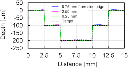
Fig. 9. Cross-sectional profiles of the surfaces machined using a left-twist tool at a feed rate of 0.2 mm/s and a rotational speed of 5,000 rpm. The profiles were measured at positions 6.25 mm, 12.5 mm, and 18.75 mm from the side edge.
Figure 10 shows the profiles of the surfaces machined at different feed rates using a left-twist tool with a twist angle of 30°, where the measuring position was at the center of the 25 mm length. The depth errors at the center of the profiles increased with the feed rate. Thus, we obtained the depth errors at the center of the central groove and at both side steps for each cutting condition, as shown in Fig. 11. Figs. 11(a), (b), and (c) show the depth errors at the center of the central groove, left step, and right step, respectively. As shown in the insets of Fig. 11, the positive sign on the vertical axis represents insufficient cut depth, and the negative sign represents overcutting. These figures reveal that when the feed rate was low, the depth errors tended to be small at the center of the central groove and at both side steps for any twist angle. As the feed rate increased, the depth errors increased and were affected by the twist angle.
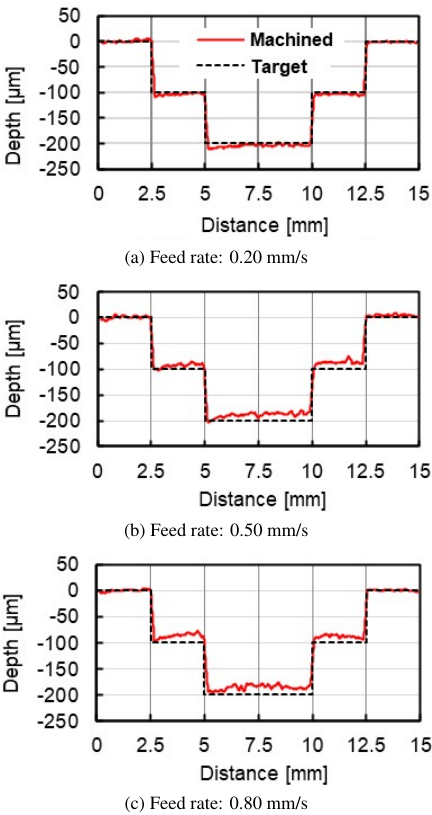
Fig. 10. Examples of cross-sectional profiles of the machined surfaces. The surfaces were machined at different feed rates using a left-twist tool with a twist angle of 30°.
The increase in the depth error with increasing feed rate, as shown in Fig. 11, can be explained as follows. When a cutting edge passes over a workpiece, the cutting force causes elastic deformation of the surface. A positive depth error is considered to result from the elastic recovery that occurs after the cutting edge has passed. On the basis of this interpretation, a higher feed rate increases the chip thickness, which in turn leads to a greater cutting force, and consequently, a larger amount of elastic recovery. Moreover, at all feed rates, the depth error tends to increase with the twist angle. This tendency is attributed to the increase in cutting force with increasing twist angle, which leads to a greater elastic deformation of the workpiece.
The depth-direction origin of the machining was determined by placing a block gauge on the workpiece and setting the origin to the point where electrical contact was established between the block gauge and the tool. Consequently, the origin may be set with the workpiece slightly indented, which could lead to overcutting near the origin. Therefore, at a low feed rate (0.2 mm/s), the chip thickness becomes small and the material’s elastic recovery is reduced, which may make the influence of overcutting due to the origin-setting method more apparent.
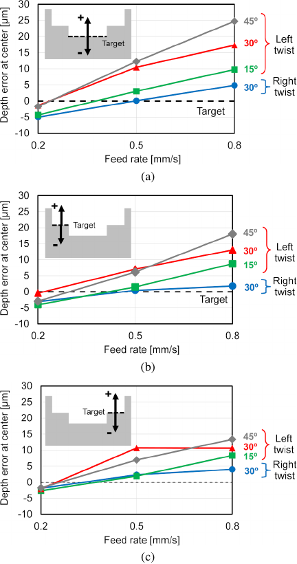
Fig. 11. Depth errors at the centers of the (a) central groove, (b) left step, and (c) right step for each twist angle.
6. Conclusions
We investigated the milling of microstructures, specifically stepped micro-grooves with submillimeter depths, on a nitrile rubber surface. The experiments were conducted using an NC milling machine and cemented carbide end mills with different twist directions and angles. We compared the left-twist and right-twist tools and evaluated the effects of twist angle and feed rate on burr formation and dimensional accuracy.
Burr formation was significantly suppressed using a left-twist tool. In particular, nearly burr-free machining was achieved when either a large twist angle or low feed rate was applied. The depth errors of the grooves were reduced under the conditions of a small twist angle or low feed rate. A possible reason for the deterioration in the depth error with greater twist angles and higher feed rates is the elastic deformation of the workpiece caused by an increase in the vertical cutting force. These findings provide important guidelines for the small-lot, high-mix production of rubber products with microstructured surfaces. This study represents a fundamental first step toward the machining-based fabrication of complex microstructured geometries on rubber surfaces, addressing not only burr suppression but also dimensional accuracy.
In the present study, the discussion of the mechanisms of burr formation and suppression was limited to qualitative considerations. In future work, a more detailed mechanistic understanding will be pursued, based on direct observations of the chip flow using a high-magnification, high-speed camera, systematic analyses of the chip morphology, measurements of the cutting forces, and cutting simulations. Furthermore, we plan to extend this study to the machining of finer and more complex microstructured geometries using smaller-diameter tools, which will enable the fabrication of more intricate rubber microstructures.
Acknowledgments
We are grateful to Mr. Makoto Tsuruta, Dr. Masashi Yamaguchi, and Dr. Shogo Wada of the Bridgestone Corporation for useful discussions. We are also grateful to Mr. Takao Tsukamoto of Mitaka Kohki Corporation and Mr. Kazuyuki Yagi of Ryokosha Corporation for measuring the edge radius of the milling tool. We thank Mr. Yuta Tobe of the Chiba Institute of Technology for assisting with the experiments.
- [1] M. K. Raj and S. Chakraborty, “PDMS microfluidics: A mini review,” J. Appl. Polym. Sci., Vol.137, Issue 27, 2020. https://doi.org/10.1002/app.48958
- [2] Y. Hirai, R. Tamura, S. Emoto, M. Shimomura, Y. Matsuo, T. Okamatsu, and T. Arita, “Superhydrophobic microstructure imprinted rubber sheet by hot vulcanization press,” Nippon Gomu Kyokaishi, Vol.90, pp. 277-282, 2017 (in Japanese). https://doi.org/10.2324/gomu.90.277
- [3] C. Fukuda, K. Takahashi, Y. Nishimura, K. Sunada, and K. Ozaki, “Wettability and friction property of rubber sheet transferred from porous plating with microstructural surface,” Nippon Gomu Kyokaishi, Vol.95, pp. 8-12, 2022 (in Japanese). https://doi.org/10.2324/gomu.95.8
- [4] Bridgestone Corporation Website, “Tires are important not only for performance but also for design, Let us introduce Bridgestone’s LUXBLACK®,” 2020 (in Japanese). https://www.bridgestone.co.jp/blog/2020082401.html [Accessed December 18, 2025].
- [5] K. Kato, M. Yamaguchi, T. Miyazono, and M. Tsuruta, “Enhancement of tire durability by considering air flow field,” Tire Science and Technology, Vol.37, No.2, pp. 103-121, 2009. https://doi.org/10.2346/1.3130986
- [6] M. Tsuruta, “Run-flat tire technology,” Nippon Gomu Kyokaishi, Vol.85, pp. 193-197, 2012 (in Japanese). https://doi.org/10.2324/gomu.85.193
- [7] Bridgestone Corporation Website, “Cooling fins for tire cooling.” https://tire.bridgestone.co.jp/runflat/s001rft/ [Accessed December 18, 2025].
- [8] Panasonic Industry Corporation Website, “Pressure-Sensitive Sensing Devices, Multifunctionality Enabled by Conductive Micropillars Wide Applications in Mobile Devices and Robotics,” (in Japanese). https://www.panasonic.com/jp/industry/news/focus/pressure-sensing-device.html [Accessed December 18, 2025].
- [9] A. I. Shallan, P. Smejkal, M. Corban, R. M. Guijt, and M. C. Breadmore, “Cost-effective three-dimensional printing of visibly transparent microchips within minutes,” Analytical Chemistry, Vol.86, No.6, pp. 3124-3130, 2014. https://pubs.acs.org/doi/10.1021/ac4041857
- [10] J. Wu, H. Fang, J. Zhang, and S. Yan, “Modular microfluidics for life sciences,” J. Nanobiotechnology, Vol.21, Article No.85, 2023. https://doi.org/10.1186/s12951-023-01846-x
- [11] M. Jin and M. Murakawa, “High-speed milling of rubber (1st report) – Fundamental experiments and considerations for improvement of work accuracy –,” J. Jpn. Soc. Precis. Eng., Vol.64, Issue 6, pp. 897-901, 1998 (in Japanese). https://doi.org/10.2493/jjspe.64.897
- [12] N. Takahashi and J. Shinozuka, “Contributions of high-speed cutting and high rake angle to the cutting performance of natural rubber,” Int. J. Automation Technol., Vol.8, No.4, pp. 550-560, 2014. https://doi.org/10.20965/ijat.2014.p0550
- [13] J. Shinozuka and Y. Imakama, “Effect of parallel micro-grooves fabricated on the rake and flank faces on the improvement of the cutting performance of low-rigidity elastomers,” J. Jpn. Soc. Precis. Eng., Vol.83, No.7, pp. 679-686, 2017 (in Japanese). https://doi.org/10.2493/jjspe.83.679
- [14] K. Teramoto, T. Kunishima, and H. Matsumoto, “Analysis of cutting force in elastomer end-milling,” Int. J. Automation Technol., Vol.11, No.6, pp. 958-963, 2017. https://doi.org/10.20965/ijat.2017.p0958
- [15] A. Chainawakul, K. Teramoto, and H. Matsumoto, “Statistical modelling of machining error for model-based elastomer end-milling,” Int. J. Automation Technol., Vol.15, No.6, pp. 852-859, 2021. https://doi.org/10.20965/ijat.2021.p0852
- [16] K. Mishima, Y. Kakinuma, and T. Aoyama, “Pre-deformation-assisted cryogenic micromachining for fabrication of three-dimensional unique micro channels,” J. Adv. Mech. Des. Syst. Manuf., Vol.4, Issue 5, pp. 936-947, 2010. https://doi.org/10.1299/jamdsm.4.936
- [17] V. G. Dhokian, S. T. Newman, P. Crabtree, and M. P. Ansell, “A process control system for cryogenic CNC elastomer machining,” Robot. Comput.-Integr. Manuf., Vol.27, Issue 4, pp. 779-784, 2011. https://doi.org/10.1016/j.rcim.2011.02.006
- [18] Y. Kakinuma, S. Kidani, and T. Aoyama, “Ultra-precision cryogenic machining of viscoelastic polymers,” CIRP Annals, Vol.61, Issue 1, pp. 79-82, 2012. https://doi.org/10.1016/j.cirp.2012.03.039
- [19] P. Maurya, G. S. Vijay, K. C. Raghavendra, and B. Shivamurthy, “Cryogenic machining of elastomers: A review,” Mach. Sci. Technol., Vol.25, Issue 3, pp. 477-525, 2021. https://doi.org/10.1080/10910344.2021.1903923
- [20] A. J. Shih, M. A. Lewis, and J. S. Strenkowski, “End milling of elastomers – Fixture design and tool effectiveness for material removal,” J. Manuf. Sci. Eng., Vol.126, pp. 115-123, 2004. https://doi.org/10.1115/1.1616951
- [21] A. J. Shih, M. A. Lewis, and J. S. Strenkowski, “Chip morphology and forces in end milling of elastomers,” J. Manuf. Sci. Eng., Vol.126, Issue 1, pp. 124-130, 2004. https://doi.org/10.1115/1.1633276
- [22] J. Luo, H. Ding, and A. J. Shih, “Induction-heated tool machining of elastomers – Part 1: Finite difference thermal modeling and experimental validation,” Mach. Sci. Technol., Vol.9, Issue 4, pp. 547-565, 2005. https://doi.org/10.1080/10910340500398225
- [23] J. Luo, H. Ding, and A. J. Shih, “Induction-heated tool machining of elastomers – Part 2: Chip morphology, cutting forces, and machined surfaces,” Mach. Sci. Technol., Vol.9, Issue 4, pp. 567-588, 2005. https://doi.org/10.1080/10910340500398233
- [24] K. Miura and A. Nose, “Point autofocus instruments,” R. Leach (Ed.), “Optical measurement of surface topography,” pp. 107-129, Springer, 2011. https://doi.org/10.1007/978-3-642-12012-1_6
- [25] K. Miura, “Surface topography measurement of optics devices with a point autofocus profiling,” J. Soc. Instrum. Control Eng., Vol.50, No.2, pp. 138-142, 2011 (in Japanese). https://doi.org/10.11499/sicejl.50.138
- [26] K. Miura, T. Matsuba, T. Tsukamoto, H. Hirose, and H. Kotajima, “Development and practicality of a point autofocus probe ultra-precision 3D whole circumference measuring instrument (MLP-2SP),” J. Jpn. Soc. Precis. Eng., Vol.81, No.2, pp. 113-116, 2015 (in Japanese). https://doi.org/10.2493/jjspe.81.113
- [27] K. Miura, A. Nose, H. Suzuki, and M. Okada, “Cutting tool edge and textured surface measurements with a point autofocus probe,” Int. J. Automation Technol., Vol.11, No.5, pp. 761-765, 2017. https://doi.org/10.20965/ijat.2017.p0761
This article is published under a Creative Commons Attribution-NoDerivatives 4.0 Internationa License.