Research Paper:
Study on a Dual-Motor Synchronous Drive System Based on a TAB Converter
Yiying Wang*, Mingxian Liu*, Dongyi Zhang*, Chen Liu*, Yang Liu**,†, and Jie Wu***
*Hebei University of Engineering
No.19 Taiji Road, Congtai District, Handan, Hebei 056000, China
**China University of Mining and Technology
Beijing, China
†Corresponding author
***Anyang Institute of Technology
Anyang, China

This study addresses the limitations of conventional frequency converter-driven dual-motor systems, such as excessive space occupancy and power imbalance between the front and rear motors. An integrated dual-motor synchronous drive system is presented, integrating voltage conversion and variable-frequency functionality. Furthermore, this study proposes two cross-coupling synchronization strategies: a speed-loop compensated proportional integral derivative (PID) control and torque-loop compensated PID control. In accordance with the system architecture, phase-shift control for the triple active bridge converter and direct torque control for the motors are investigated. Under unbalanced load conditions, the proposed speed-loop compensated PID cross-coupling method replaces the conventional single-gain cross-coupling controller, significantly improving speed synchronization accuracy. The torque-loop compensated PID cross-coupled control further enhances synchronization performance. Both simulation and experimental results validate the accuracy and effectiveness of the proposed control strategies.
1. Introduction
Ongoing advances in power electronics technology have resulted in AC frequency converters becoming the standard solution for motor control. In recent years, multi-motor cooperative drive systems have gained traction in several sectors, including industrial automation, electric vehicles, and engineering machinery [1–4].
Conventional dual-motor drive solutions, which employ two independent inverters for separate controls, exhibit several limitations. The use of independent drive systems increases both equipment volume and cost, complicates system wiring, and increases difficulty in fault diagnosis. These factors make it challenging to meet the stringent requirements for compactness and operational reliability in applications such as engineering machinery and precision manufacturing 5,6. However, the decentralized drive approach is prone to synchronization errors between motors because of control signal delays, resulting in uneven load distribution, overloading of individual motors, and compromised overall system reliability 7,8. Therefore, achieving speed balance in dual-motor systems is critical. Current research in this domain primarily explores parallel control, master-slave control 9, and cross-coupling control 10 strategies.
Reference 11 proposed a dual-inverter system with a common DC bus to drive two motors in the traction mechanism of a coal mining machine. The system comprises an AC-DC rectifier module and two DC-AC inverter modules, which share a common DC bus. Voltage transformation is achieved using a power-frequency transformer, which is installed separately and occupies considerable space. Liu et al. proposed a three-phase high-frequency isolated dual-PWM variable frequency speed regulation system with a three-level topology 12, employing a dual active bridge (DAB) converter to replace the DC link in conventional frequency converters, effectively reducing the overall volume of a single-motor drive system. However, this configuration cannot be directly applied to dual-motor drives.
Xiao et al. implemented a master-slave control strategy for a dual-motor system in a belt conveyor 13 to achieve a coordinated dual-motor drive. Qin et al. proposed a current-loop cross-coupling control method to reduce the speed difference between two motors in a large excavator rotary system 14. Based on a unified speed-loop model for dual motors, Geng et al. proposed a dual-motor active disturbance rejection cross-coupling speed synchronization control strategy that demonstrated optimal performance in high-power industrial automation applications 15. Zhang et al. proposed a novel dual-motor coupled drive system for electric vehicles, improving energy efficiency across various driving conditions 16.
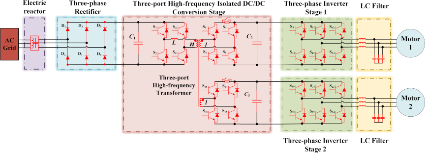
Fig. 1. Topology diagram of the dual-motor synchronous drive system.
To address these issues, this study investigates a dual-motor variable-frequency speed regulation system. First, a coordinated dual-motor drive system topology is proposed, and the power transfer characteristics of a triple active bridge (TAB) converter are analyzed. Based on this analysis, a single-phase-shift (SPS) control strategy for the three-port converter and direct torque control (DTC) for the motors are studied to achieve an integrated design for a dual-motor drive. To further enhance the synchronization performance of dual motors, speed- and torque-loop-compensated PID cross-coupling control strategies are introduced. Compared with the traditional single-gain cross-coupling control in the speed loop, the proposed speed-loop-compensated PID control strategy significantly improves the speed synchronization accuracy. The torque-loop-compensated PID control strategy further enhances the synchronization response speed and torque-control accuracy of the system. Finally, the effectiveness and correctness of the proposed control strategies are verified via simulations and experiments.
2. Topology Design of Dual-Motor Drive System
The circuit topology of the dual-motor coordinated drive system is illustrated in Fig. 1. It comprises four primary components arranged sequentially from left to right along the power flow path: a three-phase rectifier input stage, TAB converter, and two three-phase inverter stages.
The three-phase rectifier stage employs a bridge rectifier circuit composed of six diodes (D1–D6). To enhance the system performance, a reactor and precharge circuit are added at the front end of the rectifier bridge. This design suppresses harmonic currents, thereby improving the reliability and stability of the system. The TAB converter comprises three H-bridge modules (S1–S4, S5–S8, and S15–S18) connected to a high-frequency transformer with three windings. Depending on the number of input and output ports, the operating modes of the TAB converter can be classified as single-input dual-output and dual-input single-output. In this study, a single-input dual-output mode was adopted. Each three-phase inverter stage comprises six power-switching devices (S9–S14 and S19–S24), and is responsible for converting DC power into three-phase AC power. To improve the quality of the output power, an LC filter is connected between the output of the inverter and the motor load to suppress harmonic components.
3. Analysis of Topological Control Strategies at all Levels
3.1. Control Strategies for Three-Phase Rectifier Stages
The input stage comprises only six diodes and one filter capacitor. The rectifier circuit converts the three-phase alternating current into a pulsating direct current via natural commutation of the diodes. Capacitor C smooths the output voltage and reduces ripple.
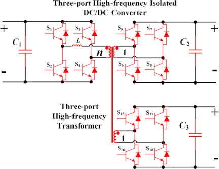
Fig. 2. TAB converter topology diagram.
3.2. Control Strategy of TAB Converter
A TAB converter can be considered an extended structure of a DAB converter 17, as shown in Fig. 2. Compared with the DAB converter, the TAB converter features more ports and a higher control complexity. Inspired by prior research on DAB converters 18, this study adopts an SPS control strategy that regulates the magnitude and direction of the power transferred between ports by adjusting the phase lead or lag between the square-wave voltages of the primary and secondary sides. Under SPS control, the gate drive signals of the switching devices in the TAB converter as well as the square-wave voltage and current waveforms of each port are illustrated in Fig. 3. Using the square-wave voltage of port 1 as the phase reference, the phase-shift ratios of ports 2 and 3 relative to port 1 are denoted as \(D_{12}\) and \(D_{13}\), respectively. The relationship between the phase shift angles and the phase shift ratios can be expressed as \(\emptyset_{12}=\pi {D}_{12}\) and \(\emptyset_{13}=\pi {D}_{13}\).
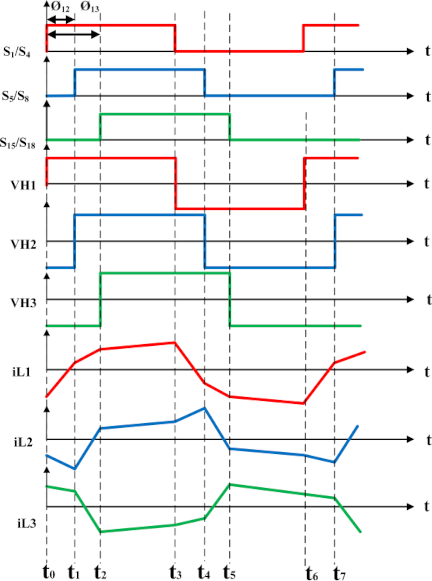
Fig. 3. Each port drive signal of the TAB converter, a voltage square wave plus the corresponding current wave.
When the hardware parameters of the converter (transformer winding ratio, frequency, inductance, and capacitance) remain unchanged, the power transfer capability of each port is controlled by two independent variables, \(D_{12}\) and \(D_{13}\). In other words, the phase-shift ratio between each pair of ports can regulate both the magnitude and direction of the power flow. The corresponding control block diagram is shown in Fig. 4.
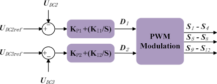
Fig. 4. Three-port DC/DC control block diagram.
Because the maximum power transfer point of a DAB converter is achieved at \({D}=0.5\), by analogy, the phase shift ratios corresponding to the maximum power transfer of the TAB converter are \({D}_{12}= 0.5\), \({D}_{13}=0.5\), and \({D}_{23}=0\), as given in Eq. \(\eqref{eq:1}\), which expresses the maximum power transfer for each port of the three-port DC/DC converter under a single-phase-shift modulation.
3.3. Three-Phase Inverter Stage Control Strategy
The output stage is divided into two groups. To control each three-phase inverter, a DTC strategy based on space vector pulse width modulation (SVPWM) was adopted. DTC is a novel variable-frequency speed regulation technology developed based on field-oriented control (FOC). This technique departs from the decoupling principle of vector control by shifting the control basis from rotor flux orientation to stator flux orientation, thereby enabling a faster dynamic torque response. By replacing traditional switching tables and bang–bang controllers with SVPWM technology, the issue of low inverter switching frequency in conventional DTC can be effectively addressed, achieving a constant switching frequency and thus suppressing the torque ripple. The direct torque control system primarily comprises a flux linkage and torque calculation module, speed regulation module, flux linkage and torque hysteresis regulation module, coordinate transformation module, and SVPWM modulation module. The system control block diagram is shown in Fig. 5.
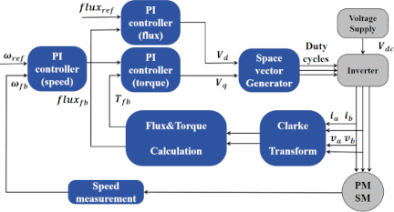
Fig. 5. Block diagram of direct torque control system based on SVPWM.
To calculate the flux and torque, coordinate transformation must be performed. The transformation of current and voltage from the three-phase stationary \(abc\) coordinate system to the two-phase \(\alpha\beta\) coordinate system is known as Clarke transformation. The transformation matrix is expressed by Eq. \(\eqref{eq:3}\).
The Park transformation is the transformation from the two-phase stationary \(\alpha\beta\) coordinate system to the two-phase rotating \(dq\) coordinate system, and its transformation matrix is shown in Eq. \(\eqref{eq:4}\).
The inverse Park transformation matrix for transforming \(i_d\) and \(i_q\) in the \(dq\) rotating coordinate system back to \(i_{\alpha}\) and \(i_{\beta}\) in the stationary \(\alpha\beta\) coordinate system is shown in Eq. \(\eqref{eq:5}\).
Herein, \(\theta\) denotes the angle between the two-phase rotating coordinate system and the horizontal axis of the two-phase stationary coordinate system. The voltage transformation formula follows the same approach as that of the current transformation, with the only modification being the substitution of current with voltage.
The following equations describe the flux estimation based on the rotor position in the \(\alpha-\beta\) reference frame:
The following equations describe the torque estimation in the \(\alpha-\beta\) reference frame:
In the equations, \(\psi\) denotes the rotor flux of the permanent magnet synchronous motor (PMSM) (in units of weber). \(\psi_{\alpha}\) represents the rotor flux on the \(\alpha\)-axis of the \(\alpha-\beta\) reference frame. \(\psi_{\beta}\) represents the rotor flux on the \(\beta\)-axis of the \(\alpha-\beta\) reference frame. \(\psi_{\textit{PM}}\) represents the magnetic linkage of the PMSM. \(L_s\) represents the stator inductance of the PMSM (in units of henry). \(i_{\alpha}\) represents the motor current on the \(\alpha\)-axis of the \(\alpha-\beta\) reference frame (in units of ampere). \(i_{\beta}\) represents the motor current on the \(\beta\)-axis of the \(\alpha-\beta\) reference frame (in units of ampere). \(\theta\) represents the rotor position (in units of radians); \(T\) represents the rotor torque (in units of Nm); and \(p\) represents the number of pole pairs of the motor.
The SVPWM employs the principle of average voltage equivalence. During each switching cycle, the reference voltage is generated based on its sector by appropriately modulating the dwell times of the two effective voltage vectors in that sector, with the residual time interval assigned to a zero voltage. For a PMSM, if the stator winding resistance is neglected, the trajectory of the fixed point of the voltage vector corresponds to the trajectory of the stator flux linkage.
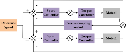
Fig. 6. Speed-loop PID cross-coupling control block diagram.
3.4. Design of Dual-Motor Synchronous Control System
Based on the control structure illustrated in Fig. 5, a speed-loop PID cross-coupling synchronization controller was constructed, as shown in Fig. 6. This controller takes the speed synchronization error between the two motors as its input and outputs the adjustment signal to the input of the speed loop, thereby achieving synchronous speed regulation of the dual motors.
Applying the adjustment signal from the PID cross-coupling synchronization controller to the input of the torque loop constitutes a torque-compensated PID cross-coupling control strategy. This approach regulates speed based on the rapid feedback of the torque loop, further enhancing both the synchronization performance and dynamic response speed of the system under unbalanced load disturbances. The corresponding system structure is shown in Fig. 7. By directly adjusting the torque loop, speed synchronization control achieves enhanced immediacy and improves the accuracy of the response of the two motors to load torque variations. Simulations and experimental verifications to validate the effectiveness of the proposed control strategies are presented in the following sections.
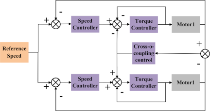
Fig. 7. Torque-loop PID cross-coupling control block diagram.
4. Simulation Analysis of the Entire Machine System
Based on the operating principles of the aforementioned system, a simulation model of the dual-motor coordinated drive system was developed using MATLAB/Simulink, and a system-level simulation analysis was conducted. The system was supplied by a three-phase AC power source, and the detailed simulation parameters are listed in Table 1.
Table 1. Simulation circuit parameters.

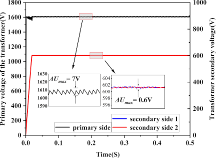
Fig. 8. Voltage of each port of the three-port DC converter.
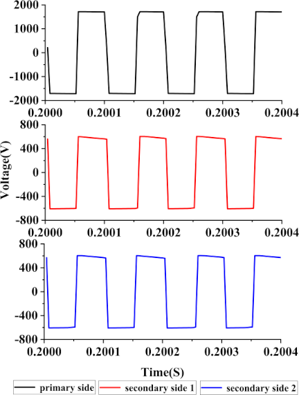
Fig. 9. AC voltage at each port of the high-frequency transformer.
Table 2. Operating conditions for simulation.

Table 3. Cross-coupling control parameters.

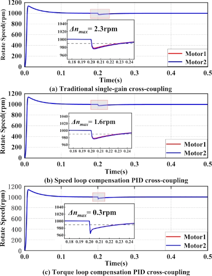
Fig. 10. Simulation curve of dual-motor speed under single-side loading condition.
Figure 8 shows the DC voltage waveforms at each port of the TAB converter. The primary side voltage was obtained after uncontrolled rectification and capacitor filtering. The voltages at the secondary ports 1 and 2 serve as inputs for inverters 1 and 2, respectively, which drive the motors. Fig. 9 shows the AC voltage waveforms at the ports of the three-port high-frequency transformer. Under the regulation of the SPS control strategy, the secondary voltages rapidly reached a steady state with significantly reduced voltage fluctuations.
Three simulation conditions were established: unilateral load increase, sudden unilateral load change, and unilateral load decrease. The specific speed setpoints and time nodes for the load torque variations for each condition are provided in Table 2, and the cross-coupling control parameters used in the simulations are listed in Table 3.
To quantitatively evaluate the performance of dual-motor synchronous drive, two core performance indicators are (1) maximum synchronous speed deviation \(\Delta max\), i.e., \(\Delta\textit{max}=\textit{max}\{\vert n_1-n_2\vert\}\), which characterizes the speed synchronization accuracy of the dual motors and (2) speed response time, which is defined as the time required for the motor speed to recover to within \(\pm 1\)% of the rated speed after deviating from the steady state owing to load disturbance. The rated speed in this study is 1000 rpm, corresponding to a tolerance band of 990–1010 rpm. Combining the simulation curves of the three typical operating conditions, the synchronization accuracy and response time of the system were analyzed in detail.
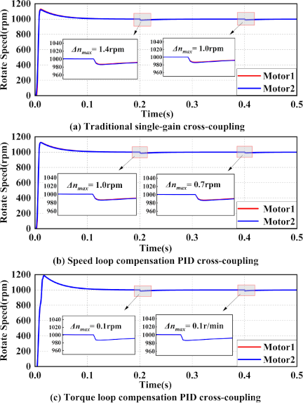
Fig. 11. Simulation curve of dual-motor speed under load sudden change conditions.
Figure 10 shows that under the unilateral loading condition, the torque loop compensation method exhibits the smallest synchronization error among the three methods, at only 0.3 rpm. The synchronization error of the speed loop compensation method ranks second, at 1.6 rpm; and the speed synchronization error of the traditional single-gain method is the largest, reaching 2.3 rpm. In terms of response time, the speed response times of the conventional single-gain control and the speed loop compensation control are consistent, both 35 ms, with no significant difference between them. By contrast, the torque-loop compensation control marginally reduced the response time to 31 ms via rapid adjustment of the torque feedback, which was shortened by 11.4% compared with the conventional control method.
Figure 11 presents the speed response curves of the three cross-coupled control methods (traditional single-gain, speed-loop compensation, and torque-loop compensation) under sudden load change conditions. The results indicate that in the first stage of the load sudden change, the synchronous speed deviations of the three methods are 1.4, 1.0, and 0.1 rpm, respectively.
However, in the second stage, the corresponding values were 1.0, 0.7, and 0.1 rpm, respectively. The torque-loop compensation method achieved the smallest maximum synchronous speed deviation in both stages, thereby exhibiting the highest speed synchronization accuracy.
Figure 12 shows the speed response curves of the three cross-coupled control methods (traditional single-gain, speed-loop compensation, and torque-loop compensation) under unilateral load reduction conditions. The advantage of the torque loop compensation control in synchronization accuracy is consistently maintained, with a synchronous speed deviation of only 0.3 rpm, which is significantly lower than that of the speed loop compensation control (1.6 rpm) and the traditional single-gain control (2.3 rpm). Under these operating conditions, the speed response times of the three control strategies were maintained at 35 ms.
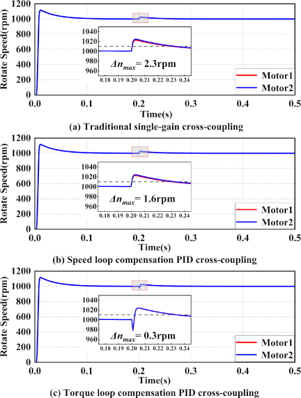
Fig. 12. Simulation curve of dual-motor speed under load reduction condition.
5. Experimental Validation of the Overall System
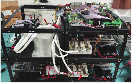
Fig. 13. Dual-motor synchronous drive experimental platform.
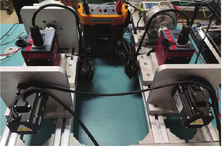
Fig. 14. Dual-motor test platform.
To verify the practical feasibility and engineering effectiveness of the proposed dual-motor synchronous-drive system and control strategy, an experimental platform was constructed using DSP28377D as the core controller, as shown in Figs. 13 and 14. The tests were conducted under three typical operating conditions: unilateral loading, sudden load change, and unilateral load reduction. The core evaluation indicators include the maximum synchronous speed deviation and speed response time. A detailed analysis of the test results is presented as follows. The detailed experimental parameters are listed in Table 4.
Table 4. Experimental platform circuit parameters.

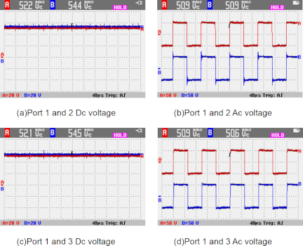
Fig. 15. Waveform of TAB converter.
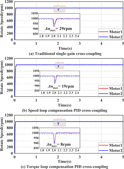
Fig. 16. Speed curve of dual motors under increased load conditions.
In Figs. 15(a) and (c), the red curves represent the voltage at Port 1 of the TAB converter, whereas the blue curves in Figs. 15(a) and (c) correspond to the voltages at Ports 2 and 3, respectively. Similarly, in Figs. 15(b) and (d), the red curves indicate the voltage at Port 1 of the three-port transformer, and the blue curves in Figs. 15(b) and (d) represent the voltages at Ports 2 and 3, respectively.
Under the unilateral loading condition, Motor 2 serves as the loaded motor, with a load of 5 N\({\cdot}\)m applied during operation, while Motor 1 remains unloaded. The experimental results are shown in Fig. 16. Traditional single-gain control exhibited the largest synchronous speed deviation, reaching 29 rpm. The speed-loop compensation control reduced the synchronous speed deviation to 19 rpm, representing a 34.5% reduction compared with traditional control. The torque-loop compensation control achieved the smallest synchronous speed deviation of only 8 rpm, which is a 72.4% reduction compared with the traditional control and a 57.9% reduction compared with speed-loop compensation control, demonstrating the most prominent advantage in synchronization accuracy. In terms of speed response time, traditional single-gain control yielded 56 ms, speed loop compensation control yielded 39 ms, and torque loop compensation control yielded 37 ms. All these experimental values exhibited a high degree of consistency with the simulation results.
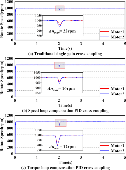
Fig. 17. Speed curve of dual motors under sudden load changes.
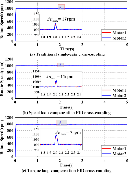
Fig. 18. Speed curve of dual motors under reduced load conditions.
In the load sudden change experiment, Motor 1 is consistently loaded with 5 N\({\cdot}\)m, while the load of Motor 2 suddenly changes from the initial 2 N\({\cdot}\)m to 5 N\({\cdot}\)m. The experimental results are shown in Fig. 17. Under this sudden load change, the traditional single-gain control method exhibited suboptimal performance with low-speed synchronization accuracy, yielding a synchronous speed deviation of 17 rpm. The synchronous speed deviation of the torque loop compensation control was 6 rpm, which is smaller than that of the speed loop compensation control (12 rpm). Consequently, the torque-loop compensation method achieved the highest speed synchronization accuracy.
In the unilateral load reduction experiment, both Motor 1 and Motor 2 are initially loaded with 5 N\({\cdot}\)m, and the load of Motor 2 is subsequently reduced to 0 N\({\cdot}\)m. The experimental results are presented in Fig. 18.
The synchronous speed deviations of the three methods were 17, 11, and 7 rpm for the traditional single-gain control, speed loop compensation control, and torque loop compensation control, respectively. Among these, the traditional single-gain control exhibited the largest synchronous speed deviation, whereas the torque loop compensation method achieved the smallest deviation. The corresponding speed response times for the three methods are 39, 39, and 41 ms, respectively.
6. Conclusion
This study introduced a dual-motor drive system integrating voltage conversion and a variable-frequency drive based on power electronics technology and an innovative TAB converter structure. The system consists of a three-phase rectifier, TAB converter, and two three-phase inverter stages. The three-phase rectifier stage implements uncontrolled rectification using diodes. The TAB converter is characterized by a single-input dual-output configuration and manages power transmission via phase-shift control. The output stage is controlled employing the DTC-SVPWM strategy. This achieves a dual-motor drive while reducing the system volume. To minimize the speed difference between the two motors in a dual-motor synchronous drive, two PID cross-coupled control strategies are proposed: speed-loop compensation-based PID cross-coupled control and torque-loop compensation-based PID cross-coupled control.
Experimental and simulation results demonstrate that the proposed torque loop compensation-based PID cross-coupled control strategy restricts the steady-state speed deviation of the dual motors to within 12 rpm (experimental value), achieving a 45.5%–72.4% reduction compared with the traditional single-gain control. Furthermore, the proposed strategy shortens the speed response time by 33.9% relative to the traditional control. This is followed by speed-loop compensation-based PID control, which realizes a 27.3%–35.3% reduction in the maximum synchronous speed deviation and a 30.3% decrease in the speed response time. In summary, both compensation strategies can effectively enhance the speed synchronization accuracy and dynamic tracking capability of a dual-motor system. They address the key issue of synchronization inaccuracy in traditional systems and also ensure the stability of dynamic responses, providing a feasible solution for the topology design and control optimization of multi-motor integrated drive systems.
Acknowledgments
This study was supported by the Science Research Project of the Hebei Education Department (No. CXY2023002).
- [1] W. Wu, Q. Chen, X. Zhu, Q. Lu, F. Zhao, J. Yao, and L. Gao, “Design and analysis of a new permeability-modulated interior permanent-magnet synchronous machine,” IEEE Trans. on Magnetics, Vol.57, No.2, Article No.8103105, 2021. https://doi.org/10.1109/TMAG.2020.3015784
- [2] C. Wen, J. Liu, W. Wang, J. Liu, Z. Zhao, and J. Liu, “Research on improved permanent magnet linear synchronous motor for direct-drive application,” IEEE Trans. on Magnetics, Vol.55, No.10, Article No.8107007, 2019. https://doi.org/10.1109/tmag.2019.2923952
- [3] S. Wang, L. Tao, Q. Chen, J. Na, and X. Ren, “USDe-based sliding mode control for servo mechanisms with unknown system dynamics,” IEEE/ASME Trans. on Mechatronics, Vol.25, No.2, pp. 1056-1066, 2020. https://doi.org/10.1109/TMECH.2020.2971541
- [4] X. Lin, Z. Lin, and S. Wei, “Multi-objective optimized driving strategy of dual-motor EVs using NSGA-II as a case study and comparison of various intelligent algorithms,” Applied Soft Computing J., Vol.111, Article No.107684, 2021. https://doi.org/10.1016/J.ASOC.2021.107684
- [5] X. Yan, S. Ge, H. Zu, J. Bao, G. Chang, L. Zhang, and H. Li, “Permanent magnet intelligent drive system and control strategy for belt conveyors,” J. of China Coal Society, Vol.45, No.6, pp. 2116-2126, 2020 (in Chinese). https://doi.org/10.13225/j.cnki.jccs.zn20.0345
- [6] G. Shi, P. Qiao, D. Sang, S. Wang, and M. Song, “Synchronous and fault-tolerance control for dual-motor steer-by-wire system of commercial vehicle,” Proc. of the Institution of Mechanical Engineers, Part D: J. of Automobile Engineering, Vol.238, No.7, pp. 1964-1980, 2024. https://doi.org/10.1177/09544070231154961
- [7] N. Panda, B. Das, A. Chakrabarti, P. R. Kasari, A. Bhattacharya, and D. Chatterjee, “A new grid interactive 11-level hybrid inverter topology for medium-voltage application,” IEEE Trans. on Industry Applications, Vol.57, No.1, pp. 869-881, 2021. https://doi.org/10.1109/TIA.2020.3040204
- [8] Z. Wang, J. Zhou, and G. Rizzoni, “A review of architectures and control strategies of dual-motor coupling powertrain systems for battery electric vehicles,” Renewable and Sustainable Energy Reviews, Vol.162, Article No.112455, 2022. https://doi.org/10.1016/j.rser.2022.112455
- [9] A. Cordeiro, J. F. M. Manuel, and V. F. Pires, “Performance of synchronized master-slave closed-loop control of AC electric drives using real time motion over ethernet (RTMoE),” Mechatronics, Vol.69, Article No.102400, 2020. https://doi.org/10.1016/j.mechatronics.2020.102400
- [10] Z. Li, Q. Zhang, J. An, X. Liu, and H. Sun, “Cross-coupling control method of the two-axis linear motor based on second-order terminal sliding mode,” J. of Mechanical Science and Technology, Vol.36, No.3, pp. 1485-1495, 2022. https://doi.org/10.1007/S12206-022-0235-2
- [11] H. Qiao, F. Wang, and W. Ren, “A brief discussion on the application of frequency conversion control technology in coal mines,” Shaanxi Coal, Vol.41, No.1, pp. 157-160, 2022 (in Chinese).
- [12] J. Liu, W. Liu, Y. Wang, G. Zhang, and L. Chen, “Research on high-frequency isolation type of dual-PWM variable frequency speed regulation,” J. of Electrical Engineering & Technology, Vol.18, pp. 1929-2941, 2023. https://doi.org/10.1007/S42835-023-01401-6
- [13] D. Xiao, X. Li, and K. He, “Power balance of starting process for pipe belt conveyor based on master-slave control,” IEEE Access, Vol.6, pp. 16924-16931, 2018. https://doi.org/10.1109/access.2018.2810258
- [14] T. Qin, Y. Ma, Y. Li, and L. Quan, “Torque equilibrium position closed-loop control of dual electric motors swing system for large mining excavator,” Mechatronics, Vol.95, Article No.103035, 2023. https://doi.org/10.1016/j.mechatronics.2023.103035
- [15] Q. Geng, L. Li, Z. Zhou, Z. Wang, T. Shi, and C. Xa, “Speed synchronization control of disturbance rejection of dual-PMSM system,” Proc. of the CSEE, Vol.41, No.19, pp. 6787-6795, 2021 (in Chinese). https://doi.org/10.13334/j.0258-8013.pcsee.202485
- [16] X. Zhang, H. Qi, W. Wang, and H. Ge, “Electric tractor dual motor coupling drive system structure design and simulation experimental research,” J. of Physics: Conf. Series, Vol.2569, No.1, Article No.012002, 2023. https://doi.org/10.1088/1742-6596/2569/1/012002
- [17] I. Biswas, D. Kastha, and P. Bajpai, “Small signal modeling and decoupled controller design for a triple active bridge multiport DC-DC converter,” IEEE Trans. on Power Electronics, Vol.36, pp. 1856-1869, 2021. https://doi.org/10.1109/tpel.2020.3006782
- [18] Y. Jiang, Y. Li, J. Yang, and X. Shu, “A review of research on dual-side control methods for magnetic coupling wireless power transfer systems based on dual-active bridge converters,” Electronics, Vol.13, No.23, pp. 4765-4765, 2024. https://doi.org/10.3390/ELECTRONICS13234765
This article is published under a Creative Commons Attribution-NoDerivatives 4.0 Internationa License.