Paper:
Development of Birefringence Confocal Laser Scanning Microscope and its Application to Sample Measurements
Shinya Ohkubo
National Institute of Technology, Numazu College
3600 Ooka, Numazu, Shizuoka 410-8501, Japan

A new laser microscope is developed to obtain depth-direction birefringence information of optically anisotropic samples, which cannot be obtained by a conventional polarization microscope. As a result, birefringence tomographic images are now available and the method should be helpful for sample evaluations.
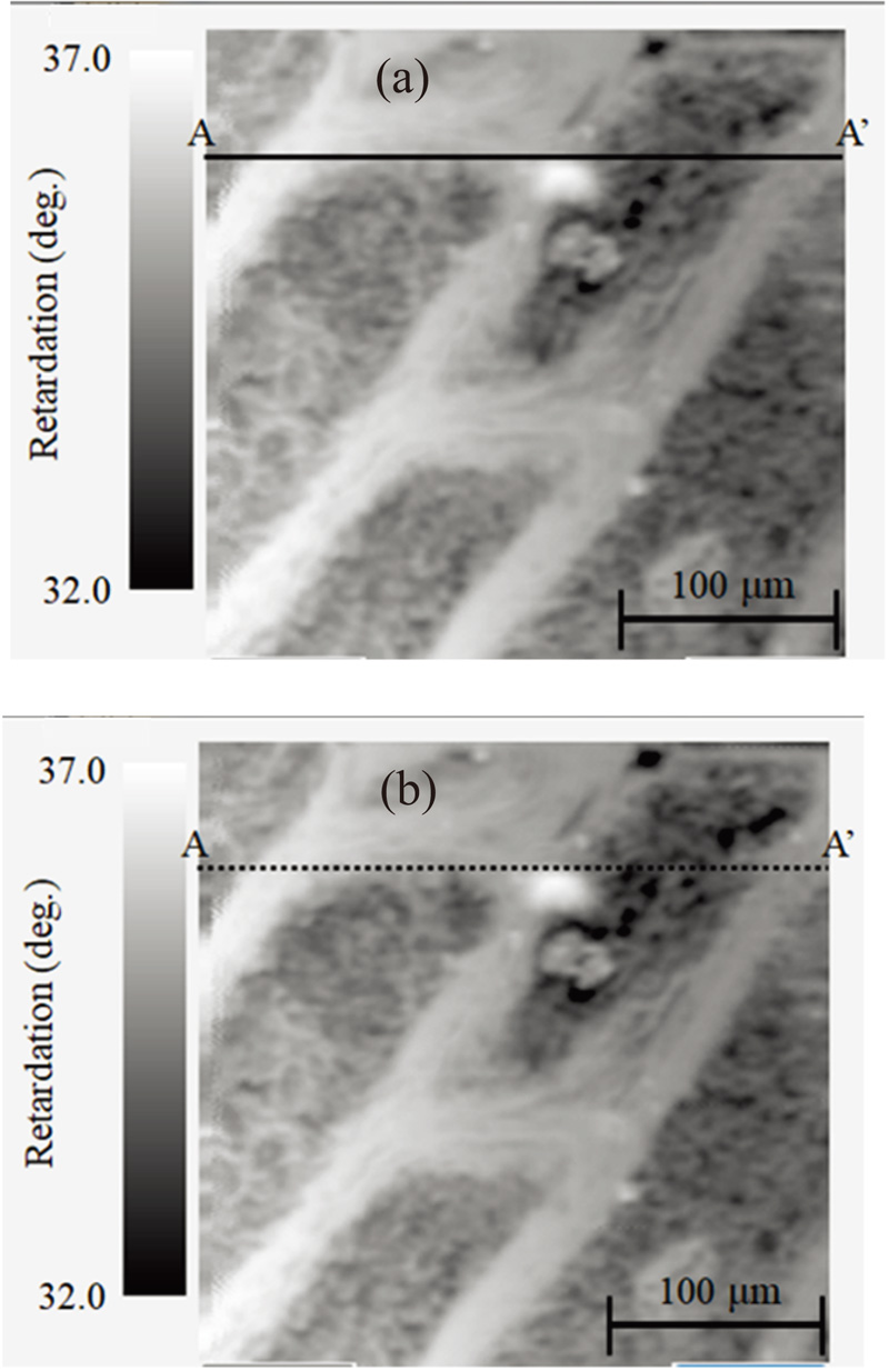
Obtained retardation images of onion
- [1] M. Kumagai, “Development of a 3D vision range sensor using equiphase light section method,” J. Robot. Mechatron., Vol.17, No.2, pp. 110-115, doi: 10.20965/jrm.2005.p0110, 2005.
- [2] A. Obara, X. Yang, and H. Oku, “Structured light field generated by two projectors for high-speed three dimensional measurement,” J. Robot. Mechatron., Vol.28, No.4, pp. 523-532, doi: 10.20965/jrm.2016.p0523, 2016.
- [3] H. Higuchi, H. Fujii, A. Taniguchi, M. Watanabe, A. Yamashita, and H. Asama, “3D measurement of large structure by multiple cameras and a ring laser,” J. Robot. Mechatron., Vol.31, No.2, pp. 251-262, doi: 10.20965/jrm.2019.p0251, 2019.
- [4] T. Tsuru, “Tilt-ellipsometry of object surface by specular reflection for three-dimensional shape measurement,” Optics Express, Vol.21, No.5, pp. 6625-6632, doi: 10.1364/OE.21.006625, 2013.
- [5] S. Ohkubo, “Observation of sample with the simplified mode birefringence optical microscope,” Proc. of Int. Symp. on Optomechatronics Technology (ISOT 2016), SS2-7, 2016.
- [6] E. Collett, “Field Guide to Polarization,” The Society of Photo-Optical Instrumentation Engineers, Society of Photo Optical, doi: 10.1117/3.626141, 2005.
- [7] D. H. Goldstein, “Polarized Light (Third Edition),” CRC Press, 2011.
- [8] J. Pawley, “Handbook of Biological Confocal Microscopy,” Springer, doi: 10.1007/978-0-387-45524-2, 1995.
- [9] R. A. Chipman, W. T. Lam, and G. Young, “Polarized Light and Optical Systems,” CRC Press, doi: 10.1201/9781351129121, 2018.
- [10] A. L. Gratiet, M. Dubreuil, S. Rivet, and Y. L. Grand, “Scanning Mueller polarimetric microscopy,” Opt. Lett., Vol.41, No.18, pp. 4336-4339, doi: 10.1364/OL.41.004336, 2016.
- [11] S. Y. Lu and R. A. Chipman, “Interpretation of Mueller matrix based on polar decomposition,” J. Opt. Soc. Am. A, Vol.13, No.5, pp. 1106-1113, doi: 10.1364/JOSAA.13.001106, 1996.
- [12] J. Wolfe and R. A. Chipman, “High speed imaging polarimeter,” Proc. of Optical Science and Technology, SPIE’s 48th Annual Meeting, Vol.5158, pp. 24-27, doi: 10.1117/12.504439, 2003.
This article is published under a Creative Commons Attribution-NoDerivatives 4.0 Internationa License.